Salus ERT50 User manual

Instruction Manual
Model No
ERT50
ERT50
Digital Room Thermostat
for Underoor
Heating Applications

ERT50 INSTRUCTION MANUAL
2
PRODUCT COMPLIANCE
This product complies with the essential
requirements of the following EC Directives:
•Electro-Magnetic Compatibility
directive 2004/108/EC
•Low Voltage Directive 2006/95/EEC
•EC Marking directive 93/68/EEC
SAFETY INFORMATION
These instructions are applicable to the Salus
Controls model stated on the front cover of this
manual only, and must not be used with any other
make or model.
These instructions are intended to apply in the
United Kingdom only, and should be followed along
with any other statutory obligations.
This accessory must be fitted by a Competent
person, and installation must comply with the
guidance provided in the current editions of
BS7671 (IEE Wiring Regulations) and Part ‘P’ of the
Building Regulations. Failure to comply with the
requirements of these publications could lead to
prosecution.
Always isolate the AC Mains supply before
opening or removing the unit from the wall or
wall box.
Please leave these instructions with the end user
where they should be kept in a safe place for future
reference.

ERT50 INSTRUCTION MANUAL 3
INTRODUCTION
A programmable thermostat is a device that combines
the functions of both a room thermostat and heating
controller into a single unit. The programmable
thermostat is used to switch the heating system in your
home on and off as needed. It works by controlling
the temperature according to a series of programmed
settings that take effect at different times of the day.
The ERT50 from Salus Controls is a stylish and accurate
digital room thermostat that is tted with a large easy
to read Liquid Crystal Display (LCD). The ERT50 benets
from simple one-touch operation, and this thermostat
has been specically designed to be used with underoor
heating systems. A back light and frost function adds to
the features of the ERT50.
Features
•Valve Protection Function (VPF)
•Night Setback (NSB) capability
•Solid State Relay output
•Large, easy to read dot matrix LCD with orange display
•Stylish casing
•User friendly
•Frost protection
•Reset button

INSTALLATION
Please read the important safety information at the start
of this manual before you begin to install the device.
The ideal position to locate the ERT50 digital room
thermostat is about 1.5m above oor level. It should
be mounted in a location where the thermostat is easily
accessible, reasonably lit and free from extremes of
temperature. The electrical connections to the ERT50 are
made to the internal terminal strip. Connection details
are shown below - no Earth connection is required for the
correct and safe operation of the thermostat as the device
is double insulated.
Terminal Connections
Terminal Description Terminal Block
N Mains Neutral
Switched Output
L Mains Live
Temperature setback
(110V AC input)
After installing the ERT50 in a suitable location, wiring
connections can be made as shown above. The following
criteria apply to the installation:
• The incoming AC mains supply should be 110V AC
and fused at 5 amps.
• Optimum cable size for installation is 1.5 mm2; wiring
colours should be in accordance with the current
requirements of the IEE Wiring Regulations.
• All wiring connections should be securely made,
and be rmly terminated within each of the terminal
screw clamps.
ERT50 INSTRUCTION MANUAL
4
110V
60Hz

ERT50 INSTRUCTION MANUAL 5
Do not restore the mains supply to the system until all
associated items are fully installed.
NOTE: All electrical installation work should be carried out by a
suitably qualied Electrician or other competent person. If you
are not sure how to install this programmable thermostat consult
either with a qualied electrician, heating engineer or your
boiler / heating system supplier for advice on how to continue.
Do not remove or refit the ERT50 wiring without the
mains supply to the system being isolated.
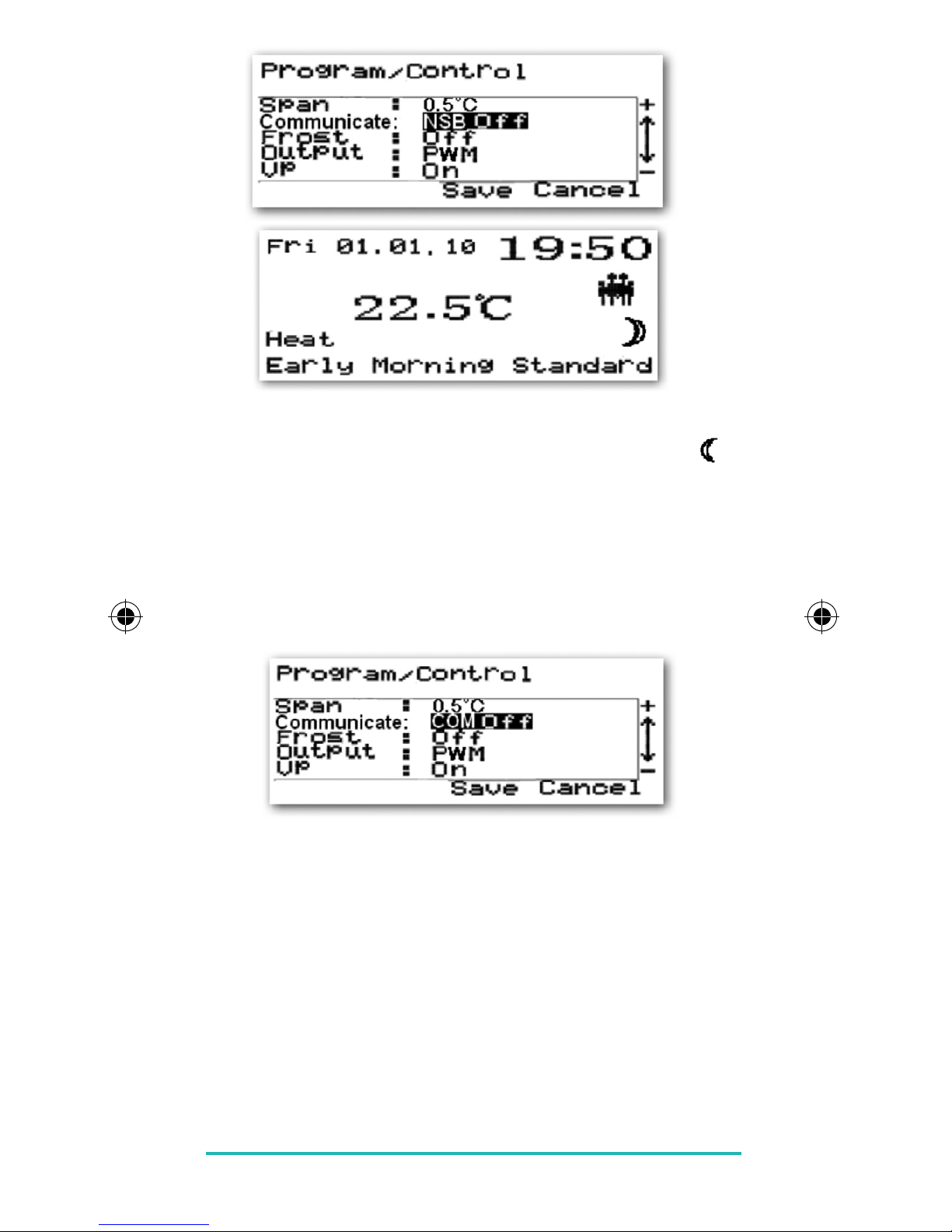
SETTING MODES
When the ERT50 is rst powered up, the Start Up Display
will be shown.
Basic Settings
Many of the ERT50 conguration and operating settings
can be changed here. Press any key to turn on the
backlight, press CANCEL key, press and hold the SELECT
and CANCEL keys together to enter program setting press
+ or - key to “Basic Setting”, and press SELECT.
To change any of the basic settings, press the SELECT this
will access the Program/Basic settings menu.
Use the PLUS (+) or MINUS (-) keys to choose the item you
want to change and press the SELECT key to change to the
setting menu for that item. Pressing the CANCEL key will
exit from this menu and return you to the previous menu.

ERT50 INSTRUCTION MANUAL
6
DATE AND TIME:
Press the PLUS or MINUS key to change the day setting,
then SELECT to save your choice. Do exactly the same for
the month and year. You can then choose whether to use
a 12 or 24 hour time display (the default is 24 hour).
The time is set in the same way as the date – use the
PLUS or MINUS keys to change the setting, and save
by pressing SELECT.
The last menu item is Daylight Saving – by default this is
turned on. Change the setting using the PLUS or MINUS keys,
then press the SELECT key to save the settings and return to
the Program/Basic settings menu.

LANGUAGE:
The ERT50 is programmed to operate in eight different
languages (the default is English). If you wish to change
the language used, select Language from the Program/
Basic Settings screen.
Select your choice of language with the PLUS or MINUS
keys, then press SELECT to save your choice and return to
the Program/Basic Settings screen.
Pressing CANCEL will return to the previous screen
without saving any changes. You can also access the
Language menu by pressing the MENU and SELECT keys
and the RESET button together.
MAINTENANCE:
The Maintenance menu allows you to view operating
times for the heating system. The ERT50 will record
operating time up to a maximum of 99,999 hours.
ERT50 INSTRUCTION MANUAL 7

ERT50 INSTRUCTION MANUAL
8
Select the Read Operating Time entry to see a summary of
the system operating times.
This screen will show the date the operating times were last
reset, total operating time and total actuator open time.
The timers can be reset by selecting the Reset Operating
Time item.
Select Yes and then press the SELECT key to reset the timers
to 0.
Press the CANCEL key twice to return to the Program menu.

CONTROL SETTINGS
The Control menu allows changes to the Temperature
Span, Communications, Frost Protection, Output, Valve
Protection and Temperature Offset settings.
To access this menu, select the Control item from the
Program menu.
Temperature Span:
The rst setting that can be changed is Temperature Span.
The default setting is 0.5 °C, but this can be changed to
1.0 °C. Press the SELECT key to save your changes.
COMMUNICATIONS:
The Communicate menu item has several setting options,
some of which are only relevant when there is more than
one thermostat in the installation and they are congured
in a Master/Slave relationship.
The rst option allows you to turn Night Setback on or
off. The Setback feature will only operate if a connection
is made to the Setback terminal .
ERT50 INSTRUCTION MANUAL 9

ERT50 INSTRUCTION MANUAL
10
The terminal is sampled every second, and if the terminal
state is HIGH (above 175V AC) the Crescent indicator
will be shown on the display and the Setback temperature
will be applied.
You can only change the other Communications options
if NSB is set to OFF – if NSB is turned ON the ERT50 will be
set as the Master unit and will only send a signal to any
Slave units, not receive a signal from them.
With NSB set to Off, you can then change the other
communications options by using the PLUS and MINUS
keys. The available options are COM Off, COM 4 ºC and
COM 2 ºC. If COM Off is selected, no setback signal will
be sent to the Slave thermostat. With COM 4 ºC or COM
2 ºC selected, the slave thermostat temperature will
be reduced or increased by 4 ºC or 2 ºC, depending on
whether the system is in Heating or Cooling mode.
After choosing your option, press the SELECT key to save
your selection and exit from the menu.

FROST PROTECTION:
Selecting the Frost item in the menu allows you to turn
the frost protection mode of the ERT50 on or off (the
default setting is On).
The Frost Protection mode temperature is preset at 5 ºC;
this temperature is factory set and cannot be adjusted.
The Frost Protection mode indicator will ash every 2
seconds to indicate Frost Protection mode is active.
ERT50 INSTRUCTION MANUAL 11

ERT50 INSTRUCTION MANUAL
12
OUTPUT:
By selecting the Output menu item, you can change the
control method used by the programmable thermostat
- either Pulse Width Modulation (PWM) or On/Off. The
default setting is PWM.
PWM only functions when the controller is operating in
Heat mode.
VALVE PROTECTION FUNCTION:
The Valve Protection (VP) function is provided as a way
to avoid the control valve from sticking or seizing when
not being used for long periods (e.g. during the summer).
This function is enabled by turning the Valve Protection
feature on or off using the PLUS or MINUS keys (default
setting is On).
When enabled, the VP function will turn on the
thermostat output to operate the control valve for a
period of 5 minutes every week - the Valve Protection
function will still operate even if the room temperature
is higher than 35 °C.

TEMPERATURE OFFSET:
The Temperature Offset menu item is an adjustable
setting that allows calibration of the controller to match
the ambient temperature. The Offset can be adjusted
between –3.5 °C and +3.5 °C in 0.5 °C steps.
Use the PLUS and MINUS keys to adjust the Offset setting,
and save your changes by pressing the SELECT key. After
saving the setting, the ERT50 will revert back to the
Program menu.
Pressing CANCEL will return you to the Program menu
without saving your changes.
HEAT/COOL:
The Heat/Cool menu allows you to select the ERT50’s
operating mode (heating or cooling).
Select your choice of mode using the PLUS and MINUS
keys, and save using the SELECT key.
ERT50 INSTRUCTION MANUAL 13

ERT50 INSTRUCTION MANUAL
14
Changing the operating mode will also change the
Comfort and Reduced temperature settings. The ERT50
screen will look like this in Heating mode:
…and like this when in Cooling mode.
AFTER INSTALLATION:
After completing installation and powering up the
ERT50 for the rst time the thermostat will behave in the
following way: All the indicators on the display and the
backlight will be turned on for two seconds and display
the installed rmware version. After two seconds, the
ERT50 will then operate in Normal mode (controller
output OFF), and display the Change Display menu
screen:
Select an option by using the PLUS or MINUS keys and
pressing the SELECT key. If the Reset Button is pressed,
the ERT50 will behave in the same way as described
above, except that any previously saved user settings will
be deleted and overwritten with the default settings.

Function Factory Default Value
Operation Mode Normal
Room Temperature 24 ºC, updated within 5 seconds
Display Mode Full Screen
Date Format DD/MM/YY
Clock 00:00 (24 hour)
Day Fri 01/01/10
Key Lock Off
Holiday On/Off Off
Program On/Off On
Language English
Timers 0 hours
Heat/Cool Heat
Span 0.5 °C
NSB (setback) Off
Frost Protection Off
Output Mode PWM
Valve Protection On
Offset 0 °C
Output Off
LCD Backlight Off
Daylight Saving On
N.B: Please be aware that after a Reset, the ERT50 output
relay may turn ON if the room temperature is lower than
the Set Point temperature.
ERT50 INSTRUCTION MANUAL 15

ERT50 INSTRUCTION MANUAL
16
USER INTERFACE AND CONTROLS:
The status and operation of the ERT50 can be clearly seen
on the large orange backlit Liquid Crystal Display (LCD) -
this display allows the user to see at a glance the current
status of the heating system.
There are few user controls for the ERT50, making the
controller very easy to operate.
The MENU, PLUS (+), MINUS (-) and RESET keys are easily
accessible on the front panel of the controller, just below
the display. The SELECT and CANCEL keys are accessible
after opening the hinged cover on the front of the
controller.
These controls are shown below, along with a description
of each of their functions.

USER CONTROL FUNCTION SUMMARY:
Key/Operation Symbol Functions
MENU key Activates the menu function
of the ERT50
MINUS (-) key Decreases the selected setting
PLUS (+) key Increases the selected setting
RESET button Resets the controller to default
(original factory) settings
SELECT key Selects or saves the currently
highlighted menu or setting
CANCEL key Cancels the current selection
or exits the active menu
OPERATION
As previously described, the ERT50 is congured and
adjusted by the use of an intuitive user interface with a
minimal number of user controls, and the backlit LCD
gives a highly visible, easily readable indication of the
thermostat status.
ERT50 INSTRUCTION MANUAL 17

ERT50 INSTRUCTION MANUAL
18
LCD INDICATOR FUNCTION SUMMARY:
Indicator Symbol Function
FROST (left Indicates frost protection
hand side mode is active.
– ashing)
CRESCENT Indicates setback temperature
mode is active.
TEMPERATURE Indicates either current room
temperature or set
point temperature.
COOLING Indicates cooling mode is active.
HEATING Indicates heat control
mode is active.
KEY LOCK Indicates key lock is turned on.
MANUAL Indicates the controller is
operating in manual mode.
HOLIDAY Indicates holiday mode is active.
FAMILY Preset (predened) prole for
family environments.
SINGLE Preset (predened) prole for
single user environments.
OFFICE Preset (predened) prole for
ofce environments.
NAME 1 User denable and
re-nameable prole.
NAME 2 User denable and
re-nameable prole

PROFILES:
The ERT50 has a number of preset proles that simplify
installation and setup. The profiles contain default
settings that should meet the majority of needs in a
range of environments, meaning that the controller can
work ‘out of the box’ with no reprogramming. The ve
preinstalled proles are:
FAMILY
SINGLE
OFFICE
NAME 1
NAME 2
Each prole has settings for 7 weekdays, 6 different times
of day and 3 different temperature zones:
Time of Day Start End
Early Morning 06:00 08:00
Morning 08:00 12:00
Noon 12:00 14:00
Afternoon 14:00 18:00
Evening 18:00 23:00
Night 23:00 06:00
Temperature Zone Setting
(heating mode)
Standard 20.0 °C
Comfort 24.0 °C
Reduced 16.0 °C
Programming the ERT50 is very easy, and only needs you
to select a combination of times of day and temperature
zone, as in these examples:
ERT50 INSTRUCTION MANUAL 19

ERT50 INSTRUCTION MANUAL
20
Example 1 – Prole=Family, Days=Mon-Fri
Early Morning 06:00 08:00 Comfort
Morning 08:00 12:00 Standard
Noon 12:00 14:00 Comfort
Afternoon 14:00 18:00 Standard
Evening 18:00 23:00 Comfort
Night 23:00 06:00 Reduced
Example 2 – Prole=Single, Days=Mon-Fri
Early Morning 06:30 07:30 Comfort
Morning 07:30 12:00 Standard
Noon 12:00 15:00 Comfort
Afternoon 15:00 16:00 Standard
Evening 16:00 00:00 Comfort
Night 00:00 06:30 Reduced
EVERYDAY FUNCTIONS (EDF)
The ERT50 gives the user the option of three different
idle screen display modes, depending on the user’s
preference: Full screen, Selected screen or Basic Screen.
In all three idle screen modes, the displayed temperature
is the current room temperature.
Full Screen:
In full screen mode the weekday, date, time, temperature,
heat or cool, time of day, temperature zone and prole
are displayed.
Other manuals for ERT50
3
Table of contents
Other Salus Thermostat manuals

Salus
Salus iT500BM User guide

Salus
Salus RT310i User manual

Salus
Salus RT510BC+ User manual

Salus
Salus Optima S User manual

Salus
Salus AHTR5024 User guide

Salus
Salus 091FLRF User manual

Salus
Salus iT600 Series Operation and installation manual

Salus
Salus RTS00RF User manual

Salus
Salus FT100 User manual

Salus
Salus RT100 User manual

Salus
Salus ERT20RF User manual

Salus
Salus CE-HTR230 User guide

Salus
Salus ERT 52 User manual

Salus
Salus BTR230 User manual

Salus
Salus iT500 User guide

Salus
Salus RT300RF User manual

Salus
Salus RT510LG5V User manual

Salus
Salus Quantum WQ610 User manual

Salus
Salus VS10WRF User manual

Salus
Salus iT500 User manual