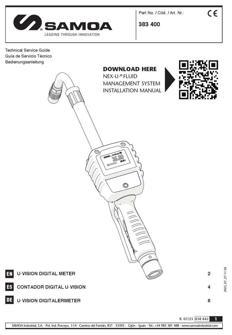
Samoa U-VISION 383 400 Operating manual

1
R. 07/17 838 842
SAMOA Industrial, S.A. · Pol. Ind. Porceyo, I-14 · Camino del Fontán, 831 · 33392 - Gijón - Spain · Tel.: +34 985 381 488 · www.samoaindustrial.com
2017_07_19-12:00
Part No. / Cód.:
383 400
U·VISION CONTROL METER 2
PISTOLA CONTADORA U·VISION 7
EN
ES
Parts and technical service guide
Guía de servicio técnico y recambio

2838 842 R. 07/17
SAMOA Industrial, S.A. · Pol. Ind. Porceyo, I-14 · Camino del Fontán, 831 · 33392 - Gijón - Spain · Tel.: +34 985 381 488 · www.samoaindustrial.com
EN
2017_07_19-12:00
- This unit is only compatible with the Samoa control gun
provided with outlet flange. In case of doubt or further
detailed information, pleas contact your sales representative.
- This unit can not operate by itself and is intented to
operate with a U·meter+, U·valve or U·count unit.
- In order to operate properly a previous configuration is
needed. Consult the configuration chapter.
- Only use the unit for the purposes for which it is intended.
- This unit has not been approved for use in commercial
transactions.
WARNING: This unit is intented for professional use.
Reada all the instructions in this manual prior to use.
Follow the next procedure in order to install the U·Vision unit on a control gun:
1. Mount the extension outlet (1) if it is not already attached.
2. In the case that the control gun has the plastic cover (2) mounted, remove it by means of a screwdriver or similar
tool. The cover is pressure mounted, it should be easily removed.
If the flange cover is mounted, remove it as well.
3. Slide the U·Vision unit (3) through the extension outlet (1) untill it remains properly fitted onto the flange.
4. By means of the nut, screw and washer kit (4) provided, attach the unit to the flange as indicated in the figure.
INTRODUCTION
!- Do not alter or modify the unit.
- It is mandatory to respect the polarity of batteries and follow
its order of placement as indicated in the batteries cover.
- If a leakage is detected in the batteries protect your eyes
and skin. Cover the batteries housing with a cloth before
opening it to avoid that acid get sprayed onto your skin
or eyes. If acid should spray into your eyes, rinse
immediately with clear water for several minutes.
Consult a doctor immediately afterwards
- Do not mix different battery brands.
- Do not mix new batteries with old ones.
ASSEMBLY
123
4

3
R. 07/17 838 842
SAMOA Industrial, S.A. · Pol. Ind. Porceyo, I-14 · Camino del Fontán, 831 · 33392 - Gijón - Spain · Tel.: +34 985 381 488 · www.samoaindustrial.com
EN
2017_07_19-12:00
BATTERIES INSTALLATION AND REPLACEMENT
NOTE: The U·Vision unit is supplied without the batteries
installed, follow the next steps for proper installation.
1. Loosen the screws (1) with a T15 torx tool and remove
the battery cover (2).
2. Install the supplied batteries (3) checking the polarity as
indicated in the cover (4).
3. Put back the cover (2) and tighten the screws (1).
CAUTION: To ensure battery compartment
watertightness, make sure that the battery cover is
properly placed and the screws tightened.
!
CONFIGURATION
This unit can be paired with a U·meter+, U·valve or U·count unit.
Pressing the power button shows the start screen (fig. 1) during a short time. In the bottom left screen it is shown the
actual U·Vision firmware.
Then the unit will try connection showing the connecting screen (fig. 2). This screen will disappear after a brief moment
if the unit has already been configured, but if it has not been paired then the message will stay on screen waiting for
configuration.
PAIRING THE U·VISION WITH A FLUID MANAGEMENT UNIT
Fig. 1 Fig. 2
Fig. 5
Fig. 6
Fig. 7
1
3
2
4
2

4838 842 R. 07/17
SAMOA Industrial, S.A. · Pol. Ind. Porceyo, I-14 · Camino del Fontán, 831 · 33392 - Gijón - Spain · Tel.: +34 985 381 488 · www.samoaindustrial.com
EN
2017_07_19-12:00
CONFIGURATION
1. Starting from the connecting screen (figure 2) press and
hold the power button until “setup” is shown on the
screen (figure 3). Release the button.
2. Next the configuration screen is shown automatically
(figure 4). The unit remains waiting for the hose reel
number that you want to associate.
3. The hose reel number starts to increase automatically.
When the desired hose reel number is shown, press and
release the power button to set it. In case that the desired
hose reel number is missed, press and hold the power
button until the counter restarts.
4. Once that the hose reel number is set, the screen shows
that the configuration is performed and the unit restarts
(figure 5). After restarting the screen shows that the
U·Vision is configured and ready to operate (figure 6).
USING YOUR U·VISION
If the unit has been properly configured a short press on
the power button shows on the screen the “ready for use”
mode (figure 7).
When the screen is displayed, the backlight is activated
during 10 seconds and then turned off. After 30 seconds
since the display is activated and if there is no transaction
in progress, the unit will turn off to save energy. If the unit
is off press the power button to activate it.
If the screen is on and you want to activate the backlight press
briefly the power button in order to activate it for 10 seconds.
Fig. 3 Fig. 4
Fig. 5 Fig. 6
Fig. 7
NOTE: make sure that the U·meter+, U·valve or U·count unit is powered on before pairing the U·Vision.
Follow the below instructions to pair your U·Vision:
In the “ready for use mode” (figure 7) are displayed the
product (1) associated to the hose reel, the battery charge
indicator (2), the wireless strength (3) and the hose reel
number (4) paired.

5
R. 07/17 838 842
SAMOA Industrial, S.A. · Pol. Ind. Porceyo, I-14 · Camino del Fontán, 831 · 33392 - Gijón - Spain · Tel.: +34 985 381 488 · www.samoaindustrial.com
EN
2017_07_19-12:00
USING YOUR U·VISION
When a transaction is launched in the management system
then the screen shows the transaction mode (figure 8) in
which it can be seen the preselected amount (5).
Once that the transaction is finished the screen shows for
a few seconds the amount dispensed (figure 10).
When the trigger of the control valve gun is pulled the fluid
amount being dispensed (6) is displayed. The solenoid valve
open indicator (7) appears on the screen as long as the
U·meter+, U·valve or U·count solenoid valve is open.
After that, depending on the monitoring system setup, the
topping screen (figure 11) is shown for a certain amount of
time previously preconfigured in the system. During this
period of time it is possible to make the topping from a
keypad. Once that the topping time limit is reached the
screen returns to the “ready for use mode”.
Fig. 8
Fig. 9
Fig. 10
Fig. 11
2 43
5
1
6
7
BYPASS MODE
The by-pass mode can be activated from a keypad by
means of a key. When this mode is on it is shown on the
screen the information indicated in figure 12.
The open solenoid valve indicator (7) is shown on the
screen and the fluid can be dispensed. The quantity
displayed on the screen (8) indicates the total quantity of
fluid dispensed by the unit since it has been switched to
bypass mode (“total” meter).
Fig. 12
7
8

6838 842 R. 07/17
SAMOA Industrial, S.A. · Pol. Ind. Porceyo, I-14 · Camino del Fontán, 831 · 33392 - Gijón - Spain · Tel.: +34 985 381 488 · www.samoaindustrial.com
EN
2017_07_19-12:00
BYPASS MODE
TECHNICAL SPECIFICATIONS
Unit compatibility SAMOA oil control gun
Batteries 4 x AA / LR6
Connectivity Bluetooth LE
Temperature operation range -10 ºC a 60 ºC
Weight 420 g (0.92 lb)
Display Dot matrix 128x64 with
backlight
This device complies with Part 15 of the FCC Rules.
Operation is subject to the following two conditions: (1)
this device may not cause harmful interference, and (2) this
device must accept any interference received, including
interference That may cause undesired operation.
TROUBLESHOOTING
Symptom Possible cause Solution
Lack of connection Unit not configured Consult pairing instructions
The screen does not turn on Wrong batteries assembly Check batteries polarity
Batteries run out of energy Replace batteries
The unit is configured but it does
not work Wrong pairing Check that the unit is paired with the
correct hose reel
DISPOSAL INFORMATION
The symbol above means that according to local laws and regulations your product and/or its
battery must be disposed of separately from household waste. When this product reaches its end of
life, take it to a collection point designated by local authorities. The separate collection and recycling
of your product and/or its battery at the time of disposal will help conserve natural resources and
ensure that it is recycled in a manner that protects human health and the environment.
Under these mode, a “trip” meter is available in order to
simplify the execution of individual dispenses. To do this,
just press and hold the “power” button until the displayed
quantity changes to zero (9). From now on, the dispensed
volume will increase from zero (“trip” meter). The “total”
meter will now be displayed on the bottom right corner of
the screen (10), next to the units.
CAUTION:
In by-pass mode the amount of fluid dispensed is not
registered in the monitoring system. Fig. 13
9
10

7
R. 07/17 838 842
SAMOA Industrial, S.A. · Pol. Ind. Porceyo, I-14 · Camino del Fontán, 831 · 33392 - Gijón - Spain · Tel.: +34 985 381 488 · www.samoaindustrial.com
EN
2017_07_19-12:00
ES
- Este equipo es sólo compatible con la pistola Samoa
dotada de brida en su salida. En caso de duda de
compatibilidad consulte a su distribuidor.
- Este equipo precisa para su funcionamiento de una
unidad U·meter, U·meter+ U·valve o U·count.
- Para su correcto funcionamiento necesita de una
configuración previa. Consulte el apartado correspondiente.
- Use el equipo sólo para los fines a los que está destinado.
ADVERTENCIA: Este equipo está destinado a uso
profesional. Lea todas las instrucciones de este
manual antes de su uso.
Para instalar el módulo U-Vision en una pistola siga el siguiente procedimiento:
1. Instale la extensión (1) en la pistola si no está ya montada.
2. En caso de que la pistola tenga montada la tapa embellecedora (2) retírela con ayuda de un destornillador o
herramienta similar. La tapa está montada a presión, debería salir con un ligero esfuerzo.
Si el protector de brida está instalado, retírelo.
3. Deslice el módulo U·vision (3) por la extensión (1) hasta que permanece correctamente encajado en su alojamiento
en la brida.
4. Con el kit (4) de de tuerca, tornillo y arandela suministrado fije el módulo a la brida de pistola como se indica en la imagen.
INTRODUCCIÓN
!- No altere o modifique el equipo.
- Es obligatorio respetar la polaridad de las baterías y
seguir el orden de colocación indicado en la tapa.
- Si se produce una fuga en las pilas, protéjase los ojos.
Abra la caja de las pilas después de haberla cubierto con
un paño para evitar cualquier salpicadura. En caso de
contacto con el líquido liberado por la pila, enjuague
inmediatamente con agua limpia y consulte a un médico
urgentemente.
- No mezcle pilas de marcas diferentes
- No mezcle pilas nuevas con pilas utilizadas
MONTAJE
123
4

8838 842 R. 07/17
SAMOA Industrial, S.A. · Pol. Ind. Porceyo, I-14 · Camino del Fontán, 831 · 33392 - Gijón - Spain · Tel.: +34 985 381 488 · www.samoaindustrial.com
2017_07_19-12:00
ES
MONTAJE Y SUSTITUCIÓN DE LAS BATERÍAS
ATENCIÓN: El módulo U-Vision se suministra sin las pilas
montadas, siga el siguiente procedimiento para instalarlas:
1. Afloje los tornillos (1) con la llave torx T15 y retire la
tapa (2) del compartimento de baterías.
2. Instale las baterías suministradas (3) respetando la
polaridad (4) indicada en la tapa.
3. Vuelva a poner la tapa (2) y apriete los tornillos (1).
ADVERTENCIA: Para garantizar la estanqueidad
del compartimento de pilas, asegúrese de que la
tapa está correctamente colocada y los tornillos
apretados.
!
CONFIGURACIÓN
La unidad U·vision puede emparejarse con una unidad U·meter+, U·valve o U·count.
La pulsación del botón de encendido muestra la pantalla de inicio (fig 1) durante un instante. En la parte inferior
izquierda de la pantalla se muestra la versión de software de la pistola.
A continuación la pistola intentará conectarse mostrando la pantalla de intento de conexión (fig. 2). Si la pistola ya ha
sido configurada esta pantalla desaparecerá tras un breve instante, pero si no ha sido emparejada permanecerá fija a la
espera de su configuración.
EMPAREJAMIENTO DEL MÓDULO U-VISION CON UNA UNIDAD DE CONTROL DE FLUIDO
Fig. 1 Fig. 2
Fig. 5
Fig. 6
Fig. 7
1
3
2
4
2
NOTA: Asegúrese de que la unidad U·meter+, U·valve o U·count está encendida antes de emparejar la pistola.
Para emparejar la pistola siga el siguiente procedimiento:

9
R. 07/17 838 842
SAMOA Industrial, S.A. · Pol. Ind. Porceyo, I-14 · Camino del Fontán, 831 · 33392 - Gijón - Spain · Tel.: +34 985 381 488 · www.samoaindustrial.com
EN
2017_07_19-12:00
ES
CONFIGURACIÓN
1. Desde la pantalla de conexión (figura 2) presione el
botón de encendido hasta que la pistola muestre
“setup” (figura 3) en pantalla.
2. A continuación se muestra automáticamente la pantalla
de configuración (figura 4). La pistola queda a la espera
de introducir el número de enrollador que desea asociar.
3. El número de enrollador comienza a incrementarse
automáticamente. Cuando el número de enrollador
deseado se muestre, realice una pulsación corta del
botón de encendido para fijarlo. En caso de que se haya
saltado el número de enrollador deseado mantenga
presionado el botón de encendido hasta que el
contador se reinicie.
4. Una vez fijado el número de enrollador se muestra por
pantalla la aceptación de la configuración y la pistola se
reinicia (figura 5). Tras el reinicio la pistola muestra por
pantalla que está configurada y lista para operar (figura 6).
MODO DE OPERACIÓN
Si la pistola está correctamente emparejada, la pulsación
del botón de encendido muestra por pantalla el modo de
espera (figura 7).
Al encender la pantalla la retroiluminación se activa
durante 10 segundos. Transcurridos 30 segundos desde la
activación de pantalla y si no hay ninguna transacción en
curso la pantalla se apagará para ahorrar energía. Si la
pistola se encuentra en modo apagado pulse el botón de
encendido para activarla.
Si la pantalla está encendida y desea activar la
retroiluminación pulse el botón de encendido y se activará
durante 10 segundos.
Fig. 3 Fig. 4
Fig. 5
Fig. 6
Fig. 7
En el modo de espera (fig. 7) se visualiza el producto (1)
asociado al enrollador, el nivel de carga de las pilas (2), la
cobertura inalámbrica (3) y el número de enrollador (4)
emparejado.

10 838 842 R. 07/17
SAMOA Industrial, S.A. · Pol. Ind. Porceyo, I-14 · Camino del Fontán, 831 · 33392 - Gijón - Spain · Tel.: +34 985 381 488 · www.samoaindustrial.com
2017_07_19-12:00
ES
MODO DE OPERACIÓN
Cuando se lanza una transacción en el sistema la pantalla
muestra el modo transacción (fig. 8) en el que se puede
ver la cantidad preseleccionada (5).
Una vez terminada la transacción se muestra durante unos
segundos la cantidad dispensada (figura 10).
Al accionar el gatillo de pistola se muestra la cantidad
suministrada (6) en pantalla. El indicador de electroválvula
abierta (7) aparece en la parte superior mientras la electroválvula
del U·meter+, U·valve o U·count permanezca abierta.
A continuación, dependiendo de la configuración del
sistema, se muestra la pantalla de topping (figura 11)
durante un cierto tiempo configurado en el sistema.
Durante este periodo es posible realizar topping desde un
teclado. Transcurrido el tiempo de visualización del modo
topping la pantalla vuelve al modo de espera.
Fig. 8
Fig. 9
Fig. 10
Fig. 11
2 43
5
1
6
7
Fig. 12
7
8
MODO DE OPERACIÓN EN BYPASS
El modo by-pass puede ser activado desde la llave de un
teclado. Cuando este modo está activo en la pantalla de la
pistola se visualiza la imagen mostrada en la figura 12:
El símbolo de electroválvula abierta (7) se muestra en
pantalla y puede comenzar a dispensar fluido accionando
el gatillo de pistola. La cantidad mostrada en pantalla (8)
es la cantidad total dispensada por la unidad desde su
puesta en modo bypass (contador total).

11
R. 07/17 838 842
SAMOA Industrial, S.A. · Pol. Ind. Porceyo, I-14 · Camino del Fontán, 831 · 33392 - Gijón - Spain · Tel.: +34 985 381 488 · www.samoaindustrial.com
EN
2017_07_19-12:00
ES
MODO DE OPERACIÓN EN BYPASS
ESPECIFICACIONES
Compatibilidad Pistola de aceite SAMOA
Alimentación 4 x AA
Banda de funcionamiento 2.4 GHZ ISM
Temperatura de operación -10 ºC a 60 ºC
Peso 420 g (0.92 lb)
Pantalla Dot matrix 128x64
retroiluminada
Este aparato cumple con la parte 15 de las Reglas de la
FCC. La operación está sujeta a las siguientes dos
condiciones. (1) Este aparato no podrá causar interferencia
dañina, y (2) este aparato debe aceptar cualquier
interferencia recibida, incluyendo interferencia que pueda
causar un funcionamiento indeseado. Si el aparato no es
instalado y utilizado de acuerdo con las instrucciones,
puede causar interferencia dañina para las radio
comunicaciones e invalidar la autoridad que tiene el
usuario para la garantía del equipo.
DIAGNÓSTICO Y SOLUCIÓN DE PROBLEMAS
Síntoma Posible causa Solución
Sin conexión Pistola no configurada Realice procedimiento de emparejamiento
La pantalla no enciende Montaje incorrecto de polaridad de pilas Verificar montaje de pilas
Pilas agotadas Sustituir pilas
La pistola está configurada pero
no cuenta Emparejamiento erróneo Verifique que la pistola está asociada al
enrollador correcto
INFORMACIÓN SOBRE DESECHO DE RESIDUOS
El símbolo anterior indica que, de acuerdo con las normativas locales, su producto y/o su batería
deberán desecharse de manera independiente de los residuos domésticos. Cuando este
producto alcance el final de su vida útil, deberá llevarlo a un punto de recogida designado por
las autoridades locales. La recogida separada y el reciclaje del producto o su batería en el
momento de su desecho ayudarán a proteger los recursos naturales y a garantizar su reciclaje
de forma que proteja la salud de las personas y el medio ambiente
Fig. 13
9
10
En dicho modo, es posible disponer de un contador parcial
(figura 13), para facilitar la ejecución de transacciones
individuales. Para ello, mantenga pulsado el botón de
encendido hasta que la cantidad mostrada en pantalla
cambie a cero (9). El volumen dispensado a partir de dicho
momento se irá incrementado desde cero (contador
parcial). El contador total pasará a mostrarse en la esquina
inferior derecha (10), junto con la unidad de medida.
ATENCIÓN:
En modo bypass el fluido dispensado no es registrado por
el sistema.

12 838 842 R. 07/17
SAMOA Industrial, S.A. · Pol. Ind. Porceyo, I-14 · Camino del Fontán, 831 · 33392 - Gijón - Spain · Tel.: +34 985 381 488 · www.samoaindustrial.com
2017_07_19-12:00
For SAMOA INDUSTRIAL, S.A.
Por SAMOA INDUSTRIAL, S.A.
Pour SAMOA INDUSTRIAL, S.A.
Für SAMOA INDUSTRIAL, S.A.
Pedro E. Prallong Álvarez
Production Director
Director de Producción
Directeur de Production
SAMOA INDUSTRIAL, S.A., Pol. Ind. Porceyo, I-14 ·
Camino del Fontán, 831 · 33392 - Gijón - Spain, declares
that the product(s): 383 400
conform(s) with the EU Directive(s): 2004/108/EC
EN
SAMOA INDUSTRIAL, S.A., Pol. Ind. Porceyo, I-14 ·
Camino del Fontán, 831 · 33392 - Gijón - España,
declara que el(los) producto(s): 383 400
cumple(n) con la(s) Directiva(s) de la Unión Europea:
2004/108/CE
ES
SAMOA INDUSTRIAL, S.A., Pol. Ind. Porceyo, I-14 ·
Camino del Fontán, 831 · 33392 - Gijón - Espagne,
déclare que le(s) produit(s): 383 400
est(sont) conforme(s) au(x) Directive(s) de l’Union
Européenne: 2004/108/CE
FR
SAMOA INDUSTRIAL, S.A., Pol. Ind. Porceyo, I-14 ·
Camino del Fontán, 831 · 33392 - Gijón- Spanien,
bestätigt hiermit, dass das (die) Produkt (e): 383 400
der (den) EG-Richtlinie(n): 2004/108/EG entspricht
(entsprechen).
DE
EC CONFORMITY DECLARATION / DECLARATION CE DE CONFORMIDAD /
DÉCLARATION CE DE CONFORMITÉ / EG-KONFORMITÄTSERKLÄRUNG
Other manuals for U-VISION 383 400
1
Table of contents
Languages:
Other Samoa Measuring Instrument manuals
Samoa
Samoa U.VALVE Operating manual

Samoa
Samoa 680300 Operating manual

Samoa
Samoa 366760 Operating manual

Samoa
Samoa 366010 User manual

Samoa
Samoa 365601 Operating manual

Samoa
Samoa U-METER User manual

Samoa
Samoa 411100 User manual
Samoa
Samoa NS-RGRCESS4 How to use

Samoa
Samoa 383 700 How to use

Samoa
Samoa Oval Gear Meter User manual