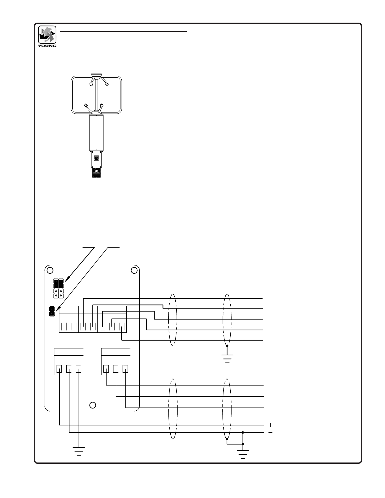
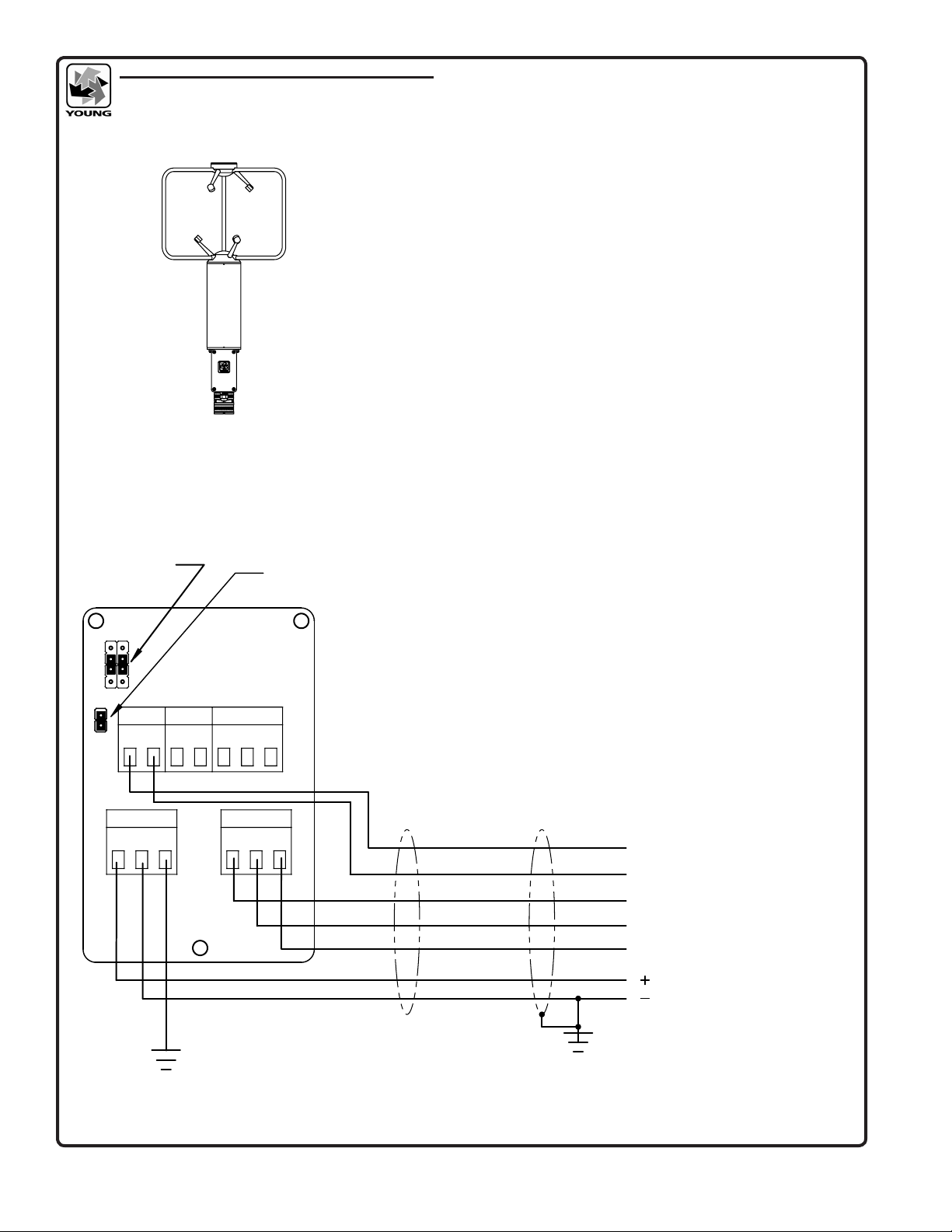
Young 81000V User manual

METEOROLOGICAL INSTRUMENTS
INSTRUCTIONS
R.M. YOUNG COMPANY 2801 AERO PARK DRIVE, TRAVERSE CITY, MICHIGAN 49686, USA
TEL: (231) 946-3980 FAX: (231) 946-4772 WEB: www.youngusa.com PN: 81000V-90
REV: L120820
ULTRASONIC ANEMOMETER
MODEL 81000V

Page 1 81000V-90(L)
MODEL 81000V
ULTRASONIC ANEMOMETER
2.0 INTRODUCTION
The Young Model 81000V measures three dimensional wind velocity
and speed of sound based on the transit time of ultrasonic acoustic
signals. Sonic temperature is derived from speed of sound which
is corrected for crosswind effects. Four voltage input channels
measure DC signals from external sensors concurrent with wind
measurements.
Measurement data are available as serial output using RS-232 or
RS-485 connections. A variety of serial output formats are available
including a custom format which is easily set by the user.
Operating parameters may be edited via simplied menus using
an ordinary serial communication program like HyperTerm. All
parameters are stored in non-volatile memory.
Superior environmental resistance is achieved by using UV stabilized
thermoplastic, stainless steel, and anodized aluminum components.
Electrical connections are made via an easily accessible junction
box. The unit mounts on standard 1 inch pipe, outside diameter 34
mm (1.32").
3.0 INITIAL CHECKOUT
Carefully unpack the unit and inspect for physical damage. Any
damage should be reported to the shipper. The sensor arrives fully
calibrated and ready to use.
FACTORY DEFAULT CONFIGURATION:
Serial Output:
- RS232 at 38400 Baud
- ASCII Text Serial String
Wind Speed - 3D (m/s)
Direction (Deg)
Elevation (Deg)
Speed of Sound (m/s)
Sonic Temperature (°C)
Analog Voltage Inputs:
- Channel V1: 0-5000 mV Full Scale
- Channel V2: 0-5000 mV Full Scale
- Channel V3: 0-1000 mV Full Scale
- Channel V4: 0-1000 mV Full Scale
NOTE: Factory default settings omit voltage
input measurements from the serial output
string. To include them, set CUSTOM or POLL
CUSTOM serial output format. See section 6.7.
All analog input measurements are normalized
to a 0-4000 unitless scale
A simple four-step operational check may be performed as follows:
1. Remove junction box cover. Connect power and signal wires
to terminals as indicated in wiring diagram (APPENDIX A) for
RS-232 OUTPUT. Connect serial cable to computer COM port.
2. Start a serial communications program (like HyperTerm) with
baud rate at 38400 and ow control set to NONE.
3. Apply power to the 81000 sensor. There will be a 4 second delay
for initialization then the unit will begin to output data at four times
per second using the following format: speed (m/s) azimuth (deg)
elevation (deg) speed-of-sound (m/s) sonic-temperature (°C).
Verify that all values are present on the display. Typical output is
shown below:
0.0 0.0 346.70 25.14
0.0 0.0 346.68 25.11
0.0 0.0 346.76 25.25
0.0 0.0 346.80 25.30
0.0 0.0 346.76 25.25
0.0 0.0 346.80 25.30
0.0 0.0 346.80 25.30
0.0 0.0 346.82 25.35
A threshold level of 0.2 m/s is preset from the factory. Wind
below the threshold, such as in still air, is output as 0.00
m/s. Azimuth may be any value from 0.0 to 359.9 degrees.
1.0 SPECIFICATIONS
WIND SPEED
Range: 0-40 m/s (0 to 90 mph)
Resolution: 0.01 m/s
Threshold 0.01 m/s
Accuracy: ±1% rms ±0.05 m/s (0 to 30 m/s)
±3% rms (30 to 40 m/s)
WIND DIRECTION
Azimuth Range: 0.0 to 359.9 degrees
Elevation Range: ± 60.0 degrees
Resolution: 0.1 degree
Accuracy: ± 2° (1 to 30 m/s)
± 5° (30 to 40 m/s)
SPEED OF SOUND
Range: 300 to 360 m/s
Resolution: 0.01 m/s
Accuracy: ± 0.1% rms ± 0.05 m/s (0 to 30 m/s wind)
SONIC TEMPERATURE
Range: -50 to +50° C
Resolution: 0.01° C
Accuracy: ± 2° C (0 to 30 m/s wind)
VOLTAGE INPUT (4 CHANNELS)
Range: 0 to 5000 mV V1 and V2
0 to 1000 mV V3 and V4
Resolution: 1 part in 4000
Accuracy: ± 0.1% of full scale
GENERAL
Air sample column: 10 cm high X 10 cm diameter
Air sample path: 15 cm
Output rate: 4 to 32 Hz (selectable)
Output formats: Serial data (selectable)
RS-232 and RS-485
Baud Rates: 1200 to 38400
Power Supply: 12 to 24 VDC, 110 mA
Dimensions: Overall height 56 cm
Support arm radius 16 cm
Mounting Ø 34 mm (Ø 1.32 in)
(standard 1 inch pipe)
Weight: Sensor weight 1.7 kg (3.8 lb)
Operating
Temperature: -40 to +60°C

Page 2
81000V-90(L)
When wind speed is below threshold level, azimuth output is
maintained at the last value read before the wind speed went
below threshold. Elevation also remains zero until threshold
is exceeded. Speed of sound ranges from 300 m/s to 360 m/s
depending on temperature. At 20°C the value is about 344 m/s.
Sonic temperature may be compared to a standard Celsius
thermometer and should agree within ±2°C. If values appear
questionable or any value is not displayed, remove power and
check all wiring connections. If the problem cannot be corrected,
contact your YOUNG representative.
4. Verify sensor response by gently blowing through the measuring
section. Wind from the north side (marked “N”), should produce a
positive SPEED response and anAZIMUTH display corresponding
to North (i.e.: values around 359.9 or 0.0 ). Wind from the opposite
direction should produce values indicating south, (around 180.0)
and so forth. Downward wind produces negative ELEVATION
values, upward wind produces positive values.
After proper operation is conrmed, the sensor may be installed.
Complex data collection or serial communication schemes should
be tested and veried before nal installation. It is easier to conrm
wiring connections and communication protocol on a test bench
than a tower. Factory settings may be changed by following the
instructions in the next section.
4.0 COMMAND MENU
Sending the ESC character (ASCII 27) three times in quick
succession takes the unit out of OPERATE mode and causes the
COMMAND MENU to appear.
COMMANDS
-------------------------
R) REPORT
S) SETUP
X) EXIT TO OPERATE MODE
Access each menu item by sending the character associated with
the menu item of interest. Characters may be upper or lower case.
Send "X" to return to OPERATE mode. The following paragraphs
explain the function of each menu item and associated sub-menu.
The version number may differ from that shown above.
NOTE: Command menu access requires standard RS-232 or
full-duplex RS-485 non-bussed communication.
5.0 REPORT
REPORT summarizes current parameter settings. Some parameters
are for factory diagnostics only and cannot be accessed or altered
by the user. Typical values appear as follows:
PATH LENGTH(cm) CHAN DELAY(µS) CMP
------------------------------------------
A 15.117 0 14.250 0622
3 14.250 0618
B 15.152 1 14.750 0628
4 14.750 0617
C 15.193 2 13.500 0611
5 13.500 0600
SERIAL OUTPUT FORMAT: CUSTOM
789AB [ 3-D SPEED AZIMUTH ELEVATION SOS Ts ]
WIND SPEED UNITS: m/s
OUTPUT RATE: 4 Hz
SAMPLES FOR AVERAGE: 0
WAKE CORRECTION: YES
SCALING MULTIPLIER: 10000
ERROR HANDLING: OMIT INVALID DATA
VIN FS CALIBRATIONS: 3879 3800 3876 3879
HI SPEED ADC SAMPLES: 5
WS THRESHOLD (cm/s): 20
ACCESS LEVEL: NORMAL
EEPROM CHKSUM: 8F49
6.0 SETUP
SETUP allows editing operating parameters to suit the needs of a
particular application. The SETUP menu and detailed explanation of
each menu item follows:
SET PARAMETERS
-------------------------
A) AVERAGING
B) BAUD
E) ERROR HANDLING
N) SCALING MULT
O) OUTPUT RATE
P) POLL CHARACTER (ADDR)
S) SER OUT FORMAT
T) THRESHOLD
U) UNITS
V) V OUT FORMAT
W) WAKE CORRECTION
X) EXIT TO MAIN MENU
6.1 AVERAGING
AVERAGING sets the number of output samples used to calculate
block averages of wind measurements. With NUMBER OF
SAMPLES TO AVERAGE set to 0, no averaging takes place.
The block average update rate is a function of OUTPUT RATE and
NUMBER OF SAMPLES TO AVERAGE.
Update Rate (Hz) = (OUTPUT RATE) / (SAMPLES TO AVG)
NUMBER OF SAMPLES TO AVERAGE: 0
ENTER NEW VALUE (0 - 320):
6.2 BAUD RATE
BAUD sets the baud rate for serial communication. Faster baud
rates may be required if the output string is long and the output rate
is fast (see OUTPUT RATE). There is also a setting for HALF or
FULL duplex RS-485. HALF duplex may be used in simple
installations where minimal wiring is required and the unit is set
for continuous output. Use FULL duplex when polling or frequent
parameter changes are anticipated. Note that the DUPLEX setting
applies to RS-485 only since the RS-232 is always full duplex by
default.
BAUD: 38400
----------------------
A) 1200
B) 2400
C) 4800
D) 9600
E) 19200
F) 38400
X) EXIT TO MAIN MENU
FOR RS-485 ONLY!
DUPLEX = 2
-----------------------
1) HALF
2) FULL
X) EXIT TO MAIN MENU

Page 3 81000V-90(L)
6.3 ERROR HANDLING
ERROR HANDLING determines the manner in which invalid
measurements are handled. Invalid measurements can occur when
the acoustic path of the sonic signal is blocked or internal circuits fail.
Acoustic blockage may be caused by rain drops, ice, snow, or other
debris on the transducers. When set to INCLUDE INVALID DATA, an
output always occurs. If CUSTOM serial output is used, an ERROR
CODE may be included in the output string to indicate an error
condition. When set to OMIT INVALID DATA, invalid measurements
are not output.
ERROR HANDLING: 2
-----------------
1) INCLUDE INVALID DATA
2) OMIT INVALID DATA
X) EXIT
6.4 SCALING MULTIPLIER
SCALING MULT sets overall scaling for UVW, 2D, and 3D wind
speed outputs. Azimuth and elevation angle are not effected. The
default value of 10000 represents a scaling multiplier of 1.0000.
Normally, this value should not be changed since each instrument
is calibrated in the YOUNG factory wind tunnel. Users who wish to
alter the scaling based on independent calibration assessment may
use this parameter to do so.
SCALING MULTIPLIER: 10000
ENTER NEW VALUE:
6.5 OUTPUT RATE
OUTPUT RATE sets the rate at which samples serially output.
Fast output rates and long serial output strings may require higher
baud rates in order to keep up with the outgoing data stream. See
SERIAL COMMUNICATION in SECTION 7 for additional details. If
AVERAGING is used, average results are available only after enough
output samples have been collected. See AVERAGING for details.
OUTPUT RATE 4Hz
--------------------
A) 4 HZ
B) 5 HZ
C) 8 HZ
D) 10 HZ
E) 16 HZ
F) 20 HZ
G) 32 HZ
X) EXIT TO MAIN MENU
6.6 POLL CHARACTER
POLL CHARACTER (ADDR) sets the address character for polled
operation (POLL CUSTOM or POLLED BINARY output formats).
Any printable ASCII character may be used to assign an address
that uniquely identies the instrument. When bussed on an RS‑485
network with other 81000 instruments, each one should have a
different address character.
POLL CHARACTER (ADDR): A
ENTER NEW CHARACTER:
To poll the 81000V, send MA! where A is the unique POLL
CHARACTER. The 81000 will respond with the POLL CHARACTER
and a space followed by the serial output string.
6.7 SERIAL OUTPUT FORMAT
SERIAL OUTPUT FORMAT sets the output string for serial output.
Preset and custom formats are available.
SERIAL OUTPUT FORMAT 1
------------------------------------
1) CUSTOM
3) NMEA (CHANGES OTHER PARAMETERS, SEE MANUAL)
4) POLLED CUSTOM
6) POLLED BINARY
X) EXIT TO MAIN MENU
CUSTOM
CUSTOM format allows the user to construct an ASCII-printable
serial output string. Long strings may require higher BAUD rates
or lower OUTPUT RATES. (See BAUD and OUTPUT RATE.)
Also, see UNITS. When CUSTOM is selected the following message
and sub-menu appear:
CURRENT SERIAL OUTPUT FORMAT:
789AB [ 3D-SPEED AZIMUTH ELEVATION SOS Ts ]
CONSTRUCT AN OUTPUT FORMAT BY SELECTING FROM THE LIST BELOW.
ELEMENTS MAY BE IN ANY ORDER. REFER TO MANUAL FOR DETAILS.
----------------------------------------------------------
1) VIN1
2) VIN2
3) VIN3
4) VIN4
5) UVW
6) 2D SPEED
7) 3D SPEED
8) AZIMUTH
9) ELEVATION
A) SOS
B) Ts
C) CHKSUM
E) ERR CODE
V) INTERNAL VOLTAGE
ENTER CUSTOM STRING (12 CHARACTERS MAX):
VIN1 to VIN4 are the four voltage input channels. Standard calibration
sets VIN1 and VIN2 to 0-5000 mV full scale, VIN3 and VIN4 to
0-1000 mV full scale. In all cases, the voltage input measurement is
normalized to a 0-4000 unitless scale and this is the value that will
appear in the output string.
UVW is the orthogonal u, v, and w wind velocities. All three values
are output. Typically the 81000V is oriented with u-axis aligned east-
west and v-axis aligned north-south. In this orientation, +u values =
wind from the east; +v values = wind from the north. Wind from below
(updraft) = +w. Refer to Appendix B for illustration.
2D SPEED is wind magnitude in the u-v plane.
3D SPEED is wind magnitude in three dimensional space.
AZIMUTH is the 0.0-359.9° wind direction angle in the u-v plane.
With the 81000V junction box facing south, 0.0° = north, 90.0° = east,
180.0° = south, and 270.0° = west. Refer toAppendix B for illustration.
ELEVATION is the ±90.0° wind elevation angle relative to the u-v
plane. Values are positive when wind is from below (updraft) and
negative when from above (downdraft). Effective elevation angle
measurements are limited to ±60.0°. Refer to Appendix B for
illustration.
SOS is the speed of sound.
Ts is the sonic temperature derived from SOS.
CHKSUM calculates the bitwise exclusive-or of all characters in the
output string starting with the rst character and ending with the last
character of the last eld before the checksum. The checksum is
expressed as a two-digit hex value preceded a space.
ERROR CODE indicates the validity of the measurement. Any
non-zero value indicates an invalid measurement. ERROR
HANDLING must be set to INCLUDE INVALID DATA to use
this eld. Keys to the error codes provide no useful information
to the user.
INTERNAL VOLTAGE is the internal supply voltage. Because
it is measured after current overload protection devices, it
will always be less than the supply voltage measured at the
connection terminals.
NMEA
NMEA sends wind speed and direction in NMEA marine format to
Young Model 06206 Marine Wind Tracker display or other NMEA
device. The sentence is $WIMWV,aaa,R,ss.s,N,A where aaa = wind
direction angle in degrees and ss.s = wind speed in knots. When
NMEA is selected the OUTPUT RATE is changed to 4 Hz and
THRESHOLD is set to 50 cm/sec. Most NMEA systems use 4800
baud but, because some systems use other baud rates, this setting
should be changed manually if necessary.

Page 4
81000V-90(L)
POLLED CUSTOM
POLL CUSTOM format allows the sensor to be polled for a
measurement. See CUSTOM for details on constructing the output
string. Poll by sending MA! (where 'A' is the POLL CHARACTER
ADDRESS).
After a measurement has completed, the sensor responds with the
POLL CHARACTER followed by the custom serial output string.
Up to 32 sonic anemometers may be networked using the RS-485
connection. By assigning a unique address to each device, multiple
units may run on the same network and respond individually only
when polled.
POLLED BINARY
POLLED BINARY starts a measurement and sends serial data in
binary rather than ASCII format. The advantage of using POLLED
BINARY output format is that data output strings are shorter and data
does not have to be parsed and converted from ASCII characters
to numeric values. The disadvantage is that the output cannot be
examined directly as text. The 18-byte binary output string description
appears below.
Byte
Index Description
0 U vector cm/s (signed integer)
2 V vector cm/s (signed integer)
4 W vector cm/s (signed integer)
6 T Sonic temperature K x 100 (unsigned integer)
8 V1 Input 5V Full Scale (unsigned int 0-4000)
10 V2 Input 5V Full Scale (unsigned int 0-4000)
12 V3 Input 1V Full Scale (unsigned int 0-4000)
14 V4 Input 1V Full Scale (unsigned int 0-4000)
16 Status (byte, non-zero = error)
17 Checksum (byte, XOR of all chars, hex val)
The POLLED BINARY format may be employed using one of two
different methods.
The rst method uses the MA! command to initiate a sonic
measurement ('A' is the sensor POLL CHARACTER ADDRESS,
see section 6.6). When the measurement is complete, the sensor
automatically transmits measurement data in binary form. The
delay between the start of the measurement and data availability
is determined by the OUTPUT RATE parameter (see section 6.5)
The second method uses separate trigger and data-retrieval
commands. Any sensor that receives a Tr! command while set
for POLLED BINARY operation will immediately start a sonic
measurement. The command is not address‑specic. When the
measurement is complete, data will be available for retrieval using
the RA! command ('A' is the unique POLL CHARACTER ADDRESS,
see section 6.6).
The time required to complete a measurement after the Tr! command
depends on OUTPUT RATE. Also, if multiple sensors are connected
on a shared RS-485 bus, each RA! command and its reply must be
given enough time to complete. The time constraints are shown in
the table below:
Output
Rate (Hz)
Measurement
Complete (ms)
Minimum Delay between
bussed RA! cmds (ms)
4 225 33
5 175 23
8115 13
10 90 11
16 58 8
20 45 8
32 25 8
The Tr!/RA! trigger/retrieve method is useful for synchronizing
simultaneous measurements with multiple 81000 sensors. After
completing a measurement triggered by the Tr! command, data
from each sensor (uniquely addressed) can be retrieved with the
RA! command. Data rates up to 10 Hz with six sensors on a single
full-duplex bus have been demonstrated (38.4k baud). Faster rates or
more sensors may be congured by adjusting operating parameters.
6.8 THRESHOLD
THRESHOLD sets wind speed threshold for the following output
formats only: NMEA, SPEED AZIMUTH ELEVATION. UVW outputs
are unaffected. Setting THRESHOLD greater than 0 prevents
uctuating azimuth and elevation values at wind speeds near zero.
While these values are correctly derived, they are meaningless or
distracting in some applications.
When wind speed is at or above threshold, all output values are
updated normally. When speed is below threshold, speed and
elevation outputs are set to zero and the azimuth output is held at its
last value. Setting THRESHOLD to 0 effectively disables the feature.
Note that units are cm/sec.
THRESHOLD (cm/s) : 20
ENTER NEW THRESHOLD (cm/s, 0-500) :
6.9 UNITS
UNITS sets wind speed units for CUSTOM serial output. Resolution
associated temperature units are as follows:
Wind Speed Temperature
units and resolution units and resolution
cm/s 1 K 0.01
m/s 0.01 C° 0.01
mph 0.1 F° 0.01
km/h 0.1 C° 0.01
knots 0.1 F° 0.01
UNITS 2
-------------------
1) cm/s
2) m/s
3) mph
4) km/h
5) knots
X) EXIT TO MAIN MENU
6.10 WAKE CORRECTIONS
WAKE CORRECTION enables or disables real-time correction
algorithms. To compensate for ow distortions in the wake of support
struts and other mechanical features, each 81000 is individually
calibrated in the YOUNG factory wind tunnel (NIST traceable)
to generate a unique correction table which is stored in the unit.
Additional compensating algorithms correct for elevation angle
distortions and crosswind effects on speed of sound.
WAKE CORRECTION: YES
USE WAKE CORRECTION? (Y/N):

Page 5 81000V-90(L)
7.0 APPLICATION NOTES
SERIAL COMMUNICATION
Selection of RS-232 or RS-485 is made inside the sensor J-box
by positioning the shorting blocks on jumper W6. Typical wiring
connections are shown in APPENDIX A. RS-485 half-duplex
connections can simplify some installations since less cable is
needed and, when operated in polled mode, the connections may
be bussed.
Long custom output strings at high output rates and low baud rates
may exceed the time needed to send the string. Solutions include
using fewer measurement parameters, lower OUTPUT RATES,
higher BAUD RATE, or some combination of these solutions. With
measurement parameters, for example, sending wind data in both
UVW and SPEED,AZIMUTH, ELEVATION formats is redundant and
wastes space in the string.
HALF DUPLEX TIMING CONSTRAINTS
If RS-485 half-duplex mode is used for continuous output, high output
rates and long output strings create a progressively smaller window
of time in which to receive commands. Under some conditions, the
81000 may not respond to the ESC commands since the unit will be
spending most of its time in transmit mode. RS-485 is best used in
POLLED MODE or at modest output rates. In contrast, a full-duplex
RS-232 or RS-485 scheme is immune to the timing limitations
described above and commands may be received even while data
is being sent.
Polling in half-duplex RS-485 mode at high rates may be limited by the
timing capability of both the polling device and the 81000.Advantages
gained from bussing multiple sensors may be lost if timing problems
arise. For fast polling, a full-duplex scheme is recommended.
HIGH WIND SPEED MEASUREMENTS
For best measurement results, particularly at high wind speeds,
always choose the lowest OUTPUT RATE possible. Lower output
rates use a greater number of internal samples to generate the result
and are more immune to outliers in the samples. If measuring for
spectral content, carefully determine the needed sampling rate and
use the lowest OUTPUT RATE necessary.
RAIN AND SNOW
Anything that blocks the acoustic signal path will degrade the
measurement. If the path is blocked sufciently, measurements
cannot be made. The 81000 can make accurate measurements in
driving rain even at high OUTPUT RATES but light mist or heavy fog
can allow droplets to accumulate on the transducer faces and block
the measurement.
Measurements may be made in driving snow although frost and snow
that adheres to the transducer face may block the measurement.
Similarly, freezing rain on the transducer face may block the
measurement.
POWER CONNECTIONS
Supply power must be in the range of 12 to 24 VDC at the sensor
junction box terminals in order for the sensor to operate properly.
For long cables, be sure to allow for voltage drop due to wire
resistance.
VOLTAGE INPUTS
The voltage inputs have no anti‑aliasing lters. This has no impact
on low frequency or D.C. measurements. Users wishing to examine
spectral components of voltage input measurements may need to
supply an external anti‑aliasing lter if the signal contains meaningful
energy above the OUTPUT RATE frequency (f).
8.0 EMC COMPLIANCE
This sensor complies with limits for a Class A digital device, pursuant
to part 15 of the FCC Rules, and IEC standard 61326-1. This sensor
generates, uses, and can radiate radio frequency energy and, if
not installed and used in accordance with the instruction manual,
may cause harmful interference to radio communications. Sensor
operation may be temporarily affected by radio frequency and
transient interference sources, but will revert to proper operation
when the source of interference is removed.
9.0 WARRANTY
This product is warranted to be free of defects in materials and
construction for a period of 12 months from date of initial purchase.
Liability is limited to repair or replacement of the defective item. A copy
of the warranty policy may be obtained from R. M. Young Company.

Page 6
81000V-90(L)
APPENDIX A: WIRING CONNECTIONS
MODEL 81000V
Model 81000
Ultrasonic Anemometer
V3 V4V2
VREF
B2
RX
A2
TX
REF
SERIAL
A
B
W6
V1
B1A1
C
W5
+PWR
REF
PWR
GND
EARTH
YOUNG
81052 REV B
}
5 3 2
Sensor power
12-24 VDC 110mA max
( )
( )
Typical DB-9
RS-232 Connection
W5 Shorting Block
100 Ohm Termination
W6 Shorting Blocks
RS-232 Full Duplex
Position "A"
RS-232 Connections
Factory default settings:
38400 baud, 1 start, 8 data, no parity, 1 stop bit, no flow control
789AB Custom ASCII Serial Output Format
7 = 3D Wind Speed (m/s)
8 = Wind Direction Angle (0-360°)
9 = Wind Elevation Angle (-60 to +60°)
A = Speed of Sound (m/s)
B = Sonic Temperature (C°)
Output Rate 4Hz
Threshold 20 cm/s (0.2 m/s)
Wake Correction Enabled
Omit Invalid Data
See manual section 6.7 for SERIAL OUTPUT FORMAT options.
Verfiy shorting block jumpers at W5 and W6 as shown.
Use shielded cable. Connect cable shield to ground at one end
only as shown. For maximum reliablity, connect sensor Earth
Ground as close to sensor as possible.
R. M. YOUNG COMPANY
2801 Aero Park Drive , Traverse City, Michigan 49686 USA
TEL (231) 946-3980 FAX (231) 946-4772
MODEL 81000 SERIES SENSORS
WIRING DIAGRAMS APPENDIX A
DWG: W81XXX-90(RS-232 FULL-DUPLEX)(A)
REV: A031320
DRW: JMT
DATE: 03/18/20
CHK:
Model 81000V
Ultrasonic Anemometer

Page 7 81000V-90(L)
APPENDIX A: WIRING CONNECTIONS
MODEL 81000V
Model 81000V
Ultrasonic Anemometer
V2 V4V3
VREF
TX
A2
RX
B2
SERIAL
REF
B
C
A
A1 B1 V1
W5
W6
EARTH
GND
PWR
REF
81052 REV B
YOUNG
+PWR
}
Sensor power
12-24 VDC 110mA max
W6 Shorting Blocks
RS-232 Full Duplex
Position "A"
W5 Shorting Block
100 Ohm Termination
( )
( )
Serial Reference
RS-232 RX
RS-232 TX
VIN Reference
VIN4 (0 to 1000 mV)
VIN3 (0 to 1000 mV)
VIN2 (0 to 5000 mV)
VIN1 (0 to 5000 mV)
VOLTAGE INPUT Connections
Factory default settings omit voltage input measurements from
the serial output string. To include them, set CUSTOM or POLL
CUSTOM serial output format. See section 6.7 of manual.
VIN1, VIN2 0 to 5000mV = 0 to 4000 (unitless)
VIN3, VIN4 0 to 1000mV = 0 to 4000 (unitless)
Voltage inputs are single ended measurements. Minimize
voltage drops on the VIN REFERNCE wire. For serial output,
either RS-232 or RS-485 may be used. RS-232 shown here.
Use shielded cable. Connect cable shield to ground at one end
only as shown. For maximum reliablity, connect sensor Earth
Ground as close to sensor as possible.
R. M. YOUNG COMPANY
2801 Aero Park Drive , Traverse City, Michigan 49686 USA
TEL (231) 946-3980 FAX (231) 946-4772
MODEL 81000V 3-D SONIC
VOLTAGE INPUT APPENDIX A
DWG: W81000V-90(VOLTAGE INPUT)(A)
REV: A031320
DRW: JMT
DATE: 03/18/20
CHK:

Page 8
81000V-90(L)
APPENDIX A: WIRING CONNECTIONS
MODEL 81000V
V2 V4V3
VREF
SERIAL
REF
TX
A2 B2
RX
B
A
C
A1 B1
W6
GND
PWR
REF
+PWR
81052 REV B
YOUNG
EARTH
V1
}
RX (A1 non-inverted)
RX (B1 inverted)
TX (A2 non-inverted)
TX (B2 inverted)
Serial Reference
Sensor power
12-24 VDC 150mA max
W6 Shorting Blocks
RS-485 Full Duplex
Position "B"
W5 Shorting Block
100 Ohm Termination
(If Bussed - last sensor only)
W5
( )
( )
Model 81000
Ultrasonic Anemometer
RS-485 Full-Duplex Connections
Set BAUD RATE then select option for RS-485 FULL DUPLEX.
Use any SERIAL OUTPUT FORMAT (see manual section 6.7).
Other parameters settings may apply.
1 start, 8 data, no parity, 1 stop bit, no flow control
Verfiy shorting block jumpers at W5 and W6 as shown in drawing. If
RS-485 connections are bussed, install W5 shorting block in last sensor
on bus only.
Use shielded cable. Connect cable shield to ground at one end only as
shown. For maximum reliablity, connect sensor Earth Ground as close
to sensor as possible.
R. M. YOUNG COMPANY
2801 Aero Park Drive , Traverse City, Michigan 49686 USA
TEL (231) 946-3980 FAX (231) 946-4772
MODEL 81000 SERIES SENSORS
WIRING DIAGRAMS APPENDIX A
DWG: W81XXX-90(RS-485 FULL-DUPLEX)(A)
REV: A031320
DRW: JMT
DATE: 03/18/20
CHK:
Model 81000V
Ultrasonic Anemometer

Page 9 81000V-90(L)
APPENDIX A: WIRING CONNECTIONS
MODEL 81000V
V2 V4V3
VREF
SERIAL
REF
A2 B2
RX
B
A
C
A1 B1
W6
W5
GND
PWR
REF
+PWR
81052 REV B
YOUNG
EARTH
V1
}
RX (A1 non-inverted)
TX (B1 inverted)
Serial Reference
Sensor power
12-24 VDC 150mA max
W5 Shorting Block
100 Ohm Termination
(If Bussed - last sensor only)
W6 Shorting Blocks
RS-485 Half Duplex
Position "C"
TX
( )
( )
Model 81000
Ultrasonic Anemometer
RS-485 Half-Duplex Connections
Set BAUD RATE then select option for RS-485 HALF DUPLEX.
Use any SERIAL OUTPUT FORMAT (see manual section 6.7).
Other parameters settings may apply.
RS-485 Half Duplex signals may be bussed. See manual (Section 7.0)
for timing constraints on Half Duplex systems.
1 start, 8 data, no parity, 1 stop bit, no flow control
Verfiy shorting block jumpers at W5 and W6 as shown in drawing.
If RS-485 connections are bussed, install W5 shorting block in last
sensor on bus only!
Use shielded cable. Connect cable shield to ground at one end only as
shown. For maximum reliablity, connect sensor Earth Ground as close
to sensor as possible.
R. M. YOUNG COMPANY
2801 Aero Park Drive , Traverse City, Michigan 49686 USA
TEL (231) 946-3980 FAX (231) 946-4772
MODEL 81000 SERIES SENSORS
WIRING DIAGRAMS APPENDIX A
DWG: W81XXX-90(RS-485 HALF-DUPLEX)(A)
REV: A031320
DRW: JMT
DATE: 03/18/20
CHK:
Model 81000V
Ultrasonic Anemometer

Page 10
81000V-90(L)
MOUNTING:
STANDARD 1" NPT PIPE
Ø 34mm (Ø1.32 in)
NOTE:
INSTALL UNIT VERTICALLY AS
SHOWN TO AVOID MOISTURE
DAMAGE TO CIRCUITRY
R. M. YOUNG COMPANY
2801 Aero Park Drive , Traverse City, Michigan 49686 USA
TEL (231) 946-3980 FAX (231) 946-4772
MODEL 81000 3-D Sonic Anemometer
SENSOR ORIENTATION
DWG: D81000-90 (AppxB)(A)
REV: A
DRW: JMT
DATE:
CHK: ???
APPENDIX B: SENSOR ORIENTATION AND DIMENSIONS
MODEL 81000V
Table of contents
Other Young Measuring Instrument manuals

Young
Young 86004-SDI User manual

Young
Young 27106T User manual

Young
Young 09101 User manual

Young
Young 06201 User manual

Young
Young 81000 Reference manual

Young
Young 86000-SDI User manual

Young
Young 03002L User manual

Young
Young Wind Sentry 03002V User manual

Young
Young 81005A User manual

Young
Young 27106 User manual

Young
Young Wind Sentry Series User manual

Young
Young 85000 User manual

Young
Young 86004 User manual

Young
Young WIND MONITOR-AQ 05305 User manual

Young
Young 06201 User manual

Young
Young 05631C User manual

Young
Young ResponseONE 91000 User manual

Young
Young 32400 SERIAL INTERFACE User manual

Young
Young 03102L User manual