Sampo Rosenlew Comia c4 User manual

Comia
0814374 04/2015
Englanti
Sampo Rosenlew Ltd
P. O. Box 50
FIN-28101 PORI FINLAND
Combine Harvester
Instruction Book


– 1 –
THIS BOOK
7KHSXUSRVHRIWKLVERRNLVWRHQDEOHWKH2SHUDWRUWRKDQGOHDQGPDLQWDLQWKHFRPELQHHI¿FLHQWO\,WLVRI
utmost importance that the Operator becomes familiar with the structures, adjustments and maintenance
of his machine. Compliance with the advice and instructions given in this manual guarantees the best re-
sults at the lowest costs.
+DYHWKLVPDQXDODOZD\VLQWKHFDELQWKHVSHFLDOSRFNHWUHVHUYHGIRULWIRUFRQYHQLHQWUHIHUHQFH
This manual provides descriptions of as well as operating and maintenance instructions for several mod-
els in the series. One combine does not have all the described features. The actual structure and number
RIDFFHVVRULHVDQGRSWLRQDOHTXLSPHQWGHSHQGRQZKDWZDVDJUHHGLQWKHGHOLYHU\FRQWUDFW7KLVLVWREH
kept in mind when reading the manual.
,WHP³7HFKQLFDO6SHFL¿FDWLRQV´KDVDGHVFULSWLRQRIDOOWKHIHDWXUHVRIWKHFRPELQHLQDFFRUGDQFHZLWK
WKHGHOLYHU\FRQWUDFW,WGRHVKRZHYHUQRWLQFOXGHUHWUR¿WWHGDFFHVVRULHV
7KH0DQXIDFWXUHUUHVHUYHVWKHULJKWWRPRGLI\WKHVWUXFWXUHDGMXVWPHQWVRUDFFHVVRULHVRIWKHFRPELQH
as well as the service and maintenance instructions without further notice.
SAMPO ROSENLEW LTD

– 2 –
CONTENTS
This book 1
Safety Precautions 3
Marking the danger points 8
Type Marking 10
TechnicaOSpeci¿cations 11
Conformity to EU Regulations 14
Acceptance Inspection and Getting Started 15
Opening the Guards 16
Structure and Functions of the Combine 20 and 22
Cut-away Picture of the Combine 21 and 23
Operator Controls and Instruments 24
Key to the Symbols 25
Operation and Adjustment 26
Threshing Equipment 43
Comvision 65
DHC 75
Driving and Threshing Instructions 76
Approximate Settings 82
Service and Maintenance 83
Gears 112
Hydraulics 115
Electrical System 117
Lubrication 123
Summary of Periodical Maintenance Procedures 125
Storage when Not in Use 126
Recommended Tools and Accessories 128
Screw Joints 128
Discarding of the Combine 129
Conversion To Maize Harvesting 130
Threshing Equipment To Be Used With Sunflower 138

– 3 –
A1
SAFETY PRECAUTIONS
Read carefully these instructions on safety and use before starting to operate the combine. Time spent in becom-
ing familiar with the instructions now, will save you money or may even spare you from injury.
Before accepting the delivery of the combine, make sure it conforms to the delivery contract.
Do not ¿t the combine with any accessories not approved of by the Manufacturer. The Manufacturer of the Com-
bine is not responsible for any damage or injury caused by such accessories either to people or property.
1. TRANSPORTATION ON A VEHICLE OR BY RAIL
Make sure you know the measurements and weights of the combine and the transporter. When driving the com-
bine on the road, comply with the relevant statutory traf¿c regulations. Use increased tyre pressure 2-2.5 Barto
improve stability.
Fix the combine securely in the transporter. For road transport, lower the cutting table fully or remove it.
2. DRIVING IN TRAFFIC
When driving on public roads, comply with the relevant
statutory traf¿c regulations. Remember that the com-
bine has rear-wheel steering.
Brake pedals must be latched together. Test brake
functions before driving on the road. Brake smoothly
as the rear wheels of the combine easily rise from the
ground when applying the brakes violently. The thresh-
ing equipment must be disengaged, the straw dividers
removed and the unloading pipe locked for road trans-
port.
On combines with the Premium Plus cab, the safety
switch on the instrument panel shall be depressed.
The switch is released to its top-most position by turn-
ing the knob clockwise.
The knife guard and the front warning signs shall be
¿tted onto the table. Fitting of the front warning signs
in accordance with the enclosed illustrations.
The front and rear lights and the rear-view mirrors shall
be correctly aligned.
Never drive downhill with the gear in neutral. Never
carry passengers on the machine.
Never use the combine for transporting goods.
Always have the grain tank empty when driving on the
road.
3. THRESHING
Get familiar with the structure of the combine by stu-
dying the manual before starting threshing.
Wear appropriate clothing. Avoid loose clothing that
may get entangled in moving parts. Use of hearing
protectors is recommended.
Make sure the protective guards are properly attached
and in good condition.
When working with combine harvester it is advisable to
keep the cabin doors closed.
Sound the signal to warn people around the combine
before starting the engine.
Adjust the rear-view mirrors before starting to ensure
good visibility of the road or the working area behind.

– 4 –
A2
A3
EXIT
Never use the combine for anything but threshing.
Manual feeding of crops onto the cutting table is pro-
hibited.
Before starting, particularly reversing, make sure that
everybody nearby is aware of your intentions.
Test the brakes as soon as you start, and stop immedi-
ately if the brakes or steering operate defectively.
Never adjust the seat or steering wheel while driving.
Never leave the cab while the combine is moving.
Never leave the engine running unattended.
Do not open any guards with the engine running.
Do not climb on top of the grain tank or the straw walk-
ers with the engine running, and do not let anybody
else do it either.
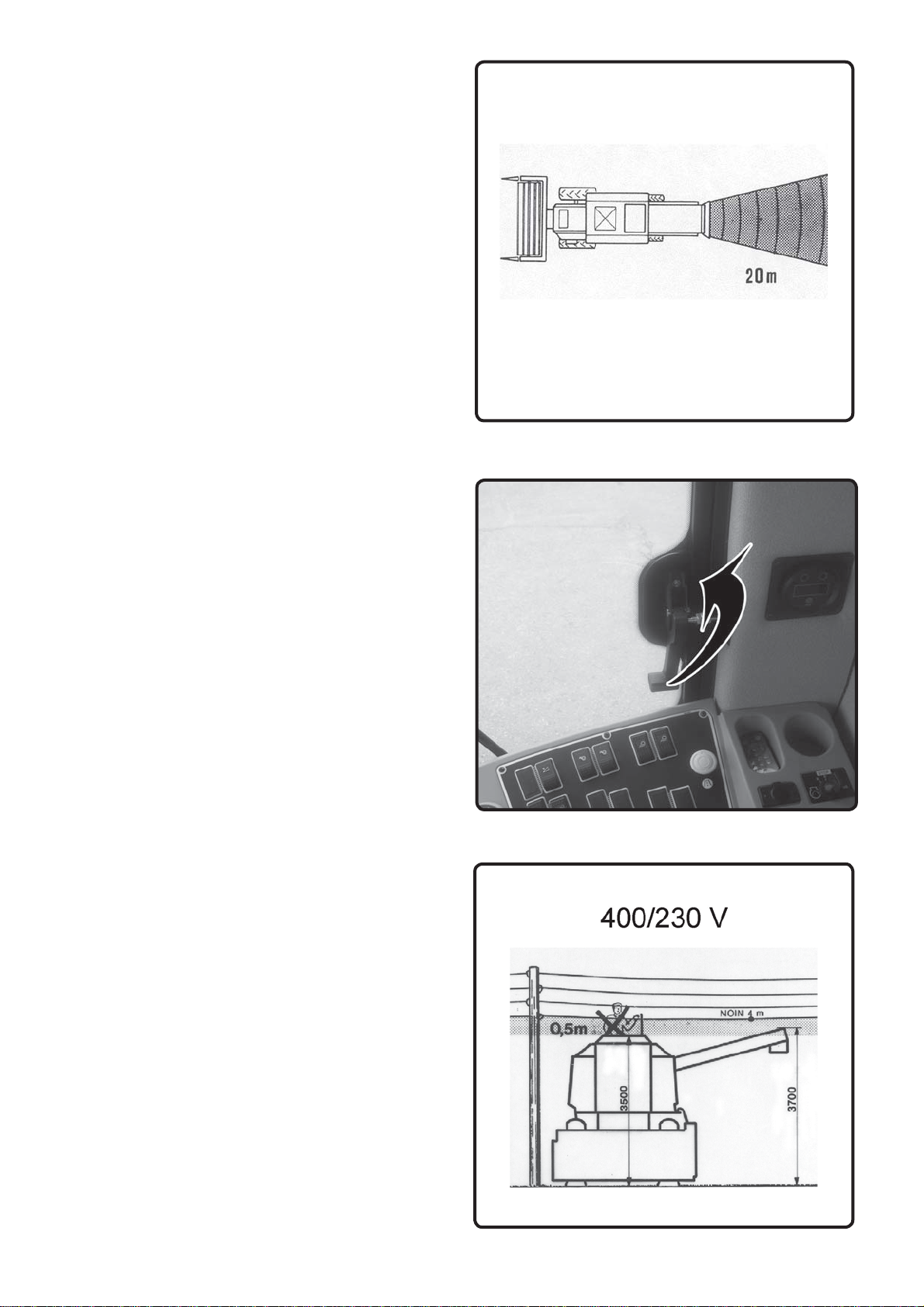
Beware of the cutting mechanism and the rotating
chopper knife.
Keep in mind that with the chopper rotating, there is a
20 m no-access danger zone behind the chopper.
Drive carefully on hillsides; the combine may overturn,
particularly with the grain tank full.
The combine cab is no safety cab.
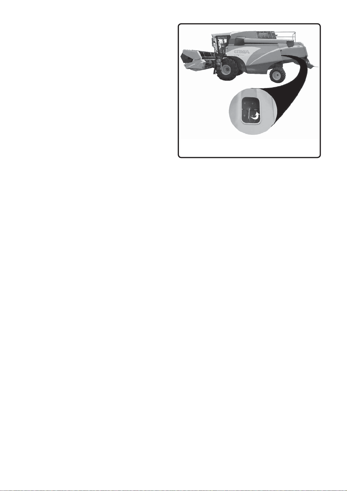
THE RIGHT-HAND SIDE DOOR MAY BE USED AS
AN EMERGENCY EXIT. PULL UP THE HANDLE,
AND OPEN THE WINDOW. Fig. EXIT
Note the recommended safety distances when thresh-
ing under power lines.
Stop the engine before cleaning or servicing the com-
bine.
Stop the combine and the engine immediately if there
is an alarm or any abnormal sounds or smells. Find out
the reason for them, and solve the problem before car-
rying on with threshing.
Support or lock the cutting table and the reel before
going beneath them.
Never clean the combine without proper equipment.
When leaving the combine, lower the cutting table,
lock the parking brake, stop the engine and remove
the ignition key.
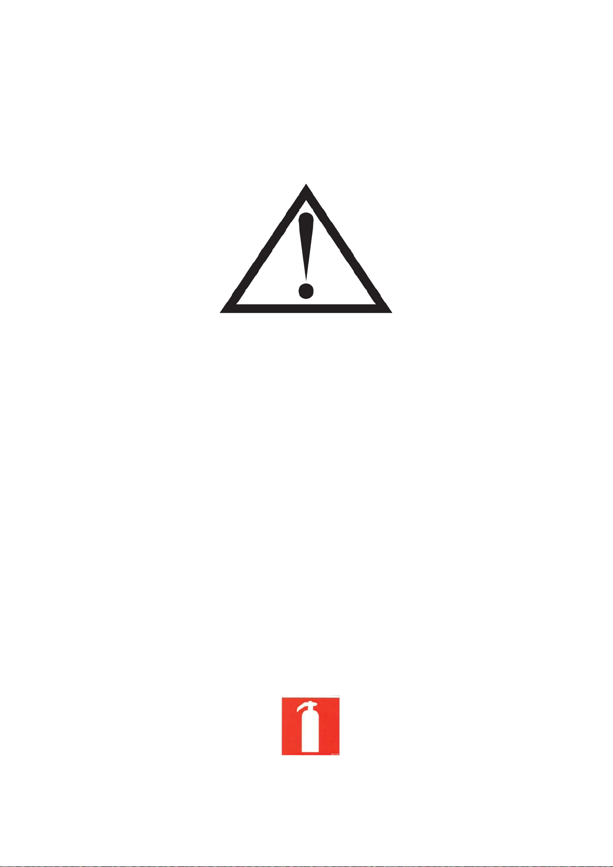
SAFETY DISTANCES WHEN THRESHING
UNDER OPEN-WIRE POWER LINES
The minimum clearance between the combine and
power lines with voltage must be in accordance with
the enclosed illustration, in which the danger zone is
darkened.
Low-voltage power lines, ¿g. A3 2404009 can be
distinguished from high-voltage line, ¿g. A4...A5 over
1 k9 by the smaller insulators and the fact that there
are usually 4 low-voltage lines.
In case the height or voltage of the power line is dif-
¿cult to estimate, the Electric Company shall be con-
sulted.

– 5 –
A4
A5
In Case of an Accident
If there is an accident despite all precautions, keep
calm and consider carefully what to do. First try to re-
verse the combine away from the power line. If there
are other people near, ask them to check that the com-
bine is not stuck in the line.
If the combine is just leaning against the lines, try to
drive it away from them. Follow the advice from the
people nearby. Due to their own safety, they shall stay
a minimum of 20 metres away from the combine touch-
ing the power line.
If the combine cannot be driven off, and you have to
leave the combine, jump down with your feet together
in order not to touch the combine and the ground
simultaneously. Do not make yourself a conductor
through which electricity can pass; the real danger lies
in touching the combine and the ground simultane-
ously. Get away from the combine jumping either with
your feet together, or with only one foot on the ground
at a time.
Otherwise the electric ¿eld on the ground may create
a fatal electric current between your legs. You will be
safe at a distance of 20 metres from the combine.
Beware of broken power lines lying on the ground.
A combine touching a power line may catch ¿re. Leave
the combine immediately if smoke starts coming from
the tyres.
Make sure the combine will be guarded at a safe dis-
tance. Do not try to get on the combine even if the
power in the power lines may seem to have gone off.
Remember that open-wire lines never have a ”blown
fuse”, but they are always dangerous unless made
dead by an electrician. Even if the power went off, it
might come back on in a while due to technical rea-
sons. This may be repeated several times.
Contact the Electric Company and inform them about
the exact site of the accident. By doing this, any risk
can be eliminated and the fault repaired.
Ask the Electric Company for advice and follow it. In-
form them about any contact with power lines even if
there was no actual damage.
SourceKoneviesti Magazine 1587

– 6 –
A6
When servicing the hydraulics, be aware of the high pressure in the system. Make sure there is no pressure in
the system or in the pressure accumulator before disconnecting the connectors.
Never use over-sized fuses; they involve risk of accident.
Never start the combine with anything but the ignition key.
When re¿tting a wheel, tighten the ¿xing screws to the correct torque.
Attach accessories such as the trailer using the appropriate equipment.
Tow the combine only from designated points.
5. THE LAWS AND REGULATIONS
Combine harvester is a complex device, and dangerous if misused. User manual must always be preserved with
the machine at the place reserved for it and if needed, new drivers should be instructed to operate the machine
Different countries have different safety at work and traf¿c regulations. Get to know the existing regulations of
your area.
4. REPAIR AND SERVICE
Always keep the combine in good condition.
Check the condition of fast moving parts daily. Pay
special attention to the transmission mechanism and
the rotating chopper knives. Replace defective parts
before they become dangerous.
Clean, repair and service the combine with the trans-
mission and engine off, the ignition key off the ignition
switch and the master switch in its off position.
Disconnect the negative battery cable before repairing
the engine or any electrical instruments.
Do not use inappropriate tools to connect and discon-
nect the battery.
Do not make an open ¿re or smoke near the battery.
Handle the battery acids with care.
Do not add air in the tyres without a pressure gauge
due to risk of explosion.
Do not add coolant with the engine running.
Do not remove the radiator cap from an overheated
engine.
Do not refuel with the engine running.
Beware of hot surfaces of the engine and exhaust pipe.
Do not smoke while fuelling.
Do not adjust the hydraulic working pressure without a
pressure gauge due to possible damage to the hoses.

– 7 –
7KLVV\PEROLQWKHPDQXDOUHIHUVWRDVSHFLDOULVNLQYROYHGLQWDNLQJDFHUWDLQPHDVXUHGXHWRZKLFKH[WUD
caution shall be practised.
6. FIRE SAFETY
Two factors are needed to start a ¿reÀammable material and ignition; oxygen is always available.
Threshing generates a lot of light and highly Àammable dust. Therefore it is important to clean the combine on a
regular basis, and the engine compartment daily.
Oil and fuel leaks increase the risk of ¿re. Repair any defects immediately.
High temperature near the exhaust pipe makes the area ¿re-prone. A ¿re may also be caused by a short circuit in
the electric system, slipping of an overloaded belt, a damaged bearing or overheating of the brakes.
Make sure there is at least one 6-kilo class AB ¿re extinguisher located in its marked place on the combine at all
times.
In particularly dry and dusty circumstances another similar extinguisher is to be placed near the engine compart-
ment.

– 8 –
MARKING THE DANGER POINTS
Although an effort has been made to build the combine as safe to use as possible, there are certain risks involved
in its use. These are to be kept in mind when operating the combine.
The danger points have been marked on the combine using hazard pictorials. On the following page you will ¿nd
the locations of and the key to these symbols. Ensure that undamaged danger markings are displayed on the
combine. The hazard pictorials are based on the international ISO 11 684 standard.

– 9 –
HAZARD PICTORIALS
Danger How to avoid it Nr. 6\PERO
Subject to danger due to
insuf¿cient information
Read the manual before starting the com-
bine 1
A raised part may fall down Support raised parts before going under
them 2
Gap in belt drive Stop the engine and remove the ignition
key before removing any guards 3
Getting entangled in mov-
ing parts
Stop the engine and remove the ignition
key before removing any guards andor
reaching into a danger zone 4
Getting entangled in rotat-
ing auge
Stop the engine and remove the ignition
key before removing any guards 5
Getting entangled in rotat-
ing auger
Do not reach into an opening with the en-
gine running 6
Falling into moving machin-
ery
Stop the engine and remove the ignition
key before removing any guards 7
Danger caused by Àying
objects
Keep at a safe distance from the combine
8
Kickback or upward motion
of arm handle
Stop the engine and remove the ignition
key before inserting the handle 9

– 10 –
TYPE MARKING
When ordering spare parts or service, always quote the type marking and number shown on he machine plate
of the combine. When ordering parts for the cutting table, also quote the type marking and number shown on the
cutting table.
When ordering engine parts, also quote the engine number.
Write down the numbers of the combine and engine on this page and in the spare part list.
Engine Number
Note! Left side of the combine = The side of the cab with the stairs
Right side of the combine = The side with the fuel tank

TECHNICAL SPECIFICATION COMIA
(ISO 6689 standard has been used in measuring)
Cutting table
Cutting width (m) 3,45 3,9 4,2 4,5 4,8 5,1
Cutting height (m) -0,20…+1,20
Knife, Number of Strokes 1020 cycles/min
Reel
Diameter (m) 1,05
Speed range (rpm) 16...51 WobbleBox (WB)
15...49 Crank-driven knife (CK)
Threshing Cylinder
Width (m) 1,11 Pre-threshing Cylinder 1,11
Diameter (m) 0,5 0,4
Number of rasp bars 7 or 8
Speed range (rpm) 600...1300 MD
400...1150 HD (Maize)
Concave
Area (m²) 0,51 Pre-Concave 0,34
Angle of wrap 105°
Number of bars 12
Clearance in front (mm) 6...42
Straw Walkers
Number 4 or 5
Separating area (m²) 4,80
Shaker Shoe (m²)
Area 3.40 m² Chaffer 1,74 + 0,33 m² Sieve 1,33 m²
Grain Tank
Volume (m³) 3,70 4,20 5,20
Unloading height (m) 3,4
4,0 (heighten unloading)
Engine AgcoSisuPower C4 C6 C8
Power kW / hp / num. of cylinders 110/150/4 136/185/6 154/210/6
RPM 2000 2000 2000
Traction Drive
Hydrostatic

Driving speed (km/h)*
Final drive Hydrostatic Traction Drive
DANA I
II
III
0... 4,7
0... 7,0
0... 18,4
4WD
4WD 0... 4,1
0... 5,6
CIT I
II
III
0… 6,4
0… 9,5
0… 25
4WD
4WD 0... 5,6
0... 7,6
* Speeds may vary depending on the size of the tyres
Turning radius (m) 5,9 (6,2 C8)
Tyres / Air pressure (bar)
Front
Tyres Weight Limit kg
5700 6000 6200 6600 6800 7100 7500 7800 8500 8600 10500
18.4- 34 157A8 1,5 1,5 1,5 1,6 1,6 1,6 1,9 1,9
18.4R34 144A8 1,5 1,5 1,5 1,6 1,6 1,6 1,9 1,9
520/70R34 148A8 1,5 1,5 1,5 1,6 1,6 1,6 1,9 1,9
600/65R34 158A8 1,2 1,2 1,2 1,3 1,3 1,4 1,5 1,8 1,9 1,9 2,0
750/65R26 166A8 1,0 1,0 1,0 1,0 1,0 1,0 1,0 1,1 1,2 1,2 1,3
800/55-30.5 172A8 0.8 0.8 0.8 0.8 0.8 0.8 1,0 1,2 1,4 1,4 1,6
Rear
Tyres Weight Limit kg
3450 5700 6000 6200 6600 6800 7100 7500 7700 8600 10500
11.5-15.3 10 PLY 1,2 1,7 1,8 1,8 1,9 1,9 2,0 2,0 2,0
360/70R20 120A8 1,6 1,7 1,7 1,8 1,8 1,8 1,9 1,9 2,0 2,0
420/65R20 125A8 1,6 1,7 1,7 1,7 1,8 1,8 1,8 1,9 1,9 1,9
550/45-22,5 153A8/149B 1,5 1,9 1,9 2,0 2,0 2,0 2,1 2,1 2,1 2,1 2,1
Wheel track (m)
Front Tyres
Final drive 18.4R34 520/70R34 600/65R34 750/65R26
DANA 2,35 / 2,52 2,35 / 2,52 2,35 / 2,52 2,55
CIT 2,35 / 2,52 2,35 / 2,52 2,35 / 2,52 2,55
Rear Tyres
Rear axle 11.5-15.3 360/70R20 420/65R20
Normal 2,2 2,42 (2,43 4WD) 2,42 (2,43 4WD)
Narrow 1,85 2,07 (2,08 4WD) 2,07 (2,08 4WD)

Volumes (See manual, LUBRICATION)
Fuel tank (litres) 200 / 350
Cooling system (litres) (4 cyl.= 29) (6 cyl =33 )
Urea (litres) 30
Weight (kg) C4 C6 C8
Without cutting table and chopper 7700 7950 8740
Cutting table (m) 3,45 3,9 4,2 4,5 4,8 5,1
Weight (kg) 790 CK 1005 1055 1110 1160 1200
890 WB
Chopper weight (kg) 190
Maize table. 4 row. (kg) 1300
Length (m) C4 C6 C8
On the road 8,7 8,7 9,1
Without cutting table 7,15 7,15 7,55
In the field 9,95 9,95 10,35
Width (m)
On the road without cutting table
Tyres
Final drive 18.4R34 520/70R34 600/65R34 750/65R26
DANA 2,82 / 2,99 2,87 / 3,04 2,95 / 3,12 3,30
CIT 2,82 / 2,99 2,87 / 3,04 2,95 / 3,12 3,30
With table (m) 3,4 3,9 4,2 4,5 4,8 5,1
3,75 4,25 4,55 4,85 5,25 5,45
Height with cabin (m) 3,7
Noise level in cabin dB(A) 78
The weighted acceleration subjected to operator's arms does not exceed 2,5 m/s² (ISO-5349)
The weighted acceleration subjected to operator's body does not exceed 0,5 m/s² (ISO-2361)

– 14 –

– 15 –
ACCEPTANCE INSPECTION AND GETTING STARTED
The combine leaves the factory packaged in an appropriate way to ensure undamaged delivery.
Before start-up the following steps shall be taken:
Read the Operating Manual carefully before start-up.
Remove all loose parts stored in the grain tank during transportation.
Make sure the combine was not damaged in transit and that no parts are missing. When necessary, contact
the dealer or the transport company.
Make sure the combine complies with the purchase agreement. When necessary, contact the dealer.
Re¿t the parts removed before transportation, such as the rotating inlet screen in the engine, lights, mirrors,
etc.
Put the ¿re extinguisher in its place.
Check the oil and coolant levels.
In case the combine has been stored for a longer period of time, change all the oils before starting harvesting.
Check and lower the tyre pressures in compliance with the recommendations given in the Operating Manual.
Make sure the threshing mechanism can rotate freely and that there are no foreign objects inside the combine
before starting the engine.
Engage the cutting table.
Assemble, ¿t and adjust the straw dividers as shown in the drawings in the Spare Parts Catalogue.
Fit the crop lifters as instructed in the Operating Manual.
Have a trial run as instructed in the item ”Storage when Not in Use”.
IMPORTANT NUMBERS
Check and write down the following numbers:
The combine serial number ___________________________
The cutting table serial number ___________________________
The engine serial number ___________________________
The cab key number ___________________________
The fuel tank key number ___________________________

– 16 –
B1
B2
OPENING THE GUARDS
To ensure safety, the movable guards in the combine
have been equipped with a locking device. They can-
not be opened without the appropriate tool supplied
with every combine, hanging on a hook on the back
wall of the cab. The guards are locked automati-
cally when closed. Some guards also have additional
clamps.
Unlock the guard at the left end of the cutting
table by turning the locking device counter-clock-
wise. To open the guard, pull the handle out-
wards and lift the guard slightly upwards at the
same time. Fig. B1.
Unlock the belt drive guard on the reel by turning
the locking device counter-clockwise. The rub-
ber clamps need to be opened ¿rst. The guard is
kept open by means of a gas spring. Fig. B1.
Open the side guards by placing the tool in the
hole at the lower part of the guard and turning
the lock open with the tool. The guard opens
when the lower edge is pulled outwards. The
guard gets locked in the upper position. It is
released from the upper position by lifting the
guard and turning the locking device open near
the gas spring. Fig. B2.

– 17 –
B3
The rear guard of the chopper straw spreaderis
released by levering the locking pivot to the right
with the tool. The guard also gets locked in the
upper position and is released correspondingly.
Choppers belt guard is opened by loosening the
bolt on the guard and turning the cover open.The
guard is secured in the upper position with a rub-
ber strip.
Straw hoods plastic cover is opened by lifting the
bottom upwards, then loose the bolts of the inner
guard and remove inner guard.

– 18 –
B7
B8
B6
Engine Compartment
To open the cover on the engine compartment
To unlock the grain tank cover, turn the lock shaft with
the key.
The cover can also be opened from the inside.
Clean, repair and service the combine with the trans-
mission and engine off, the ignition key off the ignition
switch and the master switch disconnected.
To unlock the top door to the straw walker compart-
ment remove the bolt with 13mm wrench and lift the
cover.
Other manuals for Comia c4
1
This manual suits for next models
2
Table of contents
Other Sampo Rosenlew Farm Equipment manuals