Samson SAM -01 Service manual
Other Samson Controllers manuals
Samson
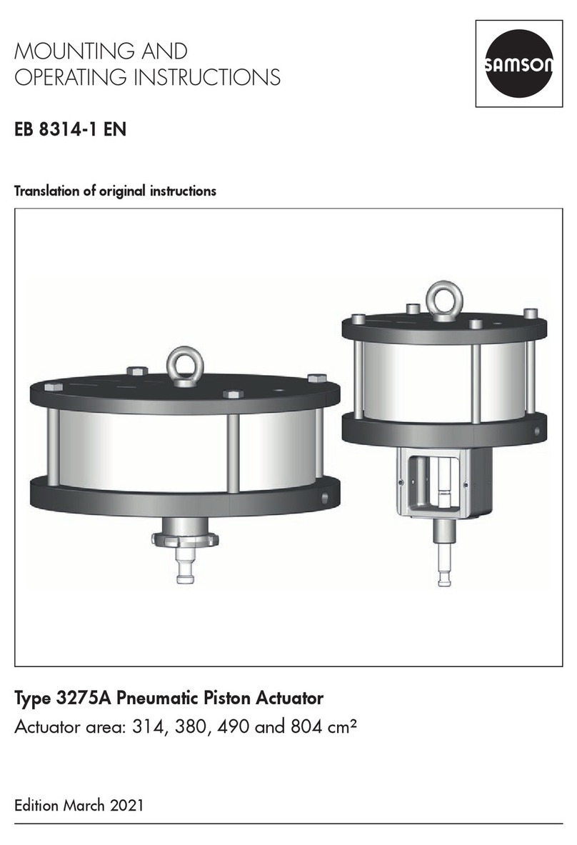
Samson 3275A Service manual

Samson
Samson 45-6 User manual
Samson
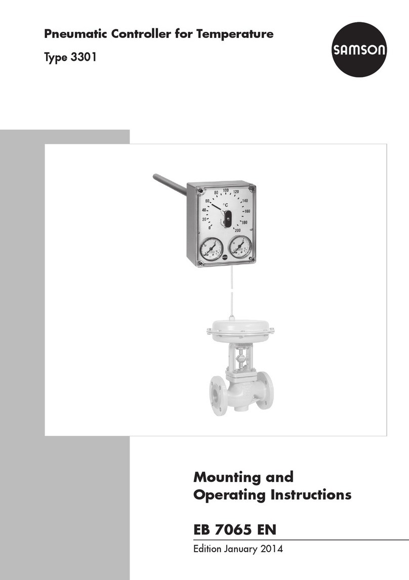
Samson 3301 Service manual
Samson
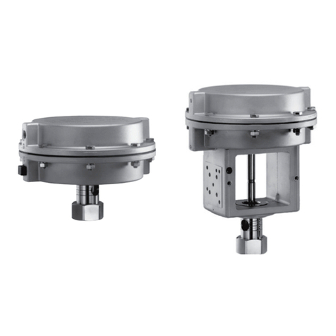
Samson 2780-1 Service manual

Samson
Samson 3273 Service manual
Samson
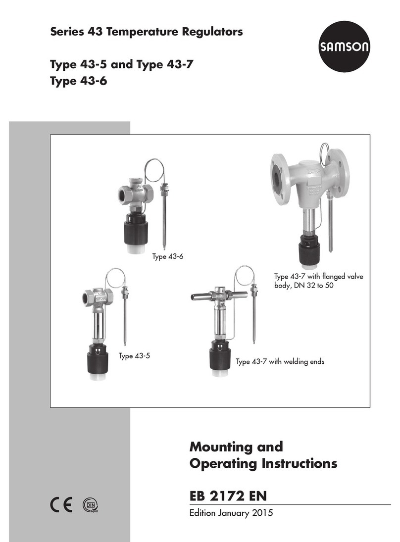
Samson 43-1 Service manual
Samson
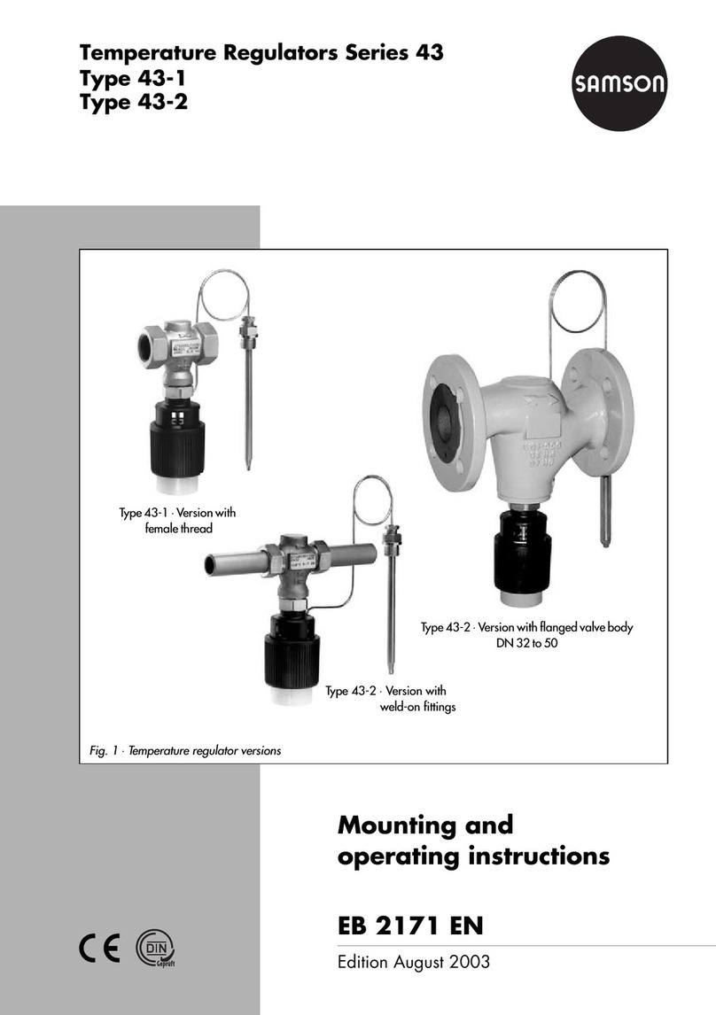
Samson series 43 Service manual

Samson
Samson 3371 Series Service manual
Samson
Samson EB 8315 EN User manual
Samson
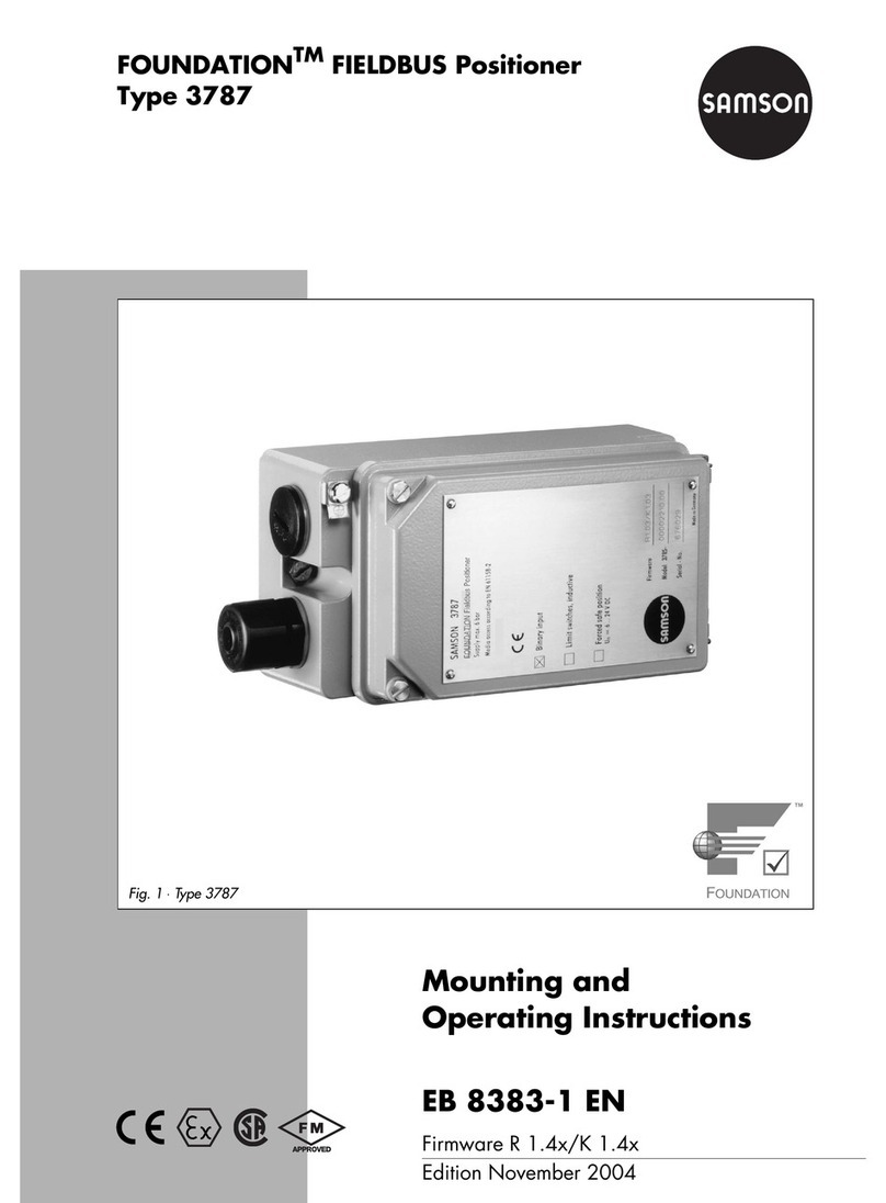
Samson foundation 3787 Service manual
Samson
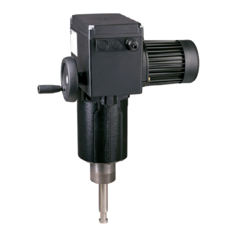
Samson 3274 Service manual
Samson
Samson 3375-10 Setup guide
Samson
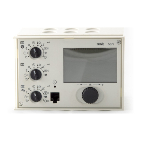
Samson TROVIS 5579 Service manual
Samson
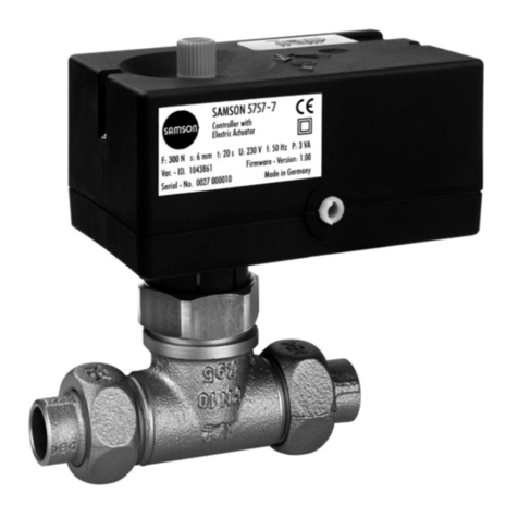
Samson TROVIS 5757-7 Service manual

Samson
Samson TROVIS 5757-7 Service manual
Samson
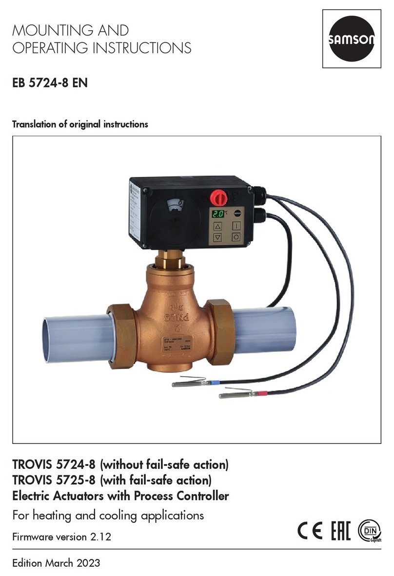
Samson TROVIS 5724-8 Service manual

Samson
Samson TROVIS 5572 Service manual
Samson
Samson TROVIS 5573 Service manual
Samson
Samson 3275 Service manual
Samson
Samson 4708-45 Service manual
Popular Controllers manuals by other brands

Digiplex
Digiplex DGP-848 Programming guide

YASKAWA
YASKAWA SGM series user manual

Sinope
Sinope Calypso RM3500ZB installation guide

Isimet
Isimet DLA Series Style 2 Installation, Operations, Start-up and Maintenance Instructions

LSIS
LSIS sv-ip5a user manual

Airflow
Airflow Uno hab Installation and operating instructions
