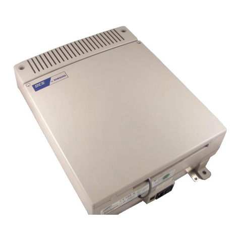
Samsung DCS Compact User manual

INSTALLATION MANUAL
CONTENTS
1
2
3
4
5
6
7
8
9
DCS
COMPACT
DIGITAL COMMUNICATION SYSTEM
SITE REQUIREMENTS
INSTALLING BASIC KSU AND
EXPANSION KIT
INSTALLING PRINTED CIRCUIT CARDS
POWER UP PROCEDURES
CONNECTING TELCO CIRCUITS
CONNECTING STATION EQUIPMENT
CONNECTING OPTIONAL EQUIPMENT
INSTALLING KEYSET DAUGHTER BOARD
CHANGING SOFTWARE

PART DESCRIPTION PAGE
1 SITE REQUIREMENTS .................................................................. 1-1
2 INSTALLATION OF BASIC KSU AND EXPANSION KIT
2.1 UNPACKING AND INSPECTION .......................................................... 2-1
2.2 KEY SERVICE UNIT INSTALLATION ................................................... 2-1
2.3 EXPANSION KIT INSTALLATION.......................................................... 2-1
2.4 GROUNDING ......................................................................................... 2-2
2.5 MDF CABLING .......................................................................................2-3
3 INSTALLING PRINTED CIRCUIT CARDS
3.1 RAM PACK .............................................................................................. 3-1
3.2 4 CO PROTECTION CARD ................................................................... 3-1
3.3 2 SLI CARD ............................................................................................. 3-1
3.4 MISC CARD............................................................................................. 3-1
3.5 4 TRK CARD............................................................................................ 3-1
3.6 6 DLI CARD............................................................................................. 3-1
3.7 6 SLI CARD.............................................................................................. 3-2
3.8 AA CARD ................................................................................................ 3-2
3.9 VDIAL CARD .......................................................................................... 3-2
3.10 AC15 CARD ............................................................................................ 3-2
3.11 BRI CARD................................................................................................ 3-2
3.12 2BRI CARD.............................................................................................. 3-2
4 POWER UP PROCEDURES
4.1 CONNECT POWER TO THE SYSTEM ................................................ 4-1
4.2 ROM CARD INDICATIONS .................................................................... 4-1
4.3 PCB VERIFICATION .............................................................................. 4-1
4.4 DEFAULT TRUNK AND STATION NUMBERING ................................. 4-1
SAMSUNG DCS INSTALLATION
TECHNICAL MANUAL TABLE OF CONTENTS APRIL 1996
i
TA B L E O F C O N T E N T S

5 CONNECTING TELCO CIRCUITS
5.1 SAFETY PRECAUTIONS ...................................................................... 5-1
5.2 LOOP START LINES .............................................................................. 5-1
5.3 OFF PREMISE EXTENSIONS (OPX) ................................................... 5-1
6 CONNECTING STATION EQUIPMENT
6.1 SAFETY PRECAUTIONS ...................................................................... 6-1
6.2 DCS COMPACT KEYSET ...................................................................... 6-1
6.3 ADD-ON MODULE ................................................................................. 6-1
6.4 SINGLE LINE TELEPHONE .................................................................. 6-1
6.5 DOOR PHONE AND DOOR LOCK RELEASE ..................................... 6-2
6.6 SIM (RS232C) .........................................................................................6-2
7 CONNECTING OPTIONAL EQUIPMENT
7.1 MUSIC ON HOLD/BACK GROUND MUSIC ......................................... 7-1
7.2 EXTERNAL PAGING .............................................................................. 7-1
7.3 COMMON BELL ..................................................................................... 7-2
7.4 RING OVER PAGE .................................................................................7-2
7.5 STATION MESSAGE DETAIL RECORDING (SMDR) .......................... 7-2
7.6 PC PROGRAMMING ............................................................................. 7-2
7.7 REMOTE PROGRAMMING ...................................................................7-3
7.8 POWER FAILURE TRANSFER (PFT) .................................................. 7-3
7.9 VOICE MAIL/AUTO ATTENDANT ......................................................... 7-4
8 INSTALLING KEYSET DAUGHTERBOARDS
8.1 KDB SLI .................................................................................................. 8-1
8.2 KDB DLI .................................................................................................. 8-1
8.3 CONNECTING TO THE KDB-S & KDB-D ............................................. 8-1
9 CHANGING SOFTWARE
9.1 ACCESSING THE EPROMS.................................................................. 9-1
9.2 REPLACING THE EPROMS .................................................................. 9-1
SAMSUNG DCS INSTALLATION
TECHNICAL MANUAL TABLE OF CONTENTS APRIL 1996
ii
PART 1. SITE REQUIREMENTS
When planning the installation of the DCS COMPACT
, choose a site that meets the following requirements:
Select a location for the key service unit (KSU) that has enough space for easy installation and
has adequate lighting (see Figure 1–1).
Select a location that will minimize cable lengths. See the Cable Requirements table below.
The equipment should not be exposed to direct sunlight, corrosive fumes, dust, constant
vibration or strong magnetic fields such as those generated by motors and copy machines.
A direct commercial AC power outlet is required. Do not use extension cords.
Preferably, a dedicated circuit should be used to minimize the risk of other electrical equipment
being connected that could adversely affect system operation.
Ensure that all wires and cable going to and coming from the KSU are properly routed. Do not
cross fluorescent lights or run parallel with AC wires.
The equipment must be located in an environment that will maintain a temperature range of
– – and a humidity range of 10%–90% non-condensing.
Allow at least 6" clearance on both sides and 6" clearance on top of the KSU to ensure proper
ventilation.
Do not install in close proximity to a fire sprinkler head or other sources of water.
Meeting these requirements will help to ensure proper performance and greater life expectancy of
the system.
*This is the maximum distance a door phone can be from the DPIM. The DPIM can be a maximum
of 900 cable feet from the KSU.
SAMSUNG DCS INSTALLATION
TECHNICAL MANUAL APRIL 1996
1–1
CABLE REQUIREMENTS
EQUIPMENT CABLE AWG MAX FEET MAX METERS
DIGITAL KEYSETS 1PR. TWISTED 24 1300 400
ADD-ON MODULES 1PR. TWISTED 24 1300 400
SINGLE LINE STATION 1PR. TWISTED 24 3000 1 KM
DOOR PHONE 2PR. TWISTED 24 330* 100
SIM 1PR TWISTED 24 1300 400

SAMSUNG DCS INSTALLATION
TECHNICAL MANUAL APRIL 1996
1–2
FIGURE 1–1
KEY SERVICE UNIT DIMENSIONS

PART 2. INSTALLING OF BASIC KSU AND
EXPANSION KIT
2.1 UNPACKING AND INSPECTION
After unpacking the KSU, inspect for signs of physical damage. If any damage is detected, do not
attempt to install. Contact Samsung Technical Support Department.
Check to see that the KSU carton includes the following items:
Key service unit
4 Central Office Protection (4 COP) card
Wall-mount kit consisting of three screws
RAM pack
Check to see that the EXPANSION KIT carton includes the following:
Expansion backplane
Plastic card rack
Vinyl bag with screws and cables
2.2 KEY SERVICE UNIT INSTALLATION
The Key Service Unit (KSU) must be wall-mounted. The KSU should be mounted on a polywood
backboard at least 5/8" thick. Attach a mounting screw to the backboard . Next hang the KSU on the
screws and secure it to the backboard with the remaining two screws (see Figure 2–1).
2.3 EXPANSION KIT INSTALLATION
1. Mount the expansion backplane in the basic KSU and attach it securely with the five screws
supplied. Take care not to over-tighten the screws and damage the PCB (see Figure 2–2).
2. Connect the expansion backplane to the basic KSU by plugging one end of the ribbon cable into
the socket on the KSU motherboard and the other end into the expansion backplane.
NOTE:It is recommended that the ribbon cable be attached to the expansion baseboard before it is
installed in the KSU.
3. Connect the ground wires from the expansion backplane to the connectors on the KSU
motherboard.
4. Fit the plastic card rack to the basic KSU and secure with the three screws that are supplied. Take
care not to over-tighten the screws and strip the threads (see Figure 2–3).
SAMSUNG DCS INSTALLATION
TECHNICAL MANUAL APRIL 1996
2–1

2.4 GROUNDING
The DCS COMPACT comes equipped ready to use with a third wire AC ground provided through
the power cord. This third wire ground will be adequate for most applications. However, if it is
suspected that there is a problem with the ground provided at the AC outlet or local codes require a
solid earth ground to be connected to the KSU, the existing third wire ground must be disconnected
before power is applied. The existing third wire ground is disconnected by removing the holding
screw and taping and storing the wire (see Figure 2–4). After this wire has been disconnected, the
grounding lug on the PSU must be connected to a ground rod or metal cold water pipe using #10
AWG solid copper wire.
Failure to provide an adequate ground may cause confusing trouble symptoms or even circuit card
failure.
2.5 MDF CABLING
All connections to the DCS COMPACT system are made by way of a customer-provided main
distribution frame (MDF). The KSU and expansion kit are each connected to the MDF using a 25
pair female amphenol-type cable. These cables can be routed into the KSU cabinet from below.
Label each cable to correspond with the connector numbers (see Figure 2–4). Label each 66
terminating block with the same connector number with which the cable is labeled.
Use one pair twisted wire to cross-connect stations or lines to their associated port.
SAMSUNG DCS INSTALLATION
TECHNICAL MANUAL APRIL 1996
2–2
WARNING: Unplug the power cord from the AC outlet before attempting to connect the
ground. Hazardous voltage may cause death or injury. Observe extreme caution
when working with AC power.

SAMSUNG DCS INSTALLATION
TECHNICAL MANUAL APRIL 1996
2–3
FIGURE 2–1
KSU MOUNTING HOLES

SAMSUNG DCS INSTALLATION
TECHNICAL MANUAL APRIL 1996
2–4
FIGURE 2–2
LOCATION OF BACKPLANE
MOUNTING SCREWS
FIGURE 2–3
LOCATION OF RACK
MOUNTING SCREWS

SAMSUNG DCS INSTALLATION
TECHNICAL MANUAL APRIL 1996
2–5
FIGURE 2–4
KEY SERVICE UNIT GROUNDING

SAMSUNG DCS INSTALLATION
TECHNICAL MANUAL APRIL 1996
PART 3. INSTALLING PRINTED CIRCUIT CARDS
Unpack and inspect each card before installing. Check for signs of physical damage. If any damage
is detected, do not attempt to install. Contact Samsung Technical Support immediately.
3.1 RAM PACK (Figure 3–2)
Select the appropriate type of RAM pack for the system. Make sure that the BACK UP switch is in
the OFF positon. Insert the RAM card in the KSU slot labeled RAM (see Figure 3–1). Push firmly in
the middle of the RAM pack to ensure that it is fully inserted into the back plane connector.
To prevent accidental damage to the RAM card, the RAM connector on the back plane is positioned
to mate only with the RAM card. Other interface cards will not mate with this connector and the RAM
card will not mate with any other connector.
3.2 4 CO PROTECTION CARD (Figure 3–3)
This card has no selectable options. Insert the 4 CO protection card into the appropriate slot (see
Figure 3–1). Push firmly in the middle of both card ejectors to ensure that it is fully inserted into the
back plane connector.
3.3 2 SLI CARD (Figure 3–4)
This card has no selectable options. Insert the 2 SLI card into the appropriate slot (see Figure 3–1).
Push firmly in the middle of both card ejectors to ensure that it is fully inserted into the back plane
connector.
3.4 MISC CARD (Figure 3–5)
There are no options to select on this card. Insert the MISC card into the appropriate slot (see Figure
3-1). Push firmly in the middle of both card ejectors on each card to ensure that it is fully inserted
into the back plane connector.
NOTE: Only one MISC card can be installed in a system.
3.5 4 TRK CARD (Figure 3–7)
There are no options to select on this card. Insert the 4 TRK card into any slot on the expansion
back plane (see Figure 3–6). Push firmly in the middle of both card ejectors on each card to ensure
that it is fully inserted into the back plane connector.
3.6 6 DLI CARD (Figure 3–7)
There are no options to select on this card. Insert the 6 DLI card into any slot on the expansion back
plane (see Figure 3–6). Push firmly in the middle of both card ejectors on each card to ensure that it
is fully inserted into the back plane connector.
3–1

SAMSUNG DCS INSTALLATION
TECHNICAL MANUAL APRIL 1996
3.7 6 SLI CARD (Figure 3–8)
There are no options to select on this card. Insert the 6 SLI card into any slot on the expansion back
plane (see Figure 3–6). Push firmly in the middle of both card ejectors on each card to ensure that it
is fully inserted into the back plane connector.
3.8 AA CARD (Figure 3–8)
There are no options to select on this card. Insert the AA card into any slot on the expansion back
plane (see Figure 3–6). Push firmly in the middle of both card ejectors on each card to ensure that it
is fully inserted into the back plane connector.
3.9 AC 15 CARD (Figure 3–9) ( U.K. only)
There are no options to select on this card. Insert the AC15 card into any slot on the expansion
back plane (see Figure 3–6). Push firmly in the middle of both card ejectors on each card to ensure
that it is fully inserted into the back plane connector.
3.10 BRI CARD (Figure 3–9)
There are no options to select on this card. Insert the BRI card into any slot on the expansion back
plane (see Figure 3–6). Push firmly in the middle of both card ejectors on each card to ensure that it
is fully inserted into the back plane connector.
3.11 2 BRI CARD (Figure 3–10)
There are no options to select on this card. Insert the 2 BRI card into any slot on the expansion
back plane (see Figure 3–6). Push firmly in the middle of both card ejectors on each card to ensure
that it is fully inserted into the back plane connector.
3.12 VDIAL CARD (Figure 3–10)
There are no options to select on this card. Insert the VDIAL card into any slot on the expansion
back plane (see Figure 3–6). Push firmly in the middle of both card ejectors on each card to ensure
that it is fully inserted into the back plane connector.
3–2

SAMSUNG DCS INSTALLATION
TECHNICAL MANUAL APRIL 1996
3–3
FIGURE 3–1
408 KSU SLOT POSITIONS

SAMSUNG DCS INSTALLATION
TECHNICAL MANUAL APRIL 1996
3–4
FIGURE 3–2
DCS COMPACT RAM PACK

SAMSUNG DCS INSTALLATION
TECHNICAL MANUAL APRIL 1996
3–5
FIGURE 3–4
2 SLI CARD
FIGURE 3–3
4 CO PROTECTION CARD

SAMSUNG DCS INSTALLATION
TECHNICAL MANUAL APRIL 1996
3–6
FIGURE 3–5
MISC CARD

SAMSUNG DCS INSTALLATION
TECHNICAL MANUAL APRIL 1996
3–7
FIGURE 3– 6
EXPANSION KIT INSTALLED
IN KSU

SAMSUNG DCS INSTALLATION
TECHNICAL MANUAL APRIL 1996
3–8
FIGURE 3–7
4 TRK CARD AND 6 DLI CARD

SAMSUNG DCS INSTALLATION
TECHNICAL MANUAL APRIL 1996
3–9
FIGURE 3–8
6 SLI CARD AND AA CARD

SAMSUNG DCS INSTALLATION
TECHNICAL MANUAL APRIL 1996
3–10
FIGURE 3–9
AC 15 AND BRI CARD
Other manuals for DCS Compact
1
Table of contents
Other Samsung Conference System manuals

Samsung
Samsung SVMi-8 User manual

Samsung
Samsung iDCS 16 Specification sheet

Samsung
Samsung SyncMaster VC240 User manual

Samsung
Samsung iDCS500 User manual

Samsung
Samsung DCS Owner's manual

Samsung
Samsung iDCS500 User manual

Samsung
Samsung DCS-816 Operating and maintenance instructions

Samsung
Samsung OFFICESERV 500 Series Operating instructions

Samsung
Samsung DCS 50si User manual

Samsung
Samsung STN-WM55R User manual