Samsung KS86C6004 User manual

Product Overview
Address Spaces
Addressing Modes
Control Registers
Interrupt Structure
SAM87RI Instruction Set

KS86C6004/C6008/P6008 MICROCONTROLLER (Preliminary Spec) PRODUCT OVERVIEW
1-1
1PRODUCT OVERVIEW
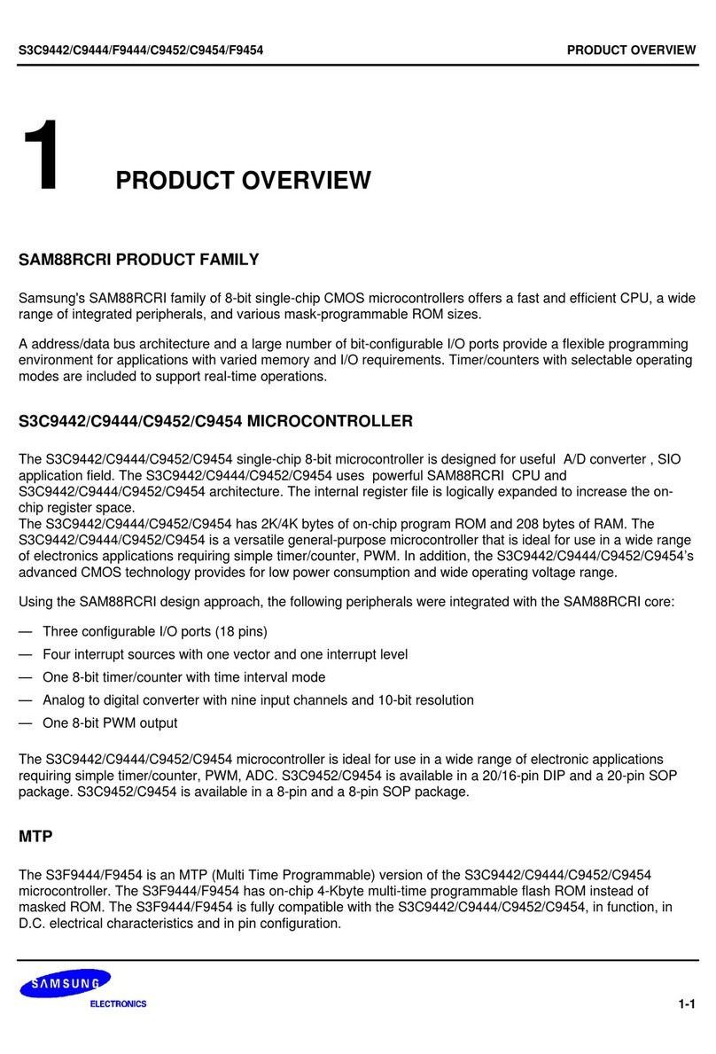
SAM87RI PRODUCT FAMILY
Samsung's SAM87RI family of 8-bit single-chip CMOS microcontrollers offers a fast and efficient CPU, a wide
range of integrated peripherals, and various mask-programmable ROM sizes.
A dual address/data bus architecture and a large number of bit- or nibble-configurable I/O ports provide a flexible
programming environment for applications with varied memory and I/O requirements. Timer/counters with
selectable operating modes are included to support real-time operations. Many SAM87RI microcontrollers have
an external interface that provides access to external memory and other peripheral devices.
KS86C6004/C6008/P6008 MICROCONTROLLER
The KS86C6004/C6008/P6008 single-chip 8-bit microcontroller is fabricated using an advanced CMOS process.
It is built around the powerful SAM87RI CPU core.
Stop and Idle power-down modes were implemented to reduce power consumption. To increase on-chip register
space, the size of the internal register file was logically expanded. The KS86C6004 has 4 K bytes of program
memory on-chip and KS86C6008 has 8 K bytes.
Using the SAM87RI design approach, the following peripherals were integrated with the SAM87RI core:
— Five configurable I/O ports (32 pins)
— 12 bit-programmable pins for external interrupts
— 8-bit timer/counter with three operating modes
— Low speed USB function
The KS86C6004/C6008/P6008 is a versatile microcontroller that can be used in a wide range of low speed USB
support general purpose applications. It is especially suitable for use as a keyboard controller and is available in
a 42-pin SDIP and a 44-pin QFP package.
OTP
The KS86C6004/C6008 microcontroller is also available in OTP (One Time Programmable) version,
KS86P6008. KS86P6008 microcontroller has an on-chip 8-Kbyte one-time-programmable EPROM instead of
masked ROM. The KS86P6008 is comparable to KS86C6004/C6008, both in function and in pin configuration.

PRODUCT OVERVIEW KS86C6004/C6008/P6008 MICROCONTROLLER (Preliminary Spec)
1-2
FEATURES
CPU
• SAM87RI CPU core
Memory
• 8-Kbyte internal program memory (ROM)
• 208-byte RAM
Instruction Set
• 41 instructions
• IDLE and STOP instructions added for power-
down modes
Instruction Execution Time
•1.0µs at 6 MHz fOSC
Interrupts
• 25 interrupt sources with one vector, each
source has its pending bit
• One level, one vector interrupt structure
Oscillation Circuit
• 6 MHz crystal/ceramic oscillator
• External clock source (6 MHz)
General I/O
• Bit programmable five I/O ports (32 pins total)
Timer/Counter
• One 8-bit basic timer for watchdog function and
programmable oscillation stabilization interval
generation function
• One 8-bit timer/counter with Compare/Overflow
USB Serial Bus
• Compatible to USB low speed (1.5 Mbps) device
1.0 specification.
• Serial bus interface engine (SIE)
— Packet decoding/generation
— CRC generation and checking
— NRZI encoding/decoding and bit-stuffing
• 8 bytes each receive/transmit USB buffer
Operating Temperature Range
•–40
°C to + 85°C
Operating Voltage Range
• 4.5 V to 5.5 V
Package Types
• 42-pin SDIP
• 44-pin QFP

KS86C6004/C6008/P6008 MICROCONTROLLER (Preliminary Spec) PRODUCT OVERVIEW
1-3
BLOCK DIAGRAM
PORT 0
PORT 3
SAM87RI CPU
P0.0
k
0.7/INT2
8-KB ROM
P3.0
P3.1
P3.2
P3.3/CLO
OSC
224-BYTE
REGISTER
PORT 4
P4.0 / INT1
P4.1 / INT1
P4.2 / INT1
P4.3 / INT1
TIMER 0
PORT 1 PORT 2
P2.0
k
2.7 / INT0
P1.0
k
1.7
XIN
XOUT
SAM87RI BUS
BASIC
TIMER
I/O PORT AND
INTERRUPT CONTROL
USB D+
D-
3.3 VOUT
16 bytes
USB
Buffer
Figure 1-1. Block Diagram

PRODUCT OVERVIEW KS86C6004/C6008/P6008 MICROCONTROLLER (Preliminary Spec)
1-4
PIN ASSIGNMENTS
P3.1
P3.0
INT0 / P2.0
INT0 / P2.1
INT0 / P2.2
INT0 / P2.3
INT0 / P2.4
INT0 / P2.5
INT0 / P2.6
INT0 / P2.7
VDD
VSS1
XOUT
XIN
TEST
INT1 / P4.0
INT1 / P4.1
RESET
INT1 / P4.2
INT1 / P4.3
P1/7
KS86C6004
KS86C6008
42-SDIP
(Top View)
1
2
3
4
5
6
7
8
9
10
11
12
13
14
15
16
17
18
19
20
21
P3.2
P3.3/CLO
D+
D-
3.3 VOUT
VSS2
P0.0 / INT2
P0.1 / INT2
P0.2 / INT2
P0.3 / INT2
P0.4 / INT2
P0.5 / INT2
P0.6 / INT2
P0.7 / INT2
P1.0
P1.1
P1.2
P1.3
P1.4
P1.5
P1.6
42
41
40
39
38
37
36
35
34
33
32
31
30
29
28
27
26
25
24
23
22
Figure 1-2. Pin Assignment Diagram (42-Pin SDIP Package)

KS86C6004/C6008/P6008 MICROCONTROLLER (Preliminary Spec) PRODUCT OVERVIEW
1-5
3.3 VOUT
D-
D+
P3.3/CLO
P3.2
P3.1
P3.0
P2.0/INT0
P2.1/INT0
P2.2/INT0
P2.3/INT0
P1.0
P1.1
P1.2
P1.3
P1.4
P1.5
P1.6
P1.7
P4.3/INT1
P4.2/INT1
RESET
NC
NC
VSS2
P0.0/INT2
P0.1/INT2
P0.2/INT2
P0.3/INT2
P0.4 /INT2
P0.5/INT2
P0.6/INT2
P0.7/INT2
INT0 / P2.4
INT0 / P2.5
INT0 / P2.6
INT0 / P2.7
VDD
VSS1
XOUT
XIN
TEST
P4.0/INT1
P4.1/INT1
34
35
36
37
38
39
40
41
42
43
44
22
21
20
19
18
17
16
15
14
13
12
KS86C6004
KS86C6008
(Top View)
1
2
3
4
5
6
7
8
9
10
11
33
32
31
30
29
28
27
26
25
24
23
Figure 1-3. Pin Assignment Diagram (44-Pin QFP Package)

PRODUCT OVERVIEW KS86C6004/C6008/P6008 MICROCONTROLLER (Preliminary Spec)
1-6
PIN DESCRIPTIONS
Table 1-1. KS86C6004/C6008/P6008 Pin Descriptions
Pin
Names Pin
Type Pin
Description Circuit
Number Pin
Numbers Share
Pins
P0.0-P0.7 I/O Bit-programmable I/O port for Schmitt trigger
input or open-drain output. Port0 can be
individually configured as external interrupt
inputs. Pull-up resistors are assignable by
software.
B 36–29
(30–23) INT2
P1.0-P1.7 I/O Bit-programmable I/O port for Schmitt trigger
input or open-drain output. Pull-up resistors are
assignable by software.
B 28–21
(22–15) –
P2.0-P2.7 I/O Bit-programmable I/O port for Schmitt trigger
input or open-drain output. Port2 can be
individually configured as external interrupt
inputs. Pull-up resistors are assignable by
software.
B 3–10
(41–44, 1–4) INT0
P3.0-P3.3 I/O Bit-programmable I/O port for Schmitt trigger
input, open-drain or push-pull output. P3.3 can
be used to system clock output(CLO) pin.
C 2, 1, 42, 41
(40–37) P3.3/CLO
P4.0-P4.3 I/O Bit-programmable I/O port for Schmitt trigger
input or open-drain output or push-pull output.
Port4 can be individually configured as external
interrupt inputs. In output mode, pull-up resistors
are assignable by software. But in input mode,
pull-up resistors are fixed.
D 16, 17, 19, 20
(10, 11, 13,
14)
INT1
D+/D- I/O Only be used USB tranceive/receive port; D+/D-. – 40–39 (36-35) –
3.3 VOUT –3.3 V output from internal voltage regulator – 38 (34) –
XIN, XOUT –System clock input and output pin
(crystal/ceramic oscillator, or external clock
source)
– 14, 13
(8, 7) –
INT0
INT1
INT2
I External interrupt for bit-programmable port0,
port2 and port4 pins when set to input mode. –3–10, 16,17,
19, 20, 29–36
(30–23, 41–
44, 1–4, 10,
11, 13, 14)
PORT2/
PORT4/
PORT0
RESET IRESET signal input pin. Schmitt trigger input with
internal pull-up resistor. A 18 (12) –
TEST I Test signal input pin (for factory use only; must
be connected to VSS)– 15 (9) –
VDD – Power input pin – 11 (5) –
VSS1,VSS2 – Vss1 is a ground power for CPU core.
Vss2 is a ground power for I/O and OSC block. – 12, 37
(6, 31) –
NC – No connection – –
(32, 33) –
NOTE: Pin numbers shown in parenthesis '( )' are for the 44-QFP package; others are for the 42-SDIP package.

KS86C6004/C6008/P6008 MICROCONTROLLER (Preliminary Spec) PRODUCT OVERVIEW
1-7
PIN CIRCUITS
Table 1-2. Pin Circuit Assignments for the KS86C6004/C6008/P6008
Circuit Number Circuit Type KS86C6004/C6008/P6008 Assignments
AI
RESET signal input
B I/O Ports 0, 1, and 2
C I/O Port 3
D I/O Port 4
VDD
PULL-UP
RESISTOR
IN Noise
Filter
Figure 1-4. Pin Circuit Type A (RESET)
OUTPUT
DISABLE
INPUT
DATA MUX D0
D1
MODE INPUT DATA
INPUT
OUTPUT D0
D1
I/O
PULL-UP ENABLE
VSS
VDD
PULL-UP
RESISTOR
OUTPUT
DATA
Figure 1-5. Pin Circuit Type B (Ports 0, 1 and 2)

PRODUCT OVERVIEW KS86C6004/C6008/P6008 MICROCONTROLLER (Preliminary Spec)
1-8
VDD
OPEN
DRAIN
OUTPUT
DISABLE
INPUT
DATA
MODE INPUT DATA
INPUT
OUTPUT D0
D1
I/O
OUTPUT
DATA
VSS
MUX D0
D1
Figure 1-6. Pin Circuit Type C (Port 3)

KS86C6004/C6008/P6008 MICROCONTROLLER (Preliminary Spec) PRODUCT OVERVIEW
1-9
VDD
OPEN
DRAIN
OUTPUT
DISABLE
INPUT
DATA
MODE INPUT DATA
INPUT
OUTPUT D0
D1
I/O
OUTPUT
DATA
VSS
PULL-UP
ENABLE
VDD
PULL-UP
RESISTOR
MUX D0
D1
Figure 1-7. Pin Circuit Type D (Port 4)

PRODUCT OVERVIEW KS86C6004/C6008/P6008 MICROCONTROLLER (Preliminary Spec)
1-10
APPLICATION CIRCUIT
KEYBOARD
MATRIX
0
1
2
3
15
0
1
2
3
7
5V
H
O
S
T
5V
XOUT
XIN
VSS1 VSS2
VDD
PORT 3
PORT 0PORT 1PORT 2
TEST
RESET
D+
D-
KS86C6004
KS86C6008
Figure 1-8. Keyboard Application Circuit Diagram

KS86C6004/C6008/P6008 MICROCONTROLLER (Preliminary Spec) ADDRESS SPACES
2-1
2ADDRESS SPACES
OVERVIEW
The KS86C6004/C6008/P6008 microcontroller has two kinds of address space:
— Program memory (ROM), internal
— Internal register file
A 13-bit address bus supports both program memory. A separate 8-bit register bus carries addresses and data
between the CPU and the internal register file.
The KS86C6004 has 4 K bytes of mask-programmable program memory on-chip and KS86C6008 has 8 K bytes.
There is one program memory configuration option:
— Internal ROM mode, in which only the 8-Kbyte internal program memory is used.
The KS86C6004/C6008/P6008 microcontroller has 208 general-purpose registers in its internal register file.
Twenty-seven bytes in the register file are mapped for system and peripheral control functions.

ADDRESS SPACES KS86C6004/C6008/P6008 MICROCONTROLLER (Preliminary Spec)
2-2
PROGRAM MEMORY (ROM)
Normal Operating Mode (Internal ROM)
The KS86C6004 has 4 K bytes (locations 0H–0FFFH) of internal mask-programmable program memory. The
KS86C6008/P6008 has 8 K bytes (locations 0H–1FFFH) of internal mask-programmable program memory.
The first 2 bytes of the ROM (0000H–0001H) are an interrupt vector address.
The program reset address in the ROM is 0100H.
(DECIMAL) (HEX)
1FFFH (KS86C6008/P6008)8,191
2
1
0
0002H
0001H
0000H
Interrupt vector
8-KBYTE
INTERNAL
PROGRAM
MEMORY
AREA
256 Program start 0100H
4-KBYTE
INTERNAL
PROGRAM
MEMORY
AREA
0FFFH (KS86C6004)4,095
Figure 2-1. Program Memory Address Space

KS86C6004/C6008/P6008 MICROCONTROLLER (Preliminary Spec) ADDRESS SPACES
2-3
REGISTER ARCHITECTURE
The upper 64 bytes of the KS86C6004/C6008/P6008's internal register file are addressed as working registers,
system control registers and peripheral control registers. The lower 192 bytes of internal register file (00H–BFH)
is called the
general purpose register space
. The total addressable register space is thereby 256 bytes. 233
registers in this space can be accessed.; 208 are available for general-purpose use.
For many SAM87RI microcontrollers, the addressable area of the internal register file is further expanded by the
additional of one or more register pages at general purpose register space (00H–BFH). This register file
expansion is not implemented in the KS86C6004/C6008/P6008, however. Page addressing is controlled by the
System Mode Register (SYM.1–SYM.0).
The specific register types and the area (in bytes) that they occupy in the internal register file are summarized in
Table 2-1.
Table 2-1. Register Type Summary
Register Type Number of Bytes
CPU and system control registers 11
Peripheral, I/O, and clock control and data registers 26
General-purpose registers (including the 16-bit
common working register area) 208
Total Addressable Bytes 245

ADDRESS SPACES KS86C6004/C6008/P6008 MICROCONTROLLER (Preliminary Spec)
2-4
WORKING REGISTERS
E0H
C0H
CFH
DFH
D0H
BFH
00H
FFH
SYSTEM CONTROL
REGISTERS
GENERAL PURPOSE
REGISTER FILE
and STACK AREA
192
BYTES
64 BYTES OF
COMMON AREA
PERIPHERAL CONTROL
REGISTERS
Figure 2-2. Internal Register File Organization

KS86C6004/C6008/P6008 MICROCONTROLLER (Preliminary Spec) ADDRESS SPACES
2-5
COMMON WORKING REGISTER AREA (C0H–CFH)
The SAM87RI register architecture provides an efficient method of working register addressing that takes full
advantage of shorter instruction formats to reduce execution time.
This 16-byte address range is called
common area
. That is, locations in this area can be used as working
registers by operations that address any location on any page in the register file. Typically, these working
registers serve as temporary buffers for data operations between different pages. However, because the
KS86C6004/C6008/P6008 uses only page 0, you can use the common area for any internal data operation.
The Register (R) addressing mode can be used to access this area
Registers are addressed either as a single 8-bit register or as a paired 16-bit register. In 16-bit register pairs, the
address of the first 8-bit register is always an even number and the address of the next register is an odd
number. The most significant byte of the 16-bit data is always stored in the even-numbered register; the least
significant byte is always stored in the next (+ 1) odd-numbered register.
MSB LSB
Rn Rn + 1
n = EVEN ADDRESS
Figure 2-3. 16-Bit Register Pairs
☞PROGRAMMING TIP — Addressing the Common Working Register Area
As the following examples show, you should access working registers in the common area, locations C0H–CFH,
using working register addressing mode only.
Examples: 1. LD 0C2H,40H ; Invalid addressing mode!
Use working register addressing instead:
LD R2,40H ; R2 (C2H) ← the value in location 40H
2. ADD 0C3H,#45H ; Invalid addressing mode!
Use working register addressing instead:
ADD R3,#45H ; R3 (C3H) ←R3 + 45H

ADDRESS SPACES KS86C6004/C6008/P6008 MICROCONTROLLER (Preliminary Spec)
2-6
SYSTEM STACK
KS86-series microcontrollers use the system stack for subroutine calls and returns and to store data. The PUSH
and POP instructions are used to control system stack operations. The KS86C6004/C6008/P6008 architecture
supports stack operations in the internal register file.
Stack Operations
Return addresses for procedure calls and interrupts and data are stored on the stack. The contents of the PC are
saved to stack by a CALL instruction and restored by the RET instruction. When an interrupt occurs, the contents
of the PC and the FLAGS register are pushed to the stack. The IRET instruction then pops these values back to
their original locations. The stack address is always decremented
before
a push operation and incremented
after
a pop operation. The stack pointer (SP) always points to the stack frame stored on the top of the stack, as shown
in Figure 2-4.
STACK CONTENTS
AFTER A CALL
INSTRUCTION
PCH
PCL
HIGH ADDRESS
PCH
TOP OF
STACK
PCL
FLAGS
STACK CONTENTS
AFTER AN
INTERRUPT
TOP OF
STACK
LOW ADDRESS
Figure 2-4. Stack Operations
Stack Pointer (SP)
Register location D9H contains the 8-bit stack pointer (SP) that is used for system stack operations. After a reset,
the SP value is undetermined.
Because only internal memory space is implemented in the KS86C6004/C6008/P6008, the SP must be initialized
to an 8-bit value in the range 00H–BFH.
NOTE
In case a Stack Pointer is initialized to 00H, it is decreased to FFH when stack operation starts. This
means that a Stack Pointer access invalid stack area.

KS86C6004/C6008/P6008 MICROCONTROLLER (Preliminary Spec) ADDRESS SPACES
2-7
☞PROGRAMMING TIP — Standard Stack Operations Using PUSH and POP
The following example shows you how to perform stack operations in the internal register file using PUSH and
POP instructions:
LD SP,#0C0H ; SP ←C0H (Normally, the SP is set to 0C0H by the
; initialization routine)
•
•
•
PUSH SYM ; Stack address 0BFH ←SYM
PUSH CLKCON ; Stack address 0BEH ←CLKCON
PUSH 20H ; Stack address 0BDH ←20H
PUSH R3 ; Stack address 0BCH ←R3
•
•
•
POP R3 ; R3 ←Stack address 0BCH
POP 20H ; 20H ←Stack address 0BDH
POP CLKCON ; CLKCON ←Stack address 0BEH
POP SYM ; SYM ←Stack address 0BFH

ADDRESS SPACES KS86C6004/C6008/P6008 MICROCONTROLLER (Preliminary Spec)
2-8
NOTES

KS86C6004/C6008/P6008 MICROCONTROLLER (Preliminary Spec) ADDRESSING MODES
3-1
3ADDRESSING MODES
OVERVIEW
Instructions that are stored in program memory are fetched for execution using the program counter. Instructions
indicate the operation to be performed and the data to be operated on. Addressing mode is the method used to
determine the location of the data operand. The operands specified in SAM87RI instructions may be condition
codes, immediate data, or a location in the register file, program memory, or data memory.
The SAM87RI instruction set supports six explicit addressing modes. Not all of these addressing modes are
available for each instruction. The addressing modes and their symbols are as follows:
— Register (R)
— Indirect Register (IR)
— Indexed (X)
— Direct Address (DA)
— Relative Address (RA)
— Immediate (IM)
This manual suits for next models
2
Table of contents
Other Samsung Microcontroller manuals

Samsung
Samsung S3C8248 User manual

Samsung
Samsung S3C9454B User manual

Samsung
Samsung S3F80P5X User manual

Samsung
Samsung ARTIK 053s Installation manual

Samsung
Samsung SAM88RCRI S3C9442 User manual

Samsung
Samsung S3C8275X User manual

Samsung
Samsung S3P80C5 User manual

Samsung
Samsung S3F84B8 User manual

Samsung
Samsung S3C9228 User manual

Samsung
Samsung S3C80M4/F80M4 User manual