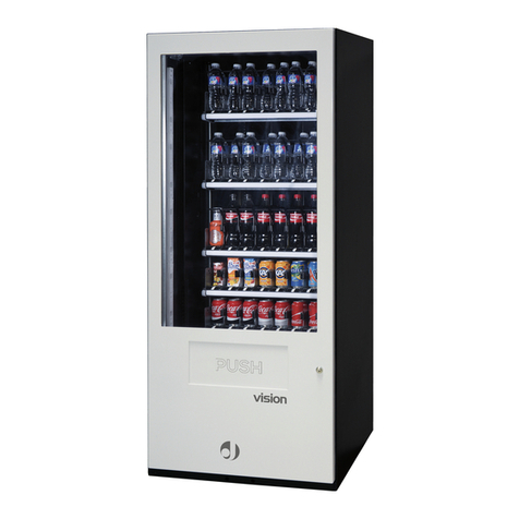
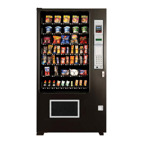
Sanden Vendo SVE 100 Operating instructions

© Date: 07/03/2014 - Revision: 3 - Code: 394799
User and maintenance manual
Superstack SVE 100 - SVE 189 - SVE 217 - SVE 254
SandenVendo Europe S.p.A.
Regione Cavallino,2
15030 Coniolo (AL) - Italy
Tel. +39 0142.335111
Fax +39 0142.562348
E-mail: [email protected]
website: www.sandenvendo.com

Sanden International (Europe) Limited
SandenVendo Italian Branch (SVI)
Regione Cavallino, 2
15030 Coniolo (AL) Italy
Tel.:+ 39 0142 335111
Fax.:+ 39 0142 562348
e-mail: [email protected]
www.sandenvendo.com
SandenVendo German Branch (SVG)
Spangerstrasse 22
40599 Dusseldorf
Germany
Tel.: + 49 211 740390
Fax: + 49 211 7488541
e-mail: [email protected]
SandenVendo Spain Sucursal en Espana (SVS)
Poligono Industrial la Almeda
C/. Sant Ferrán, no. 92
E-08940 Cornella (Barcelona) - Spain
Tel. : +34 (0)93 4741555
Fax : +34 (0)93 4741842
e-mail: [email protected]
SandenVendo Benelux (SVB)
Avenue A. Van Oss 1 - Boîte 21
1120 Bruxelles - Belgium
Tel.: +32 (0)2 2682595
Fax :+32 (0)2 2682862
e-mail: [email protected]
For France:
Jean-François Suteau: Tel: +33 6 67 38 43 26
Michel Mirczewski: Tel: +33 6 11 01 67 65
mmirczewski@sandenvendo.be
Philippe Mirczewski: Tel: +33 6 89 15 19 52
Tel. +33 1 73 06 98 54
SAV: 08 92 00 12 49 (1) numéro payant 0,34 cts la minute

Instructions for the installer, maintenance
technician and final user
1
© SandenVendo Europe SpA
INDEX
1 GENERAL INFORMATION ..............................................................................................2
1.1 Purpose of Manual........................................................................................................2
1.2 Interested people ..........................................................................................................2
1.3 Responsibility................................................................................................................4
1.4 Manufacturer.................................................................................................................5
1.5 Service Centres ............................................................................................................5
1.6 Warranty .......................................................................................................................5
1.7 General safety warnings ...............................................................................................6
1.8 Symbols .........................................................................................................................9
2 MACHINE PARTICULARS ............................................................................................10
2.1 Technical particulars ....................................................................................................10
2.2 Description of components ..........................................................................................11
2.3 Coin introduction –selection panel ..............................................................................12
2.4 Control box ..................................................................................................................12
2.5 Cooling system ............................................................................................................13
2.6 Vending mechanism ....................................................................................................13
3 INSTALLATION .............................................................................................................14
3.1 Transport and positioning ............................................................................................14
3.2 Installation environment characteristics .......................................................................15
3.3 Removing the wooden bases.......................................................................................15
3.4 Levelling.......................................................................................................................15
3.5 Stability .......................................................................................................................16
3.6Connection to the power mains ....................................................................................17
3.7 Installing the coin mechanism......................................................................................18
3.8 Control settings............................................................................................................19
3.9 Price setting .................................................................................................................19
3.10 Label installation ........................................................................................................19
4 ACCESS TO THE INTERNAL PART .............................................................................20
5 USING THE VENDING MACHINE .................................................................................21
5.1 Warnings......................................................................................................................21
5.2 Final check...................................................................................................................26
5.3 Control settings............................................................................................................26
5.4 Start up ........................................................................................................................26
6 MAINTENANCE .............................................................................................................27
6.1 Preventive maintenance ..............................................................................................27
6.2 Preventive maintenance ..............................................................................................27
6.3 Replacing neon lamps .................................................................................................28
6.4 Cleaning the vending machine.....................................................................................29
6.5 Warnings......................................................................................................................29
6.6 General cleaning operation..........................................................................................30
6.7 Recommended cleaning products ...............................................................................31
6.8 Cleaning safety device.................................................................................................31
7 INFORMATION –DANGER SIGNS ...............................................................................32
8 TROUBLESHOOTING ...................................................................................................34
9 STORAGE AND DISPOSAL ..........................................................................................36
9.1 Storage ........................................................................................................................36
9.2 Disposal .......................................................................................................................36
9.3 Person in charge of disposal........................................................................................37
9.4 Sanctions .....................................................................................................................37

Instructions for the installer, maintenance
technician and final user
2
© SandenVendo Europe SpA
1 GENERAL INFORMATION
1.1 Purpose of Manual
The manual contains the correct procedures for
loading, usage, regular and extra-ordinary
maintenance and installation of vending
machines. This manual is a very important part of
the vendor and therefore must be kept intact and
available for the whole productive life of the
vendor.
KEEP INSIDE THE MACHINE
1.2 Interested people
This manual is for the persons in charge of
loading, cleaning and ordinary maintenance of
the machine. (Loading Operator), the final user
(User)) and the people involved in installing,
setting, extraordinary maintenance of the vendor
(Installer/Maintenance Technician). The
persons in charge must know the instructions
and comply with the procedure of the manual.

Instructions for the installer, maintenance
technician and final user
3
© SandenVendo Europe SpA
Technicians allowed to operate one this
vending machines
Operator (person who only loads the machine
with products to be sold)
oThe operator can only load products to be
sold in the vending machine.
oDoing this operation the operator should
never move the protective lower carter as
indicated on the related safety icon-label on
the protection.
Maintenance Engineer / Skilled technician
oIn order to perform all the operations
requiring to dismount the protective lower
carte, it is necessary to contact only
SandenVendo technicians or only authorized
(by SandenVendo) skilled and prepared
technicians due to the potential electrical and
mechanical risks.
This appliance can be used by children aged
from 8 years and above and persons with
reduced physical, sensory or mental capabilities
or lack of experience and knowledge if they have

Instructions for the installer, maintenance
technician and final user
4
© SandenVendo Europe SpA
been given supervision or instruction concerning
use of the appliance in a safe way and
understand the hazards involved. Children shall
not play with the appliance. Cleaning and user
maintenance shall not be made by children
without supervision.
1.3 Responsibility
The responsibility of the manufacturer is limited
to the correct usage of the vendor
“SandenVendo Europe S.p.A” declines any
responsibility for possible damages caused to
people and/or things as a result of:
-Incorrect installation.
-Usage of unoriginal spare parts.
-Unforeseen modifications/authorized by
manufacturer.
-Improper use of vendor
-Connection to inadeguate supply system and
not in conformity with the regulations in force

Instructions for the installer, maintenance
technician and final user
5
© SandenVendo Europe SpA
1.4 Manufacturer
“SandenVendo Europe S.p.A.” claims more
than 50 years of experience in the manufacturing
of Vending machines, and it is the technical
know-how acquired, after years of researches
and close contact with the production and
commercialisation at global level that represents
the best warranty SandenVendo Europe S.p.A.
can offer
1.5 Service Centres
“SandenVendo Europe S.p.A.” is represented
by a solid and prepared Sales network not only in
Italy but also in Europe (see cover page).
1.6 Warranty
The warranty of the vending machine
components, starting from the date shown on the
delivery note, is 24 months for the cooling unit.
The warranty covers exclusively replaced parts,
with labour excluded.

Instructions for the installer, maintenance
technician and final user
6
© SandenVendo Europe SpA
The warranty does not include, damages to the
vendor caused by:
Transport and/or handling
Operator errors
Lack of maintenance contemplated for in this
Manual
Failures and/or breakages not caused by the
malfunction of the vending machine
1.7 General safety warnings
Carefully read the manual before starting or
loading the vendor
Protect the vendor against weather conditions
Do not remove the protection cover unless you
are a maintenance technician
Do not change the setting of the electronic
board before reading this manual
Do not place the vendor under direct sunlight
Do not sell products with the door open
Refer to routine maintenance chapter for
cleaning the vendor
Disconnect the power cable before doing
assistance or freeing a jammed product
Use a special protection system

Instructions for the installer, maintenance
technician and final user
7
© SandenVendo Europe SpA
The vendor must be installed in a way that the
electric plug is accessible after installation
If the power cable is damaged, it should be
substituted by the manufacturer or by his after-
sales technicians or however by an equally
qualified person, in order to avoid any risks
The vendor should not be installed in an area
where water jets are used
The vendor should not be installed outdoor
To preventy hazards due to machine
instability,secure the machine according to the
instructions
In case of failure and/or poor operation, please
contact exclusively the qualified personnel of
our service centres
Use only spare parts authorised by the
manufacturer
Should this manual be lost or damages, you
may ask for a copu from the manufacturer,
enclose the serial number of your vending
machine with youur request

Instructions for the installer, maintenance
technician and final user
8
© SandenVendo Europe SpA
CAUTION: FAILURE TO ABIDE BY THE
INSTRUCTIONS CONTAINED IN THIS
MANUAL MAY INVOLVE DAMAGES TO
THE VENDOR AND/OR PERSONNEL
The pictures and illustrations in this document are only
indicative. SandenVendo Europe S.p.A. recalls that
the technical and performance of products can change
without notice.
“SandenVendo Europe S.p.A.” reserves the right of
making changes on their vending machines without
any advice; moreover they declare that the vendors
listed in this manual are in conformity with the
following directives: 2006/42/EC (EC markings).
“SandenVendo Europe S.p.A." assumes no liability
for the correctness of the contents or damages caused
by using this manual.
“SandenVendo Europe S.p.A." reserves the right to
make changes to this manual without prior notice.

Instructions for the installer, maintenance
technician and final user
9
© SandenVendo Europe SpA
1.8 Symbols
In the manual and/or on the machine, hazardous areas are shown with signs, plates,
symbols and icons that indicate danger or an obligation in each case.
Here are the symbols used in the manual and on the vending machine:
SYMBOL
MEANING
COMMENT
Compulsory
Compulsory for all personnel involved
Compulsory
Compulsory for all personnel involved to wear
protective gloves during maintenance of the vending
machine
Compulsory
Compulsory for all personnel involved to protective
clothing during maintenance.
i
Additional
information
Additional information is given.
Manual
Before carrying out this operation, refer to the
Instruction Manual.
Maintenance
operations
In case of special operations and/or anomalies, a
particular mechanical adjustment and/or electrical
setting may be required.
Warning
Indicates a warning, failure to comply may involve
damage to the vending machine.
Danger
MOVING PARTS, Extreme care must be taken
whilst operating the vend mechanism.
Danger
Risk of electric shock, disconnect power before
handling electric cables.
Danger
Indicates information regarding personnel safety and
machine integrity.
Danger/prohibition
Indicates the danger of electric shocks and
mechanical risks.
Never remove this safety guard.
Only SandenVendo Europe technicians or qualified
personnel can open this safety guard.
Recycling
Recycling this product goes toward reducing the
need of new materials and the accumulation of
waste.
Disposal
Dispose in conformity with recycling procedures.

Instructions for the installer, maintenance
technician and final user
10
© SandenVendo Europe SpA
2 MACHINE PARTICULARS
2.1 Technical particulars
FIG. 2.1 - DIMENSIONS
Dimensions
100
189
217
254
Height (A)
1425 mm
1830mm
1830 mm
1830 mm
Width (C)
705 mm
705 mm
853 mm
1010 mm
Depth (B)
745 mm
745 mm
745 mm
745 mm
Weight
186 Kg
235 Kg
264 Kg
294 Kg
Electrical particulars
Nominal voltage
230/240 Vac
Nominal frequency
50 Hz
Installed power
450 W
600 W
450 W
450 W
Cooling system
Compressor
5,67 cm³
8,85 cm³
8,85 cm³
8,85 cm³
Expansion
Direct with capillary
Cooling system
Forced
circulation by
means of one
fan
Forced
circulation by
means of one
fan
Forced
circulation by
means of one
fan
Forced
circulation by
means of two
fans
Refrigerant type
R134A
Refrigerant charge
0,200 Kg
0,220 Kg
0,220 Kg
0,220 Kg
Adjustable
temperature range
0°C 15 °C
Climate class
10°C / 32°C - 65% RH
Noise level
< 70 dB
< 70 dB
Electronic control
MDB
MDB
Payment system
protocol
MDB / Executive
MDB / Executive

Instructions for the installer, maintenance
technician and final user
11
© SandenVendo Europe SpA
2.2 Description of components
1 Cabinet
2 Door
3 Luminous Advertising Panel
4 Coins Insert
5 Selections Push Buttons
6 Door Lock
7 Coin Return Cup
8 Delivery Eyelet
1 Control Box
2 Coin Chute
3 Coin Mechanism Support
4 Ballast Box
5 Light Switch
6 Coin Box
7 Crown Box
8 Neon
9 Starter
10 Transformer Box
11 Micro Switch
12 Main Switch
13 Inner Door
14 Cooling System
15 Protective Back Grille
16 Chute
17 Vending Mechanism Area
18 Product Columns
Fig. 2.2
Fig. 2.3

Instructions for the installer, maintenance
technician and final user
12
© SandenVendo Europe SpA
Fig. 2.4
Fig. 2.5
2.3 Coin introduction –selection panel
1 Display For User Messages
2 Price And Message Display
3 Coin Return Button
4 Red Led Lamp
5 Products Label
6selection Button
7 Sold Out Red Lamp
2.4 Control box
1 Programming Button
2 Control Board’s Cover
3 Coin Mechanism Connection
The control board coordinates the link with the coinage and drives the vending motors,
constantly monitoring the situation of the mechanisms and selections micro switch. For
further details refer to the programming manual.

Instructions for the installer, maintenance
technician and final user
13
© SandenVendo Europe SpA
2.5 Cooling system
1 Condenser
2 Condenser Fan Motor
3 Fans
4 Evaporator
5 Evaporator Fan Motor
6 Thermostat
7 Compressor
8 Condenser Pan
The cooling system stats working when the machine is connected to the electrical supply.
The compressor stops when it reaches the temperature set on the thermostat. It
automatically re-starts when the temperature lowers of 2 or 3 degrees.
Caution: when you open the frontal door the cooling system doesn’t stop
2.6 Vending mechanism
1 Motor
2 Motor Cam
3 Cam Cover
4 Motor Carrier Switch
5 Lowering Shelves
6 Roller Bearing
7 Bail
8 Eccentric Bearing
9 Link Assembly
10 Shims
Fig. 2.6
Fig. 2.7

Instructions for the installer, maintenance
technician and final user
14
© SandenVendo Europe SpA
3 INSTALLATION
3.1 Transport and positioning
MODEL
A (mm)
B (mm)
C (mm)
GROSS WEIGHT
(Kg)
NET WEIGHT
(Kg)
100
1425
705
745
186
181
189
1830
705
745
235
230
217
1830
853
745
264
259
254
1830
1010
745
294
289
To transport and handle the vending machine carefully follow the
instructions below.
Use a trans pallet/lift truck with minimum carrying capacity of 400 Kg, the wooden
bases (A) allow for gripping of the 4 sides of the vending machine (fig. 3.1)
Should you not wish to install the machine immediately, position the vending machine
vertically and in a dry and protected room.
CAUTION: it is absolutely forbidden to transport and/or position the vending machine
horizontally.
In the event that the machine is mistakenly laid horizontally, re-position in the
working position (vertically) and wait at least 12 hours before starting it, otherwise you
may cause damages and anomalies to the cooling system
Position the vending machine in the installation area, work carefully, avoid manouvres
that may suddenly jolt and crash the machine.
Remove all packaging from the vending machine, extract the power cable from the rear
protective grille and carefully move it to its final position.
Fig. 3.1

Instructions for the installer, maintenance
technician and final user
15
© SandenVendo Europe SpA
3.2 Installation environment characteristics
CAUTION: THE APPLIANCE IN UNSUITABLE FOR INSTALLATION OUTSIDE
CAUTION: DO NOT USE WATER JETS TO CLEAN THE VENDING MACHINE,
IT IS UNSUITABLE TO INSTALL IT IN ENVIRONMENTS WHERE WATER JETS
ARE USED
Environments conditions for installing the vending machine
The vending machine models described in this document must be installed in
environment/area where the temperature does not exceed 32 °C or fall below 10 °C.
failing this the electrical parts (compressor) may be subject to overheating or may work
not properly.
Air circulation is crucial for cooling system: check that there is at least a 10 cm gap
between the rear of the vending machine and any obstacle (ex. a wall).
Make sure that the capacity load of the surface on which the vending machine is
positioned is adequate to support the weight declared by the manufacturer.
FIG. 3.2
3.3 Removing the wooden bases
To remove the wooden bases, work as follows:
With a trans pallet, lift the vending machine from the floor (holding it from the front)
With a size 10 adjustable spanner (we recommend using a ratchet wrench) unscrew
the screws that fasten the wooden bases to the machine; 2 screws for the right hand
base and 2 screws for the left hand base
Fit the 4 feet onto the base of the machine
Rest the machine on the floor
3.4 Levelling
In order for the vending machine to run perfectly, position it on a perfectly level surface.
Any irregularities in the floor can be compensate adjusting the screw-on feet on the
vending machine in order to obtain a perfect level and guarantee stability.
i
THE VENDING MACHINE WILL OPERATE PERFECTLY WHEN POSITIONED ON
A HORIZONTAL SURFACE

Instructions for the installer, maintenance
technician and final user
16
© SandenVendo Europe SpA
3.5 Stability
The stability of SandenVendo vending machines against overturning is guaranteed
whether the vending machine is empty or full and / or with the door open.
The overturning of the vending machine without external influence is impossible.
However, to protect the machine against vandalism, such as attempts to tilt the vending
machine, we recommend to attach one of the following optional kits:
1) Wall fixing kit part number 135078/2
Components provided:
2 x Welded rear bracket A P/N 130461/1
2 x Bracket B P/N 386460
2 x Plugs with screw P/N 391598
12 x Screw P/N 390139
2) Ground anchor kit P/N
ATTENTION:
SandenVendo does not assume responsibility for any damage
caused by the lack of consulting this instructions. All the
operations must be done by authorized personnel.
A
B
Fixing to the floor with leveling screw (A)
P/N: 139218 composed by:
4 x Floor mounting bracket P/N:402852
16 x Metal spacer P/N:402854
12 x Screw P/N:V800876
Fixing to the floor with feet (B)
P/N: 139218/1 composed by:
4 x Floor mounting bracket P/N 408028
16 x Metal spacer P/N 407994
Use appropriate material to
secure fixing the Vending
machine to the floor.
After making 12 holes Ø5mm
tighten the 4 brackets provided on
the cabinet base keeping an
appropriate distance from each
other.
12 Hole
Ø 5.5mm
For adjust
differences in level,
use the metal
spacers provided.

Instructions for the installer, maintenance
technician and final user
17
© SandenVendo Europe SpA
3.6Connection to the power mains
SERVICE CORD INSTALLATION
CASE “A”
(WITH METAL GRILLE)
CASE “B”
(WITH PLASTIC GRILLE)
FIG. 3.3
CAUTION: BEFORE DOING THE ELECTRICAL CONNECTION MAKE THE
FOLLOWING CHECKS
Make sure that the particulars of the power mains (tension and frequency) are the
same as those indicated on the machine’s rating plate: this vending machine must
be connected to a 230 V , 50 Hz power mains, each voltage below 207 V or over
253 V can causes failure.
Make sure that the supply outlet is grounded and that, after making the
connection, the entire appliance is ground connected.
Make sure that the appliance is positioned so that the plug connecting it to the
power mains can be easily accessed after installation.
Make sure that the neutral wire is blue; otherwise, you must invert the poles.
CAUTION: should you find any anomalies with the supply cable or should it
be damaged, it must be replaced. For the safety of personnel and to prevent
all risks of damages to the machine never replace the supply cable, contact
the manufacturer or the technical assistance service.
CAUTION: NEVER USE EXTENSION LEADS
You may now connect the machine to the power mains, the neon advertising panel and all
the signal lamps of the empty columns should light up and the cooling system should start.

Instructions for the installer, maintenance
technician and final user
18
© SandenVendo Europe SpA
3.7 Installing the coin mechanism
Hook the coin mechanism on 3 screws suitably placed (E) on the door (F) (fig. 3.4).
Check that the coin mechanism has the coin entrance in line with the exit of the curved
channel (G) and that the distance between the two parts is around 10 mm maximum.
The mentioned distance is simply adjustable by loosening the 3 fastening screws (H) on
the door and therefore moving it upwards or downwards. After doing this operation
remember to tighten the screws again.
FIG 3.4
It is possible to change the coinage position in the two direction of the horizontal plane to
adapt the products of some manufacturers that do not follow exactly the international
standards. To do this, apply the 3 supporting screws in the holes (L) and move from right
to left.
It is also possible to move the coin mechanism up and down installing spacers (washers)
(I) between the coinage door and the bottom of the coinage box.
Once the setting is done remove the selector and tighten the 3 supporting screws (E).
(These operations are not necessary if you use a coinage mechanism suggested by
SandenVendo).
Actuate the coin return button (M) and check that the mechanism works properly: make
sure that the selector opens as much as possible. If this doesn’t happen, you will have to
adjust again the height of the coinage door.
Connect the coin mechanism to the connector, which is above the control box.
i
THE COIN BOXES WITH EXECUTIVE PROTOCOL HAVE 2 CONNECTORS, A
POWER SUPPLY CONNECTOR THAT COMES DIRECTLY FROM THE
TRANSFORMER BOX, AND A COMMUNICATION CONNECTOR FROM THE
MAIN BOARD.
This manual suits for next models
3
Table of contents
Other Sanden Vending Machine manuals