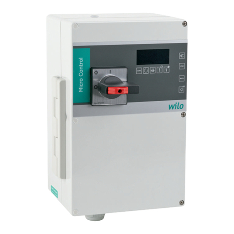
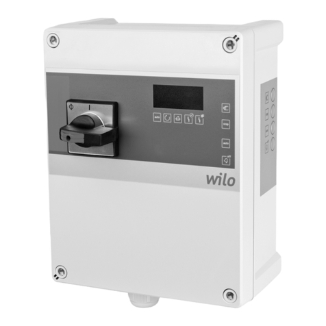
Wilo Control MR-Lift User manual

de Einbau- und Betriebsanleitung
en Installation and operating instructions
fr Notice de montage et de mise en service
es Instrucciones de instalación y funcionamiento
it Istruzioni di montaggio, uso e manutenzione
pt Manual de Instalação e funcionamento
nl Inbouw- en bedieningsvoorschriften
da Monterings- og driftsvejledning
sv Monterings- och skötselanvisning
Asennus- ja käyttöohje
el Οδηγίεςεγκατάστασηςκαιλειτουργίας
hr Upute za ugradnju i uporabu
sr Uputstvo za ugradnju i upotrebu
sl Navodila za vgradnjo in obratovanje
hu Beépítési és üzemeltetési utasítás
pl Instrukcjamontażuiobsługi
cs Návodkmontážiaobsluze
sk Návodnamontážaobsluhu
ru Инструкцияпомонтажуиэксплуатации
ro Instrucţiunidemontajşiexploatare
uk Iнструкціязмонтажутаексплуатації
Wilo-Control MR-Lift
Pioneering for You


5
English
1. Basic Information 6
1.1. General properties 6
1.2. Copyright 6
1.3. Rightsofmodication 6
1.4. Technicalspecication 6
1.5. Control elements 6
2. Assembly and operation 7
2.1. Assembly 7
2.2. Wiring 7
2.3. Level measurement 8
2.4. Test run without pump 8
2.5. Settings 9
2.6. Additional information 10
3. Troubleshooting 11
4. Servicing and maintenance 13
5. Warranty 13
6. Disposal of used equipment 13
Annex - CE declaration of conformity 14

6
English
1. Basic Information
The MR-Lift device is intended to control a
pump’s work, depending on the liquid level. The
maineldsofapplicationinclude:
• Water pumping
• Sewage pumping
• Adjacent sewage pumping stations
• Pressure sewer system
Level can be measured by the use of hydrostat-
icpressure,externalsensor(4–20mA)oroat
switches. The pump is turned on directly by a
contactor.
States of failure are signalled by the use of three
relay contacts, a built-in sound alarm, and a con-
trol light on the front panel. The device is set up
and operated by the use of keys situated on the
front panel.
Thedesignandspecicationofthedevicewill
ensure long and non-failure operation in any
conditions. All the components used in the
construction of the electronic system have been
adjusted to operate in temperatures below zero.
As a result, the possibility of parameters going
out of adjustment, even in freezing temperatures,
has been reduced to a minimum. A high-perfor-
mance switching power supply has been applied
for powering the electronic system, which allows
the minimization of the intake of energy required
for powering the device from the network. The
use of surface assembly technology allowed the
creation of a device of compact construction
which is highly ergonomic in the course of instal-
lation works.
1.1. General properties
•LCDdisplay2x16
• Forced pump operation
• Built-in sound alarm
• Non-potential alarm of high level
•Collectivefailuresignalling:
potential and non-potential
• Overload protection
• Dry run protection
• Phase detection sensor
• Pump’s current indication
• Indication of liquid level in the tank
• Pump’s work-time meter
• Pump’s start up meter
• Saving failure messages after cutting power
supply off
• Wireless communication
1.2. Copyright
This operating and maintenance manual has been
copyrighted by the manufacturer. The operating
and maintenance manual is intended for use by
installation, operating and maintenance person-
nel. It contains technical regulations and drawings
which may not be reproduced or distributed,
either in whole or in part, used for purposes of
competition or shared with third parties. Illustra-
tions may differ from the original and serve only
asanexampleillustrations.
1.3. Rights of modication
The manufacturer reserves the right to make
technicalmodicationstosystemsorcompo-
nents.
1.4. Technical specication
Powerconsumption: 1.8W
Overvoltagecategory: III
Protectionrate: IP 65
Range of work
temperatures: -30°C to +50°C
Rangeofpressure: 0 - 1m of water column
Work voltage
-three-phasework:
-monophasework:
3/N/PE AC 400/230V 50Hz
1/N/PE AC 230V 50Hz
Max. switched power AC-3
-three-phasework:
-monophasework:
5.0kW
2.7kW
Relay contacts
load-carrying capacity
- non-potential
alarmcontacts:
-alarmcontact12VDC:
AC1 - 8A / 230V AC
DC1 - 8A / 24V DC
1.2A
Wireless communication
-standard:
- system transmission
power:
ISM 868MHz
25mW e.r.p.
(ETSIEN300220)
Dimensions: 250x220x118mm
(WxHxD)
Dimensionswithantenna: 265x366x118mm
(WxHxD)
1.5. Control elements
1.5.1. Control keys
“MANUAL OPERATION” Key
Turns on and off the pump regardless of the level
of liquid in the tank, in the case of the setting in
“Workwaterless–allowed”.If“Workwaterless-
disallowed” level must be higher than the STOP
level, otherwise the pump will not start, and the
display shows the message “Manual operation not
allowed”.
Themaximumpossibleoperationtimeinmanual
mode is 2 minutes. After this time, or after a
power failure the unit will return to the previous
mode:“0”or“Automaticoperation”.
“AUTOMATIC OPERATION” Key
The pump is controlled automatically depending
on the level of liquid in the tank and the control
settings. If you press the key again, the pump will
be switched to the “0” mode.

7
English
Navigation key “UP”
Acceptance key
Navigation key “DOWN”
1.5.2. Control lights
Yellow control light – permanently on:
The pump works in either automatic or manual
mode.
Yellow control light – ashing:
Additional pump operation after liquid level in the
tank falls below the switch off level. This time is
set up in the control menu.
Red control light:
Indication of emergency status. Turned on until
the cause for alarm is eliminated.
1.5.3. LCD display
In the normal course of work the upper line of
the display shows the level value or status of
oatswitchcontacts.Ifthepumpisoff,thenthe
down line displays the total time of the pump’s
operation. If the pump is on, then the down line
displays the motor’s current value. If you press
the▲navigationkeyonthedisplayonce,thenit
will display the total number of times the pump
has turned on since it was started.
NOTE!
It is impossible to reset the indications of work-
time and the number of the pump’s starts.
In the case of state of alarm the display will show
appropriate messages, alternating with normal
indications.
2. Assembly and operation
• The device can be assembled and operated only
by a person who possesses appropriate and valid
qualicationsempoweringthemtousedevices,
installationsandnetworksatleastintheeld
of assembly of control-measurement devices,
as well as devices and installations of automatic
adjustment.
• When connecting the device to the wiring
systemorintroducinganymodicationsinthe
connection system, the power supply should be
turned off. Power supply can be turned on after
connecting the wires and replacing the terminal
cover. During operation, employees authorized to
operate the device can have access to connection
terminals only, or else the power supply will be
turned off. Under no circumstances should the
insulationoutsidecover(frontpanel)oftheelec-
tronic and electric part be taken off the device.
2.1. Assembly
The device should be assembled in an upright po-
sition, in a place free from direct contact with rain
or sunlight. Application of an additional protec-
tionboxisuseful.Inplaceswherethetempera-
ture often falls below -20°C it might be necessary
to provide heating.
Thecasingshallbexedtoaverticalbaseusing
three screws or bolts of diameter 4 - 5mm. The
arrangementofxingboltsisshownontheback
wall of the housing. Dependent on the conditions
you may use the catch included in the set. First,
xittotheupperpartofthecasingwithenclosed
screw.Inthiscasethemiddlexingscrewmust
beplaced40mmhigherthanthevaluespecied
on the casing.
The MR-Lift device has no anti-explosion
protection. Therefore, it can be installed only
outside explosion hazard areas.
2.2. Wiring
• The type of current and voltage must be identical
todataspeciedonthedataplateofthedevice.
• Protection on behalf of the network must be
applied(max.16A).
• Ground the pump / device according to regula-
tions.
• Let in endings of wires through relevant cable
glands in the lower part of the casing and connect
them in accordance with markings on the termi-
nal block.
• Unused cable glands must clog.
2.2.1. Delivering power to the control and connecting
pump
Three-phase motor wiring
Single-phase motor wiring

8
English
Therm.1
Switches the pump off after
exceedingthepermissible
temperature value. After
cooling down the pump is
readytowork(chapter3).
Therm.2
Switches the pump off after
exceedingthepermissible
temperature value. The
pump can be restarted after
cooling down the pump and
after the failure has been
accepted(chapter3).
If no thermal protection is
connected to terminals 21,
22, the terminals shall be
bridged.
2.2.2. Control and signal circuit terminals
Connectionterminalsof:
•oatswitches
• thermal protections
•externallevelsensor
NOTE!
All connections must be
made at
non-potential status. De-
livery of external voltage
to any of the connectors
may result in damage to
the controller.
Alarm relay contact termi-
nals:
•terminals1,2–12VDC
potential contacts
•terminals3to6–
non-potential contacts
2.3. Level measurement
MR-Lift is equipped with 2 methods for measur-
ingthelevelofliquidinthetank–linearmeas-
urement(internalsensororexternalpressure
sensor4-20mA)andoatswitches.
2.3.1. Linear level measurement
Measurement of water column pressure in the
range 0 - 100cm.
If the pump is operating in an explosive atmos-
phere, the pump station must be equipped with a
oatindicatinglackofliquid.Removethejumper
from the NLinputandconnecttheoat.Incase
of lack of liquid the display shows “No liquid”, the
alarm will sound and the pump will be stopped.
When using a screw pump the pump station also
mustbeequippedwithaoatindicatinglackof
liquid.
2.3.1.1. Internal sensor
Connectpressurelineofdiameter8x6mmto
the metal connector on the right of the device.
Required pressure can be obtained by use of one
ofthefollowingmethods:
1. Closed cast iron bell hung in the tank.
2. Spargepipemethod:tubeorironbellplacedin
the tank, supplied with bubbles generated by the
membrane pump.
2.3.1.2. External pressure sensor 4-20mA
Externaltwo-wiresensormustbeconnectedto
terminals30(+)i31(-).Thesensorispoweredby
stabilized voltage of 20V.
2.3.2. Float switches
Float inputs work as normally open.
Operation with 2
oatswitches
Operation with 3
oatswitches
Operation with 3
oatswitcheson
a single wire
Choosethe“oats”optionfromthelevelmeas-
urement menu. The display shows the status of all
threecontacts:NL,SW,HL.TheSWoatturnsthe
pump on and off and its hysteresis determines
the difference between the level of turning the
pumponandoff.TheHLoatindicatesahigh
level.TheNLoatindicatesalackofliquid.Ifthe
pumpisoperatinginanexplosiveatmosphere,
thepumpstationmustbeequippedwithaoat
indicating lack of liquid. When using a screw
pump the pump station also must be equipped
withaoatindicatinglackofliquid.
Ifaninappropriatestatusoccurs(e.g.NL=0,
SW=1),thealarmisturnedonandthefollow-
ingmessageisdisplayed:“Floatswitcheswrong
sequence”. Check the status, remove its cause
and accept the alarm. This alarm does not result
in blocking the pump’s start and the pump will
workdespitefailuresofoatswitches.TheHL
oatturnsthepumponimmediately,regardless
ofoatsSW. It must be noted that the high level
oatswitchterminalisalwaysactive,evenif
another method of level measurement has been
chosen from the menu.
2.4. Test run without pump
To check working of the control system with no
pump connected, proceed in accordance with the
followinginstructions:
1. Turnthepowersupplyon(itisenoughtoconnect
L1,N,PE).
2. Fromthemenuset“Maximumcurrent”to0.0A.
Otherwise an alarm will occur and the message
“No load” will be displayed.
3. From the menu turn off the “Therm.protect1”.
Otherwise an alarm will occur and the message
“Thermal fault 1” will be displayed.
4. Close terminals 21, 22. Otherwise an alarm will
occur and the message “Thermal fault 2” will
occur.

9
English
2.5. Settings
Todisplaymenuoptionsusenavigationkeys▲
and▼accordingtothefollowingscheme:
•Mainscreen-▲-Pump’sstartupmeter-▲-
Firstmenulevel-▲-Subsequentkeypressmenu
scrolling levels from 1 upwards.
•Mainscreen-▼-Lastmenulevel-▼-Subse-
quent key press menu scrolling levels from the
last level down.
If no key is pressed, then after 8 seconds the
menu will be closed.
The upper line of the each display shows the
name of the option, while the lower line shows
itssettingswhichcanbemodied.Inorderto
change a settings press “OK”. The current name
oftheoptionwillstarttoash.Thisallowstoset
upparameterswithnavigationkeys▲and▼.If
you hold one of the keys pressed for longer, the
value being set will change more rapidly. If you
press the key “OK” again, the new value will be
saved.
The table below displays all the menu options
alongwithexplanations.
Upper line of
display
Range of
settings
Explanation
Level measurm. internal
sensor
Liquid level measured with
hydrostatic pressure or
sparge pipe.
4-20
sensor
1.0m
Liquid level measured with
externalsensor
(0-1mrange).
4-20
sensor
2.0m
Liquid level measured with
externalsensor
(0-2mrange).
4-20
sensor
2.5m
Liquid level measured with
externalsensor
(0-2.5mrange).
4-20
sensor
4.0m
Liquid level measured with
externalsensor
(0-4mrange).
oat
switches
Liquid level measured with
oatswitches.
STOP level 0 - 91 cm Level at which the pump
turns off.
Readiness level 3 - 94 cm Level sent to the central
unit.
START level 6 - 97 cm Level at which the pump
turns on in case of no radio
communication, after
exceedingthetimeofno
communication.
High level 9 - 100 cm When the set level value is
exceededrelaycontactsof
the collective failure report
system and high level relay
are switched on.
Minimum
current
0 - 12 A When the pump’s current
falls below the set value,
the message “Dry run” will
be displayed, and after the
expirationofadjustedtime
(“Dryruntime”),thedevice
will turn the pump off and
report a failure. The pump
can be turned on again
after the failure is deleted
with the “OK” key. Current
of the pump decrease if
there is no liquid in the
tank or if the delivery pipe-
line is clogged.
Maximum
current
0 - 12 A If the pump’s current
exceedsthesetvalue,the
message “Overcurrent” will
be displayed. If this state
remains unchanged for a
speciedperiodoftime,
the device turns the pump
off and reports a failure.
The pump can be started
again after acceptance is
made with the “OK” key.
Dry run time 5 - 180 s Indicates how long the
pump is going to work
after the pump’s current
falls below the set value
of “Minimum current”.
After this period of time
there will be a break in the
pump’s work, or it will be
stopped in failure mode.
Pause time 5 - 15 min The time of the break in
the pump’s work after it is
stopped as a result of a dry
run. The time remaining till
the end of the break will be
displayed. No break occurs
if the value of the setting
“Dry run cycles”
is 1.
Dry run cycles 1 - 5 Number of work cycles
at the dry run state, after
which the pump is stopped
and the failure is reported.
Start delay 0 - 240 s Delay of pump’s start up
after the power supply
voltagedecays–thepump
can be turned on after a
speciedperiodoftime.
The display shows the
time, which remains to
the pump’s start up. This
setting is to prevent pumps
inunitssituatednextto
each other from simultane-
ous startup after decay of
voltage.

10
English
Additional
work
0 - 120 s After the liquid level falls
below the set value “STOP
Level”, the pump will work
for a period of time speci-
edhere.
Wait time
comm.
1 - 30 min No communication time.
Time after which the
device enters automatic
operation when no com-
munication is present.
24h-5s work enabled After 24 hours standby
the pump is automatically
turned on for 5 seconds in
order to lubricate bearings.
disabled
Sound alarm enabled Failure is reported by an
internal sound signalling
device.
disabled
Pulsing alarm enabled The failure report relay is
turned on every second. It
can be used for supplying
powertoanexternalsignal
lamp.
disabled In the case of failure the
relay is switched on perma-
nently.
Therm.protect1 enabled Set to “disabled” if thermal
protection contacts have
not been connected to
terminals 20, 21.
disabled
Work waterless allowed The pump can be start-
ed even if the liquid level
in the tank is below the
value at which the pump is
turned off.
disallowed The pump cannot be start-
ed if the liquid level in the
tank is below the value at
which the pump is turned
off. This parameter should
be set in case of hazard of
explosion.
Phase control enabled The phase monitoring
system protects the pump
against non-uniform volt-
age or incorrect order of
phases, and detects con-
tactor failure. In the case of
a single-phase pump, set
to “disabled”.
disabled
Language polish, english, german, czech
2.6. Additional information
2.6.1. Setting level values
The MR-Lift prevents the setting of unacceptable
levels values, e.g. the value of the level at which
the pump is turned off higher than the respec-
tive level of turning it on. Minimum difference
between level settings is 3 cm.
2.6.2. Setting current values
The MR-Lift prevents the setting of unacceptable
current values, e.g. minimum current value higher
thanmaximumcurrentvalue.
2.6.3. LCD contrast setting
The default contrast setting is optimum, and
there is usually no need to change it. However,
if such a necessity occurs, the following action
shouldbetaken:
1. Turn off the device.
2. Press and hold the keys “MANUAL OPERATION”
and “AUTOMATIC OPERATION” at the same time.
3. Turnonthedevice–themessage“Contrast”will
be displayed.
4. Set required value with navigation keys.
5. Release the pressed keys “MANUAL OPERATION”
and “AUTOMATIC OPERATION”.
2.6.4. Calibration of internal level sensor
After long use the indications of the internal level
sensor may stop being accurate. In such a case,
even if there is no pressure, indication of level
may be other than zero. In order to calibrate the
sensorproceedasfollows:
1. Turn off the device.
2. Press and hold the keys “MANUAL OPERATION”
and “AUTOMATIC OPERATION” at the same time.
3. Turnonthedevice–themessage“Contrast”will
be displayed.
4. Press the acceptance key “OK” - the message
“Internal sensor calibrated” will be displayed.
5. Release the pressed keys “MANUAL OPERATION”
and “AUTOMATIC OPERATION”.
It is recommended to calibrate the sensor at each
technical review.
NOTE!
Before you start to calibrate the level sensor,
raise the bell over the water surface.
2.6.5. Settings lock
To avoid making changes to the settings by unau-
thorized persons, the MR-Lift is equipped with a
lock function.
If the settings lock is on, when you try to change
settings, the display shows the message “Settings
locked”.
To activate the settings lock, press and hold the
“OK” key and press “MANUAL OPERATION”
key(thedisplayshowsthemessage„Settings
locked”).Todisablethelockmustrepeatthe
aboveprocedure(thedisplayshowsthemessage
„Settingsunlocked”).
Locking and unlocking can be activated only in
the home screen mode.
2.6.6. Wireless communication
MR-Lift operation is controlled by means of a
radio communication system in ISM 868MHz
standard. The system consists of controlling soft-
11
English
ware, a gate and MR-Lift devices. The controlling
software can be operated from any computer
connected to the Internet.
If there is no signal between MR-Lft and the
central unit, MR-Lift enters automatic operation
mode independent from the wireless system and
the following recurring message appears on the
display:“Noradiocommunication”.Thetimedu-
ration after which the device enters the automat-
ic operation mode can be set in the menu.
If the MR-Lift device is locked by the system
administrator, the message “Blocked by
administrator”ashesonthedisplay.Unlocking
can only be done by radio. During the lock, the
pump can not be started from the panel.
NOTE!
The sim card used in the gateway must be
congured in such a way that no PIN code is
required. In order to congure the sim card cor-
rectly, please insert it into a mobile phone, go
to security settings in the mobile phone menu
and disable prompting for PIN code. The card is
now ready to be inserted into the gateway.
3. Troubleshooting
Displayed
message
Additional
information
Cause Solution
High level • Signal of
failure
• High level
relay turned
on
• Automatic
deletion of
the state of
failure after
the liquid
level falls
Level of
liquid in
the tank
exceeded
value set in
menu.
Check if the
device works
in automatic
mode or if
the pump is
not turned
off as a
result of over
temperature,
overcurrent
or a dry
run. After
all, check if
the delivery
pipeline is
clogged.
Float switch
High level
• Signal of
failure
• High level
relay turned
on
• Automatic
deletion of
the state of
failure after
the liquid
level falls
Level of
liquid in the
tank caused
switching
on the high
leveloat.
Iftheoat
switch
has been
connected
as additional
protection to
the standard
control sys-
tem, check if
the message
“High level”
is displayed
at the same
time. If
not, check
how high
theoat
is hung in
the tank. In
other cases
proceed as in
the case of
“High level”
status.
Float
switches
Wrong se-
quence
• Signal of
failure
• State of
failure saved
Float
switches
work in
the wrong
sequence.
Checkoat
connection,
then check
how high
they are
hung in the
tank and if
they are tan-
gled. Check
if they are
not dam-
aged and if
they switch
on correctly.
Delete fail-
ure with the
“OK” key.
Sensor
4-20mA
disconnect-
ed
• Signal of
failure
• Automatic
deletion of
the state of
failure after
the sensor is
connected
External
sensor cur-
rent is lower
than 3mA.
Checkex-
ternal sensor
and its
connecting
wire.
Overcurrent • A message
displayed
• The pump
works
Pump cur-
rent is higher
than the
value set for
“Maximum
current”.
Turn off the
pump, check
the value of
“Maximum
current” and
look for the
cause of the
overcurrent.

12
English
Overcurrent • Signal of
failure
• The pump
is stopped
• State of
failure saved
The value of
“Maximum
current”
has been
exceededfor
a long time
and resulted
in turning
the pump
off.
After the
cause is
removed,
press the
“OK” key.
The pump
is ready to
work again.
No load • Signal of
failure
• The pump
is stopped
• State of
failure saved
Pump dis-
connected.
After the
cause is
removed,
press the
“OK” key.
The pump
is ready to
work again.
Dry run • A message
displayed
• The pump
works
Pump cur-
rent is lower
than the
value set for
“Minimum
current”. It
means that
the pump
is working
with no
liquid or that
the delivery
pipeline is
clogged.
Check the
value of the
“Minimum
current” set-
ting. Check
the level in
the tank.
Check if
the delivery
pipeline is
clogged.
Dry run • Signal of
failure
• The pump
is stopped
• State fail-
ure saved
Pump’s
work-time
in the last
dry duty
cycle, at too
low current
exceeded
value set for
the “Dry run
time” and
the pump
has been
turned off.
After the
cause is
removed,
press the
“OK” key.
The pump
is ready to
work again.
No liquid • Signal of
failure
• The pump
is stopped
Dryrunoat
switch is
open.
Check the
liquid level
in the tank.
Check the
oatswitch-
es.
After the
cause is
removed
the pump
is ready to
work again.
Thermal
fault 1
• Signal of
failure
• The pump
is stopped
• After the
fault is
removed
the state
of failure is
deleted au-
tomatically
Acceptable
temperature
for the pump
has been
exceeded
–contacts
of thermal
protection
connected
to terminals
20, 21 are
open.
Find and
remove the
cause.
If no thermal
protection is
connected
to terminals
20, 21, from
the menu
switch off
“Therm.
protect1”.
NOTE!
After the
pump is
cooled
down, the
fault is au-
tomatically
reset and
the pump
is ready to
work again.
Thermal
fault 2
• Signal of
failure
• The pump
is stopped
• State fail-
ure saved
Acceptable
temperature
for the pump
has been
exceeded
–contacts
of thermal
protection
connected
to terminals
21, 22 are
open.
After the
cause is
removed and
the pump
is cooled
down, press
the “OK”
key. The
pump is
ready to
work again.
Low voltage
L1
• Signal of
failure
• The pump
is stopped
Voltage in
phase L1
falls below
190V.
After the
cause is
gone, the
pump is
ready to
work.
Low voltage
L2
• Signal of
failure
• The pump
is stopped
Voltage in
phase L2
falls below
190V.
After the
cause is
gone, the
pump is
ready to
work.
Low voltage
L3
• Signal of
failure
• The pump
is stopped
Voltage in
phase L3
falls below
190V.
After the
cause is
gone, the
pump is
ready to
work.
Low voltage
L1, L2
• Signal of
failure
• The pump
is stopped
Voltage in
phases L1
and L2 falls
below 190V.
After the
cause is
gone, the
pump is
ready to
work.

13
English
Low voltage
L2, L3
• Signal of
failure
• The pump
is stopped
Voltage in
phases L2
and L3 falls
below 190V.
After the
cause is
gone, the
pump is
ready to
work.
Low voltage
L1, L3
• Signal of
failure
• The pump
is stopped
Voltage in
phases L1
and L3 falls
below 190V.
After the
cause is
gone, the
pump is
ready to
work.
Low voltage
L1, L2, L3
• Signal of
failure
• The pump
is stopped
Voltage in all
phases falls
below 190V.
After the
cause is
gone, the
pump is
ready to
work.
3 phases
wrong se-
quence
• Signal of
failure
• The pump
is stopped
Wrong se-
quence of all
phases.
Swap supply
lines.
Contactor
fault
• Signal of
failure
• The pump
is stopped
Failure of
one or more
contacts of
the contac-
tor.
Have the
failure
removed in
service.
No radio
communica-
tion
• No signal
of radio
communica-
tion
• The device
operates
automatical-
ly inde-
pendently
from the
wireless
system
No queries
from the
central unit
or no radio
range.
Check the
operation
of the Wilo
Pressure
Control.
Check inter-
net gateway
communica-
tion.
No SPI
communica-
tion
• No signal
of SPI com-
munication
• The device
operates
automatical-
ly inde-
pendently
from the
wireless
system
Failure of the
radio com-
munication
module.
Deliver the
device to
the service
center.
If you press the “OK” key in a state of failure,
the sound alarm will be turned off and the relay
contacts of the collective alarm system will
return to their normal state. The failure will be
completely deleted after its causes are removed
and the “OK” key is pressed once again.
4. Servicing and maintenance
In order to protect the device from moisture
and dust keep the door and the terminal cover
closed. Cable glands should be tightly screwed.
Unused cable glands must clog.
It is recommended that the following checks at
intervalsof6-month:
1. Check the state of electrical connections and, if
necessary, tight connection terminals.
2. Check the state and sealing of the pressure line.
3. If a sparge pipe compressor is used, check visually
how it works.
4. Check the state of the bell in the tank and clean it
if necessary.
5. Check indication of zero level at emerged bell. If it
is different from zero, check carefully that the bell
is not clogged and calibrate in accordance with
the description included in chapter 2.6.4.
6. Iftheoatswitchesareapplied,checkthatthey
are clean and not tangled.
7. If you are used the 4-20mA level sensor, make
sure it is not too much polluted, which can cause
incorrect measurement.
5. Warranty
The MR-Lift device is covered under warranty for
a period of 24 months. During that period any
hidden faults and defects due to the manufactur-
er’sfaultshallberectiedfreeofcharge.
Thewarrantydoesnotcover:
1. Mechanical damage
2. Damage due to repairs carried out by unauthor-
ized persons.
3. Damage due to power line overvoltage.
4. Damage caused by failure to tightness of the
device.
Any traces of interference, seal or mechanical
damage that may cause moisture and other
impurities to enter the interior of the device shall
result in the warranty becoming void.
6. Disposal of used equipment
This symbol on the package of a product means
that the product must not be disposed of along
with other communal waste. The user is responsi-
ble for the delivery of the used device to a spec-
iedplacewhereusedelectricalandelectronic
devices are collected. Separate collection and
recycling of this sort of waste plays a major role in
natural resource protection and safety for health,
and the natural environment. Further information
on the disposal of used devices can be obtained
from appropriate local authorities, in companies
responsible for waste disposal, or at the place of
purchase.

EN 60730–1:2016; EN 60730–2–15:2010; EN 61000–6–2:2005; EN 61000–6–3:2007+A1:2011;
EN 300 220–1 V3.1.1; EN 300 220–2 V3.1.1; EN IEC 63000:2018;
WILO SE
Group Quality
Wilopark 1
D-44263 Dortmund
Person authorized to compile the technical file is:
Bevollmächtigter für die Zusammenstellung der technischen Unterlagen ist:
in their delivered state comply with the following relevant directives and with the relevant national legislation:
in der gelieferten Ausführung folgenden einschlägigen Bestimmungen entsprechen 'und entsprechender
nationaler Gesetzgebung:
Dortmund,
F_GQ_013-72 ORIGINAL DECLARATION / ORIGINAL-ERKLÄRUNG
H. HERCHENHEIN
Senior Vice President - Group Quality & Qualification
Declaration n°2215811-rev01
PC As-Sh n°2216680-EU-rev01
Wilopark 1
D-44263 Dortmund
DECLARATION OF CONFORMITY
KONFORMITÄTSERKLÄRUNG
We, the manufacturer, declare under our sole
responsibility that these electronic control panel types
of the series,
Als Hersteller erklären wir unter unserer alleinigen
Verantwortung, dass die elektronischen Schaltgeräte
der Baureihen,
W-CTRL-MR-L-…
(The serial number is marked on the product site plate)
(Die Seriennummer ist auf dem Typenschild des Produktes angegeben)
_ 2014/35/EU - LOW VOLTAGE / NIEDERSPANNUNGSRICHTLINIE
_ 2014/30/EU - ELECTROMAGNETIC COMPATIBILITY / ELEKTROMAGNETISCHE VERTRÄGLICHKEIT - RICHTLINIE
_ 2014/53/EU - RADIO EQUIPMENT - DIRECTIVE / FUNKANLAGEN - RICHTLINIE
_ 2011/65/EU + 2015/863 - RESTRICTION OF THE USE OF CERTAIN HAZARDOUS SUBSTANCES /
BESCHRÄNKUNG DER VERWENDUNG BESTIMMTER GEFÄHRLICHER STOFFE-RICHTLINIE
comply also with the following relevant standards:
sowie auch den Bestimmungen zu folgenden harmonisierten europäischen Normen:

EL
ES
FR
IT
PT
Declaration n°2215811-rev01 PC As-Sh n°2216680-EU-rev01
Tradução oficial da
Declaração
|| 2014/35/EU - Baixa Voltagem || 2014/30/EU - Compatibilidade Electromagnética || 2014/53/EU - Equipamentos de
rádio || 2011/65/EU + 2015/863 - relativa à restrição do uso de determinadas substâncias perigosas
EN 60730–1:2016; EN 60730–2–15:2010; EN 61000–6–2:2005; EN 61000–6–3:2007+A1:2011;
EN 300 220–1 V3.1.1; EN 300 220–2 V3.1.1; EN IEC 63000:2018;
Pessoa autorizada para a elaboração de documentos técnicos:
Nós, o fabricante, declaramos sob nossa exclusiva responsabilidade que
o(s) quadro(s) de controlo eletrónico da(s) série(s), W-CTRL-MR-L-…(O nº de série está marcado na placa de características do produto)
está em conformidade com a versão fornecida nas se
g
uintes dis
p
osi
ç
ões
relevantes e de acordo com a legislação nacional
assim como as seguintes disposições das normas europeias
WILO SE
Group Quality
Wilopark 1
D-44263 Dortmund
Traduzione ufficiale della
Dichiarazione
|| 2014/35/EU - Bassa Tensione || 2014/30/EU - Compatibilità Elettromagnetica || 2014/53/EU - Apparecchiature radio ||
2011/65/EU + 2015/863 - sulla restrizione dell’uso di determinate sostanze pericolose
EN 60730–1:2016; EN 60730–2–15:2010; EN 61000–6–2:2005; EN 61000–6–3:2007+A1:2011;
EN 300 220–1 V3.1.1; EN 300 220–2 V3.1.1; EN IEC 63000:2018;
La persona autorizzata a compilare il fascicolo tecnico è:
Noi, il costruttore, dichiariamo sotto la nostra esclusiva responsabilità che
questi tipi di quadri elettronici della serie, W-CTRL-MR-L-…(Il numero di serie è riportato sulla targhetta del sito del prodotto)
allo stato di conse
g
na sono conformi alle se
g
uenti direttive
p
ertinenti e alla
legislazione nazionale pertinente:
rispettare anche le seguenti norme pertinenti:
WILO SE
Group Quality
Wilopark 1
D-44263 Dortmund
Traduction officielle de la
déclaration
|| 2014/35/EU - BASSE TENSION || 2014/30/EU - COMPATIBILITE ELECTROMAGNETIQUE || 2014/53/EU - EQUIPEMENTS
RADIOELECTRIQUES || 2011/65/EU + 2015/863 - LIMITATION DE L'UTILISATION DE CERTAINES SUBSTANCES
DANGEREUSES
EN 60730–1:2016; EN 60730–2–15:2010; EN 61000–6–2:2005; EN 61000–6–3:2007+A1:2011;
EN 300 220–1 V3.1.1; EN 300 220–2 V3.1.1; EN IEC 63000:2018;
Personne autorisée à constituer le dossier technique est :
Nous, fabricant, déclarons sous notre seule responsabilité que les types de
coffrets électroniques des séries, W-CTRL-MR-L-…Le numéro de série est inscrit sur la plaque signalétique du produit)
dans leur état de livraison sont conformes aux dis
p
ositions des directives
suivantes et aux législations nationales les transposant :
sont également conformes aux dispositions des normes européennes harmonisées suivantes :
WILO SE
Group Quality
Wilopark 1
D-44263 Dortmund
Traducción oficial de la
Declaración
|| 2014/35/EU - Baja Tensión || 2014/30/EU - Compatibilidad Electromagnética || 2014/53/EU - Equipos radioeléctricos ||
2011/65/EU + 2015/863 - Restricciones a la utilización de determinadas sustancias peligrosas
EN 60730–1:2016; EN 60730–2–15:2010; EN 61000–6–2:2005; EN 61000–6–3:2007+A1:2011;
EN 300 220–1 V3.1.1; EN 300 220–2 V3.1.1; EN IEC 63000:2018;
Persona autorizada para la recopilación de los documentos técnicos:
Nosotros, el fabricante, declaramos bajo nuestra exclusiva responsabilidad
que los cuadros de control electrónicos de la(s) serie(s) W-CTRL-MR-L-…(El nº de serie está marcado en la placa de características del producto)
cum
p
le en la e
j
ecución suministrada las si
g
uientes dis
p
osiciones
pertinentes y la legislación nacional correspondiente:
así como las disposiciones de las siguientes normas europeas armonizadas:
WILO SE
Group Quality
Wilopark 1
D-44263 Dortmund
Επίσημη μετάφραση της
Διακήρυξης
|| 2014/35/EU - Χαμηλής Tάσης || 2014/30/EU - Ηλεκτρομαγνητικής συμβατότητας || 2014/53/EU - Ραδιοεξοπλισμού ||
2011/65/EU + 2015/863 - για τον περιορισμό της χρήσης ορισμένων επικίνδυνων ουσιών
EN 60730–1:2016; EN 60730–2–15:2010; EN 61000–6–2:2005; EN 61000–6–3:2007+A1:2011;
EN 300 220–1 V3.1.1; EN 300 220–2 V3.1.1; EN IEC 63000:2018;
Πρόσωπο εξουσιοδοτημένο να συντάξει το τεχνικό αρχείο είναι:
W-CTRL-MR-L-…
Εμείς, οκατασκευαστής, δηλώνουμε με αποκλειστικά δική μας ευθύνη ότι
αυτοί οι τύποι ηλεκτρονικών πινάκων ελέγχου της σειράς,
(Οσειριακός αριθμός σημειώνεται στo ταμπελάκι του προϊόντος)
στ
η
νκατάστασ
η
πα
ρ
άδοσ
ης
συ
μμ
ο
ρφ
ώνονται
μ
ετι
ς
ακόλουθε
ς
σ
χ
ετικέ
ς
οδηγίες και τη σχετική εθνική νομοθεσία:
συμμορφώνεται επίσης με εναρμονισμένα πρότυπα:
WILO SE
Group Quality
Wilopark 1
D-44263 Dortmund

DA
ET
FI
IS
LT
Declaration n°2215811-rev01 PC As-Sh n°2216680-EU-rev01
EN 60730–1:2016; EN 60730–2–15:2010; EN 61000–6–2:2005; EN 61000–6–3:2007+A1:2011;
EN 300 220–1 V3.1.1; EN 300 220–2 V3.1.1; EN IEC 63000:2018;
Sá sem hefur heimild til að taka saman tækniskrána er:
Oficialus deklaracijos
vertimas
|| 2014/35/EU - Žema įtampa || 2014/30/EU - Elektromagnetinis Suderinamumas || 2014/53/EU - Radijo įranga ||
2011/65/EU + 2015/863 - dėl tam tikrųpavojingųmedžiagųnaudojimo apribojimo
Opinber þýðing á
yfirlýsingunni
|| 2014/35/EU - Lágspennutilskipun || 2014/30/EU - Rafseguls-samhæfni-tilskipun || 2014/53/EU - Útvarpstæki ||
2011/65/EU + 2015/863 - Takmörkun á notkun tiltekinna hættulegra efna
EN 60730–1:2016; EN 60730–2–15:2010; EN 61000–6–2:2005; EN 61000–6–3:2007+A1:2011;
EN 300 220–1 V3.1.1; EN 300 220–2 V3.1.1; EN IEC 63000:2018;
Asmuo įgaliotas sudaryti techninius dokumentus yra:
taip pat atitinka sekančius aktualius standartus:
WILO SE
Group Quality
Wilopark 1
D-44263 Dortmund
Við framleiðandinn lýsum því yfir undir okkar ábyrgð að þessar rafrænu
stjórnborðsgerðir seríunnar, W-CTRL-MR-L-…(Raðnúmerið er merkt á plötunni á vörustaðnum)
í afhentu ástandi í samræmi við eftirfarandi viðei
g
andi tilski
p
anir o
g
viðeigandi innlenda löggjöf:
Mes, kaip gamintojas, savo atsakomybės ribose deklaruojame, kad šios
serijos automatikos valdymo spintųmodeliai, W-CTRL-MR-L-…(Serijos numeris pažymėtas ant produkto lentelės)
tai
p
kai
p
p
ristat
y
ti, atitinka sekančias aktualias direkt
y
vas ir nacionalines
teisės normas bei reglamentus:
Julistuksen virallinen
käännös
|| 2014/35/EU - Matala Jännite || 2014/30/EU - Sähkömagneettinen Yhteensopivuus || 2014/53/EU - Radiolaitteet ||
2011/65/EU + 2015/863 - tiettyjen vaarallisten aineiden käytön rajoittamisesta
EN 60730–1:2016; EN 60730–2–15:2010; EN 61000–6–2:2005; EN 61000–6–3:2007+A1:2011;
EN 300 220–1 V3.1.1; EN 300 220–2 V3.1.1; EN IEC 63000:2018;
Henkilö, jolla on valtuudet koota tekninen tiedosto, on:
noudattamaan myös seuraavia asiaankuuluvia standardeja:
WILO SE
Group Quality
Wilopark 1
D-44263 Dortmund
uppfylla einnig eftirfarandi viðeigandi staðla:
WILO SE
Group Quality
Wilopark 1
D-44263 Dortmund
Valmistaja vakuuttaa yksinomaisella vastuullaan, että nämä sarjan
elektroniset ohjauspaneelit, W-CTRL-MR-L-…(Sarjanumero on merkitty tuotekohtaiseen kilpeen)
toimitetussa tilassa noudattavat seuraavia asiaankuuluvia direktiive
j
ä
j
a
asiaa koskevaa kansallista lainsäädäntöä:
Deklaratsiooni ametlik
tõlge
|| 2014/35/EU - Madalpingeseadmed || 2014/30/EU - Elektromagnetilist Ühilduvust || 2014/53/EU - Raadioseadmete ||
2011/65/EU + 2015/863 - teatavate ohtlike ainete kasutamise piiramise kohta
EN 60730–1:2016; EN 60730–2–15:2010; EN 61000–6–2:2005; EN 61000–6–3:2007+A1:2011;
EN 300 220–1 V3.1.1; EN 300 220–2 V3.1.1; EN IEC 63000:2018;
Tehnilise toimiku koostamiseks on volitatud isik:
vastama ka järgmistele asjakohastele standarditele:
WILO SE
Group Quality
Wilopark 1
D-44263 Dortmund
Meie, tootja, kuulutame ainuisikulisel vastutusel, et need seeria
elektroonilised juhtpaneelid, W-CTRL-MR-L-…(Seerianumber on märgitud toote saidi plaadile)
oma tarnitud olekus
j
är
g
ima
j
är
g
misi as
j
akohaseid direktiive
j
a
asjakohaseid siseriiklikke õigusakte:
Officiel oversættelse af
erklæringen
|| 2014/35/EU - Lavspændings || 2014/30/EU - Elektromagnetisk Kompatibilitet || 2014/53/EU - Radioudstyr ||
2011/65/EU + 2015/863 - Begrænsning af anvendelsen af visse farlige stoffer
EN 60730–1:2016; EN 60730–2–15:2010; EN 61000–6–2:2005; EN 61000–6–3:2007+A1:2011;
EN 300 220–1 V3.1.1; EN 300 220–2 V3.1.1; EN IEC 63000:2018;
Person, der er autoriseret til at udarbejde den tekniske fil, er:
Vi, producenten, erklærer under vores eget ansvar, at disse typer
elektroniske betjeningspaneler i serien, W-CTRL-MR-L-…(Serienummeret er markeret på produktpladen)
i deres leverede tilstand overholde føl
g
ende relevante direktiver o
g
den
relevante nationale lovgivning:
også overholde følgende relevante standarder:
WILO SE
Group Quality
Wilopark 1
D-44263 Dortmund

LV
NL
NO
SV
GA
Declaration n°2215811-rev01 PC As-Sh n°2216680-EU-rev01
Eadar-theangachadh
oifigeil den Ghairm
|| 2014/35/EU - Ísealvoltais || 2014/30/EU - Comhoiriúnacht Leictreamaighnéadach || 2014/53/EU - Trealamh raidió ||
2011/65/EU + 2015/863 - Srian ar an úsáid a bhaint as substaintí guaiseacha acu
EN 60730–1:2016; EN 60730–2–15:2010; EN 61000–6–2:2005; EN 61000–6–3:2007+A1:2011;
EN 300 220–1 V3.1.1; EN 300 220–2 V3.1.1; EN IEC 63000:2018;
Is e an neach le ùghdarras am faidhle teicnigeach a chur ri chèile:
Bidh sinn, an neach-dèanamh, a ’foillseachadh fon aon uallach againn gu
bheil na seòrsachan pannal smachd dealanach sin den t-sreath, W-CTRL-MR-L-…(Tha an àireamh sreathach air a chomharrachadh air clàr làrach an toraidh)
anns an stàit lìbhri
g
idh aca
g
èilleadh ris na stiùiridhean buntainneach a
leanas agus ris an reachdas nàiseanta buntainneach:
gèilleadh cuideachd ris na h-inbhean iomchaidh a leanas:
WILO SE
Group Quality
Wilopark 1
D-44263 Dortmund
Officiell översättning av
försäkran
|| 2014/35/EU - Lågspännings || 2014/30/EU - Elektromagnetisk Kompatibilitet || 2014/53/EU - Radioutrustning ||
2011/65/EU + 2015/863 - begränsning av användning av vissa farliga ämnen
EN 60730–1:2016; EN 60730–2–15:2010; EN 61000–6–2:2005; EN 61000–6–3:2007+A1:2011;
EN 300 220–1 V3.1.1; EN 300 220–2 V3.1.1; EN IEC 63000:2018;
Person behörig att sammanställa denna tekniska fil är:
Vi, tillverkaren, försäkrar under eget ansvar att elektroniska styrpanelerna
i serien W-CTRL-MR-L-…(Serienumret finns utmärkt på produktens dataskylt)
i det utförande de levererades överrenstämmer med föl
j
ande relevanta
direktiv och relevant nationell lagstiftning
överrenstämmer också med följande relevanta standarder:
WILO SE
Group Quality
Wilopark 1
D-44263 Dortmund
Offisiell oversettelse av
erklæring
|| 2014/35/EU - Lavspenningsdirektiv || 2014/30/EU - EMV–Elektromagnetisk kompatibilitet || 2014/53/EU - Direktiv
radioutstyr og teleterminalutstyr || 2011/65/EU + 2015/863 - Begrensning av bruk av visse farlige stoffer
EN 60730–1:2016; EN 60730–2–15:2010; EN 61000–6–2:2005; EN 61000–6–3:2007+A1:2011;
EN 300 220–1 V3.1.1; EN 300 220–2 V3.1.1; EN IEC 63000:2018;
Vedkommendesom er autorisert til å sammenstille teknisk fil er:
Vi som produsent erklærer herved vårt ansvar at automatikkstyreskap
under type serie, W-CTRL-MR-L-…(serienummeret er markert på pumpeskilt )
I levert tilstand vil
p
rodukt overholde føl
g
ende direktiver o
g
relevant
nasjonal lovgivning
Oppfølger også relevante standarder
WILO SE
Group Quality
Wilopark 1
D-44263 Dortmund
Officiële vertaling van de
verklaring
|| 2014/35/EU - Laagspannings || 2014/30/EU - Elektromagnetische Compatibiliteit || 2014/53/EU - Radioapparatuur ||
2011/65/EU + 2015/863 - betreffende beperking van het gebruik van bepaalde gevaarlijke stoffen
EN 60730–1:2016; EN 60730–2–15:2010; EN 61000–6–2:2005; EN 61000–6–3:2007+A1:2011;
EN 300 220–1 V3.1.1; EN 300 220–2 V3.1.1; EN IEC 63000:2018;
De persoon die bevoegd is om het technische bestand samen te stellen is:
Als fabrikant verklaren wij onder onze eigen verantwoordelijkheid dat de
elektronische schakelapparatuur van de serie, W-CTRL-MR-L-…(Het serienummer staat vermeld op het naamplaatje van het product)
in de
g
eleverde versie voldoen aan de vol
g
ende relevante be
p
alin
g
en en
aan de overeenkomstige nationale wetgeving:
voldoen ook aan de volgende relevante normen:
WILO SE
Group Quality
Wilopark 1
D-44263 Dortmund
Deklarācijas oficiālais
tulkojums
|| 2014/35/EU - Zemsprieguma || 2014/30/EU - Elektromagnētiskās Saderības || 2014/53/EU - Radioiekārtas ||
2011/65/EU + 2015/863 - par dažu bīstamu vielu izmantošanas ierobežošanu 2011/65/UE
EN 60730–1:2016; EN 60730–2–15:2010; EN 61000–6–2:2005; EN 61000–6–3:2007+A1:2011;
EN 300 220–1 V3.1.1; EN 300 220–2 V3.1.1; EN IEC 63000:2018;
Persona pilnvarota sastādīt tehnisko dokumentāciju:
Mēs, ražotājs, ar pilnu atbildību paziņojam, ka šo sēriju vadības automātika
W-CTRL-MR-L-…(Sērijas numurs ir norādīts uz izstrādājuma plāksnītes)
p
ie
g
ādātā
j
a valstīatbilst šādām attiecī
g
ām direktīvām un attiecī
g
iem valsts
tiesību aktiem:
atbilst arīsekojošiem attiecīgiem standartiem:
WILO SE
Group Quality
Wilopark 1
D-44263 Dortmund

BG
CS
HR
HU
PL
Declaration n°2215811-rev01 PC As-Sh n°2216680-EU-rev01
EN 60730–1:2016; EN 60730–2–15:2010; EN 61000–6–2:2005; EN 61000–6–3:2007+A1:2011;
EN 300 220–1 V3.1.1; EN 300 220–2 V3.1.1; EN IEC 63000:2018;
A
műszaki
dokumentáció
összeállítására
jogosult
személy:
Oficjalne tłumaczenie
Deklaracji Zgodności
|| 2014/35/EU - Niskich Napięć || 2014/30/EU - Kompatybilności Elektromagnetycznej || 2014/53/EU - Urządzeńradiowe
|| 2011/65/EU + 2015/863 - sprawie ograniczenia stosowania niektórych niebezpiecznych substancji
A
N
y
il
a
tk
oza
t
hi
va
t
a
l
os
fordítása
|| 2014/35/EU - Alacsony Feszültségű|| 2014/30/EU - Elektromágneses összeférhetőségre || 2014/53/EU -
Rádióberendezések || 2011/65/EU + 2015/863 - egyes veszélyes való alkalmazásának korlátozásáról
EN 60730–1:2016; EN 60730–2–15:2010; EN 61000–6–2:2005; EN 61000–6–3:2007+A1:2011;
EN 300 220–1 V3.1.1; EN 300 220–2 V3.1.1; EN IEC 63000:2018;
Osoba upoważniona do sporządzenia dokumentacji technicznej:
sąrównieżzgodne z następującymi specyfikacjami technicznymi mającymi zastosowanie:
WILO SE
Group Quality
Wilopark 1
D-44263 Dortmund
Mi, a gyártó, saját felelősségünkre kijelentjük, hogy a sorozat ezen
elektronikus vezérlőpaneljei, W-CTRL-MR-L-…(A sorozatszámot a termék adattábláján feltüntetik)
leszállított kivitelükben felel
j
enek me
g
a következővonatkozó
irányelveknek és a vonatkozó nemzeti irányelveknek
Producent oświadcza na wyłącznąodpowiedzialność, że typy
elektronicznych central sterujących z serii, W-CTRL-MR-L-…(Numer seryjny znajduje sięna tabliczce znamionowej produktu)
w stanie dostarczon
y
m s
ą
z
g
odne z nast
ęp
u
ją
c
y
mi d
y
rekt
y
wami i
przepisami krajowymi mającymi zastosowanie:
Službeni prijevod
Deklaracije
|| 2014/35/EU - Smjernica o niskom naponu || 2014/30/EU - Elektromagnetna kompatibilnost - smjernica || 2014/53/EU -
Radio oprema || 2011/65/EU + 2015/863 - ograničenju uporabe određenih opasnih tvari
EN 60730–1:2016; EN 60730–2–15:2010; EN 61000–6–2:2005; EN 61000–6–3:2007+A1:2011;
EN 300 220–1 V3.1.1; EN 300 220–2 V3.1.1; EN IEC 63000:2018;
Osoba ovlaštena za sastavljanje tehničke dokumentacije:
u skladu također i sa sljedećim relevantnim standardima:
WILO SE
Group Quality
Wilopark 1
D-44263 Dortmund
megfeleljen a következővonatkozó előírásoknak is:
WILO SE
Group Quality
Wilopark 1
D-44263 Dortmund
Mi, proizvođač, izjavljujemo pod isključivom odgovornošću da ovaj
elektronička upravljačka jedinica tipa iz serije, W-CTRL-MR-L-…(Serijski broj je označen na tipskoj pločici proizvoda)
u is
p
oručenom stan
j
u od
g
ovara sl
j
edećim relevantnim direktivama i
relevantnom nacionalnom zakonodavstvu:
Oficiální překlad Prohlášení
|| 2014/35/EU - Nízké Napětí || 2014/30/EU - Elektromagnetická Kompatibilita || 2014/53/EU - Rádiová zařízení ||
2011/65/EU + 2015/863 - Omezení používání některých nebezpečných látek
EN 60730–1:2016; EN 60730–2–15:2010; EN 61000–6–2:2005; EN 61000–6–3:2007+A1:2011;
EN 300 220–1 V3.1.1; EN 300 220–2 V3.1.1; EN IEC 63000:2018;
Osoba oprávněná sestavit technickou dokumentaci je:
dodržovat také následující relevantní normy:
WILO SE
Group Quality
Wilopark 1
D-44263 Dortmund
My, výrobce, prohlašujeme na základěnaší jediné odpovědnosti, že tyto
typy elektronických ovládacích panelůtéto řady, W-CTRL-MR-L-…(Sériové číslo je uvedeno na výrobním štítku)
ve svém dodaném stavu dodržovat následu
j
ící relevantní směrnice a
příslušnou národní legislativu:
Официален превод на
Декларация
|| 2014/35/EU - Hиско Hапрежение || 2014/30/EU - Електромагнитна съвместимост || 2014/53/EU - Радиооборудване
|| 2011/65/EU + 2015/863 - относно ограничението за употребата на определени опасни вещества
EN 60730–1:2016; EN 60730–2–15:2010; EN 61000–6–2:2005; EN 61000–6–3:2007+A1:2011;
EN 300 220–1 V3.1.1; EN 300 220–2 V3.1.1; EN IEC 63000:2018;
Лицето, упълномощено да състави техническия доклад е:
Ние, като производител, декларираме на собствена отговорност, че
електронните контролни табла от серията,W-CTRL-MR-L-…Серийните номера са обозначени на табелата на продукта
Вдоставения им вид са всъответствие п
р
иложимите за дъ
р
жавата
директиви изаконодателство
Също така отговарят на следните изискуеми норми:
WILO SE
Group Quality
Wilopark 1
D-44263 Dortmund

RO
SK
SL
TR
MT Aħna, il-manifattur, niddikjaraw taħt ir-responsabbiltà unika tagħna li dawn
it-tipi ta 'pannelli tal-kontroll elettroniċi tas-serje, W-CTRL-MR-L-…(In-numru tas-serje huwa mmarkat fuq il-pjan ċa tas-sit tal-prodott)
fl-istat mo
g
ħti
j
a ta
g
ħhom
j
ikkonformaw mad-direttivi rilevanti li
ġ
e
jj
in u
mal-leġislazzjoni nazzjonali relevanti:
Declaration n°2215811-rev01 PC As-Sh n°2216680-EU-rev01
Traduzzjoni uffiċjali tad-
Dikjarazzjoni
|| 2014/35/EU - Vultaġġ Baxx || 2014/30/EU - Kompatibbiltà Elettromanjetika || 2014/53/EU - Tagħmir tar-radju ||
2011/65/EU + 2015/863 - dwar ir-restrizzjoni tal-użu ta’ ċerti sustanzi perikolużi
EN 60730–1:2016; EN 60730–2–15:2010; EN 61000–6–2:2005; EN 61000–6–3:2007+A1:2011;
EN 300 220–1 V3.1.1; EN 300 220–2 V3.1.1; EN IEC 63000:2018;
Persuna awtorizzata biex tiġbor il-fajl tekniku hija:
jikkonformaw ukoll mal-istandards rilevanti li ġejjin:
WILO SE
Group Quality
Wilopark 1
D-44263 Dortmund
CE Uygunluk Beyanı
|| 2014/35/EU - Alçak Gerilim Yönetmeliği || 2014/30/EU - Elektromanyetik Uyumluluk Yönetmeliği || 2014/53/EU -
Tagħmir tar-radju || 2011/65/EU + 2015/863 - Belirli tehlikeli maddelerin bir kullanımınısınırlandıran
EN 60730–1:2016; EN 60730–2–15:2010; EN 61000–6–2:2005; EN 61000–6–3:2007+A1:2011;
EN 300 220–1 V3.1.1; EN 300 220–2 V3.1.1; EN IEC 63000:2018;
Teknik dosyayıdüzenleyen yetkili kişi;
Biz üretici olarak, elektronik kontrol panel tip serilerinin tamamen kendi
sorumluluğumuz altında olduğunu beyan ederiz. W-CTRL-MR-L-…Seri numarasıürünün üzerindedir.
teslim edildiği şekliyle aşağıdaki ilgili hükümler ile uyumludur;
İlgili uyumlaştırılmışAvrupa standartları;
WILO SE
Group Quality
Wilopark 1
D-44263 Dortmund
Uradni prevod izjave
|| 2014/35/EU - Nizka Napetost || 2014/30/EU - Elektromagnetno Združljivostjo || 2014/53/EU - Radijska oprema ||
2011/65/EU + 2015/863 - o omejevanju uporabe nekaterih nevarnih snovi
EN 60730–1:2016; EN 60730–2–15:2010; EN 61000–6–2:2005; EN 61000–6–3:2007+A1:2011;
EN 300 220–1 V3.1.1; EN 300 220–2 V3.1.1; EN IEC 63000:2018;
Oseba, pooblaščena za sestavo tehnične datoteke, je:
Mi, kot proizvajalci, z polno odgovornostjo izjavljamo, da te vrste
elektronskih nadzornih ploščserije, W-CTRL-MR-L-…(Serijska številka je označena na napisni tablici izdelka)
v stan
j
u dostave ravna
j
o v skladu z nasledn
j
imi ustreznimi direktivami in
ustrezno nacionalno zakonodajo:
izpolnjujejo tudi naslednje ustrezne standarde:
WILO SE
Group Quality
Wilopark 1
D-44263 Dortmund
Oficiálny preklad
vyhlásenia
|| 2014/35/EU - Nízkonapäťové zariadenia || 2014/30/EU - Elektromagnetickú Kompatibilitu || 2014/53/EU - Rádiové
zariadenia || 2011/65/EU + 2015/863 - obmedzení používania určitých nebezpečných látok
EN 60730–1:2016; EN 60730–2–15:2010; EN 61000–6–2:2005; EN 61000–6–3:2007+A1:2011;
EN 300 220–1 V3.1.1; EN 300 220–2 V3.1.1; EN IEC 63000:2018;
Osoba oprávnená zostaviťtechnickú dokumentáciu je:
My, výrobca, na vlastnú zodpovednosťvyhlasujeme, že tieto typy
elektronických ovládacích panelov tejto série, W-CTRL-MR-L-…(Sériové číslo je uvedené na štítku s výrobkom)
v dodanom stave zod
p
oveda
j
ú nasledu
j
úcim relevantn
ý
m smerniciam a
príslušným národným právnym predpisom:
spĺňaťaj nasledujúce relevantné normy:
WILO SE
Group Quality
Wilopark 1
D-44263 Dortmund
Traducere oficialăa
Declarației
|| 2014/35/EU - JoasăTensiune || 2014/30/EU - Compatibilitate Electromagnetică|| 2014/53/EU - Echipamente radio ||
2011/65/EU + 2015/863 - privind restricțiile de utilizare a anumitor substanțe periculoase
EN 60730–1:2016; EN 60730–2–15:2010; EN 61000–6–2:2005; EN 61000–6–3:2007+A1:2011;
EN 300 220–1 V3.1.1; EN 300 220–2 V3.1.1; EN IEC 63000:2018;
Persoana autorizatăsa compileze dosarul tehnic este:
Noi, producătorul, declarăm sub responsabilitatea noastrăexclusivăcă
aceste tipuri de panouri electronice de control din seria W-CTRL-MR-L-…(Numărul serial este marcat pe plăcuta de identificare a produsului)
î
n starea lor livrată, res
p
ectăurmătoarele directive relevante
ș
i le
g
isla
ț
ia
naționalărelevantă:
sunt conforme, de asemenea, cu următoarele standarde relevante
WILO SE
Group Quality
Wilopark 1
D-44263 Dortmund

Pioneering for You
WILO SE
Nortkirchenstraße 100
44263 Dortmund
Germany
T+49(0)2314102-0
F+49(0)2314102-7363
www.wilo.com
Table of contents
Other Wilo Controllers manuals

Wilo
Wilo Wilo-Control MS-L User manual

Wilo
Wilo Wilo-Control SC-Fire Electric A2P User manual

Wilo
Wilo Control DigiCon User manual

Wilo
Wilo fluidcontrol ek User manual

Wilo
Wilo Stratos Demo User manual

Wilo
Wilo AlarmControl 1 User manual

Wilo
Wilo IR-Monitor User manual

Wilo
Wilo ER 2 User manual

Wilo
Wilo SK 602N User manual

Wilo
Wilo Control MS-L User manual
Popular Controllers manuals by other brands

Elexa
Elexa DOME DMWV1 user manual

Honeywell
Honeywell HercuLine 10260A Installation, operation and maintenance manual

Siemens
Siemens SIRIUS 3RW40 2 operating instructions

hager
hager HZI815 instruction manual

Brainchild
Brainchild P41 user manual

Superior Electric
Superior Electric STABILINE WHR34 T Series instructions