S&T Kontron SL iMX8MM User manual

USER GUIDE
www.kontron-electronics.de
SL iMX8MM
Doc. Rev. 1.0

SL iMX8MM - Rev. 1.0
www.kontron-electronics.de // 2
This pa e has been intentionally left blank

SL iMX8MM - Rev. 1.0
www.kontron-electronics.de // 3
SL IMX8MM - USER GUIDE
Disclaimer
Kontron Electronics would like to point out that the information contained in this user uide may be subject to
alteration, particularly as a result of the constant up radin of Kontron Electronics products. This document does not
entail any uarantee on the part of Kontron Electronics with respect to technical processes described in the user uide
or any product characteristics set out in the user uide. Kontron Electronics assumes no responsibility or liability for
the use of the described product(s), conveys no license or title under any patent, copyri ht or mask work ri hts to these
products and makes no representations or warranties that these products are free from patent, copyri ht or mask
work ri ht infrin ement unless otherwise specified. Applications that are described in this user uide are for illustration
purposes only. Kontron Electronics makes no representation or warranty that such application will be suitable for the
specified use without further testin or modification. Kontron Electronics expressly informs the user that this user
uide only contains a eneral description of processes and instructions which may not be applicable in every individual
case. In cases of doubt, please contact Kontron.
This user uide is protected by copyri ht. All ri hts are reserved by Kontron. No part of this document may be
reproduced, transmitted, transcribed, stored in a retrieval system, or translated into any lan ua e or computer
lan ua e, in any form or by any means (electronic, mechanical, photocopyin , recordin , or otherwise), without the
express written permission of Kontron. Kontron Electronics points out that the information contained in this user uide
is constantly bein updated in line with the technical alterations and improvements made by Kontron Electronics to the
products and thus this user uide only reflects the technical status of the products by Kontron Electronics at the time
of publishin .
Brand and product names are trademarks or re istered trademarks of their respective owners.
©2019 by Kontron Electronics GmbH
Kontron Electronics GmbH
Kantstr. 10
72663 Großbettlin en
Germany
www.kontron-electronics.de
Kontron Europe GmbH
Lise-Meitner-Str. 3-5
86156 Au sbur
Germany
www.kontron.com

SL iMX8MM - Rev. 1.0
www.kontron-electronics.de // 4

SL iMX8MM - Rev. 1.0
www.kontron-electronics.de // 5
Intended Use
THIS DEVICE AND ASSOCIATED SOFT ARE ARE NOT DESIGNED, MANUFACTURED OR INTENDED FOR USE
OR RESALE FOR THE OPERATION OF NUCLEAR FACILITIES, THE NAVIGATION, CONTROL OR
COMMUNICATION SYSTEMS FOR AIRCRAFT OR OTHER TRANSPORTATION, AIR TRAFFIC CONTROL, LIFE
SUPPORT OR LIFE SUSTAINING APPLICATIONS, EAPONS SYSTEMS, OR ANY OTHER APPLICATION IN A
HAZARDOUS ENVIRONMENT, OR REQUIRING FAIL-SAFE PERFORMANCE, OR IN HICH THE FAILURE OF
PRODUCTS COULD LEAD DIRECTLY TO DEATH, PERSONAL INJURY, OR SEVERE PHYSICAL OR
ENVIRONMENTAL DAMAGE (COLLECTIVELY, "HIGH RISK APPLICATIONS").
You understand and a ree that your use of Kontron Electronics devices as a component in Hi h Risk Applications is
entirely at your risk. To minimize the risks associated with your products and applications, you should provide
adequate desi n and operatin safe uards. You are solely responsible for compliance with all le al, re ulatory,
safety, and security related requirements concernin your products. You are responsible to ensure that your
systems (and any Kontron Electronics hardware or software components incorporated in your systems) meet all
applicable requirements. Unless otherwise stated in the product documentation, the Kontron Electronics device is not
provided with error-tolerance capabilities and cannot therefore be deemed as bein en ineered, manufactured or
setup to be compliant for implementation or for resale as device in Hi h Risk Applications. All application and safety
related information in this document (includin application descriptions, su ested safety measures, su ested
Kontron Electronics products, and other materials) is provided for reference only.

SL iMX8MM - Rev. 1.0
www.kontron-electronics.de // 6
Revision History
Revision Brief Description of Changes Date of Issue Author/
Editor
0.1 Basic draft 2019-September-19 Gb
1.0 Release Version
Modification eneral sections;
Updated Block-dia ram and pinout
2020-January-27 Gb/Kl
Customer Support
Find Kontron Electronics contacts by visitin : http://www.kontron-electronics.de.
Customer Comments
If you have any difficulties usin this user uide, discover an error, or just want to provide some feedback, contact
support@kontron-electronics.de. Detail any errors you find. We will correct the errors or problems as soon as possible
and provide the revised user uide.

SL iMX8MM - Rev. 1.0
www.kontron-electronics.de // 7
Symbols
The followin symbols may be used in this user uide
DANGER indicates a hazardous situation which, if not avoided,
will result in death or serious injury.
ARNING indicates a hazardous situation which, if not avoided,
could result in death or serious injury.
NOTICE indicates a property damage message.
CAUTION indicates a hazardous situation which, if not avoided,
may result in minor or moderate injury.
Electric Shock!
This symbol and title warn of hazards due to electrical shocks (> 60 V) when touching
products or parts of products. Failure to observe the precautions indicated and/or prescribed
by the law may endanger your life/health and/or result in damage to your material.
ESD Sensitive Device!
This symbol and title inform that the electronic boards and their components are sensitive to
static electricity. Care must therefore be taken during all handling operations and inspections
of this product in order to ensure product integrity at all times.
HOT Surface!
Do NOT touch! Allow to cool before servicing.
Laser!
This symbol inform of the risk of exposure to laser beam and light emitting devices (LEDs)
from an electrical device. Eye protection per manufacturer notice shall review before
servicing.
This symbol indicates general information about the product and the user guide.
This symbol also indicates detail information about the specific product configuration.
This symbol precedes helpful hints and tips for daily use.

SL iMX8MM -- Rev. 1.0
www.kontron-electronics.de
Special Handling and Unpacking Instruction
ESD Sensitive Device!
Electronic boards and their components are sensitive to static electricity. Therefore, care
must be taken during all handling operations and inspections of this product, in order to
ensure product integrity at all times.
Do not handle this product out of its protective enclosure while it is not used for operational purposes unless it is
otherwise protected.
Whenever possible, unpack or pack this product only at EOS/ESD safe work stations. Where a safe work station is not
uaranteed, it is important for the user to be electrically dischar ed before touchin the product with his/her hands
or tools. This is most easily done by touchin a metal part of your system housin .
It is particularly important to observe standard anti-static precautions when chan in pi ybacks, ROM devices,
jumper settin s etc. If the product contains batteries for RTC or memory backup, ensure that the product is not placed
on conductive surfaces, includin anti-static plastics or spon es. They can cause short circuits and dama e the
batteries or conductive circuits on the product.
Quality and Environmental Management
Kontron aims to deliver reliable hi h-end products desi ned and built for quality, and aims to complyin with
environmental laws, re ulations, and other environmentally oriented requirements.
For more information re ardin Kontron’s quality and environmental responsibilities, visit https://www.kontron-
electronics.de/unternehmen/qualitaet/.

SL iMX8MM - Rev. 1.0
www.kontron-electronics.de // 9
Table of Contents
Symbols ................................................................................................................................................................................................................. 7
Special Handlin and Unpackin Instruction ........................................................................................................................................... 8
Quality and Environmental Management ................................................................................................................................................ 8
Table of Contents............................................................................................................................................................................................... 9
List of Tables ....................................................................................................................................................................................................... 9
List of Figures .................................................................................................................................................................................................... 10
1/
Introduction .......................................................................................................................................................................................... 11
2/
Description ........................................................................................................................................................................................... 12
2.1. Product Variants and Accessories ....................................................................................................................................................... 13
3/
System Specifications ...................................................................................................................................................................... 14
3.1. Component Main Data ............................................................................................................................................................................. 14
3.2. Environmental Conditions ..................................................................................................................................................................... 15
3.3. Functional Block Dia ram ...................................................................................................................................................................... 16
4/
Board and Connectors ...................................................................................................................................................................... 17
4.1.1. Connectors ............................................................................................................................................................................................... 17
4.2. SoM view and locations ......................................................................................................................................................................... 17
4.3. Bottom Side ................................................................................................................................................................................................ 18
4.4. Mechanical Drawin s ............................................................................................................................................................................. 19
4.5. Pinout dia ram of SL iMX8MM ............................................................................................................................................................ 21
4.5.1. Pinout of SL iMX8MM .......................................................................................................................................................................... 22
5/
Installation .......................................................................................................................................................................................... 28
5.1. Power Control ............................................................................................................................................................................................ 28
5.1.1. Power Supply .......................................................................................................................................................................................... 28
5.1.2. Supply volta e ....................................................................................................................................................................................... 28
5.1.3. Supply current ....................................................................................................................................................................................... 29
5.2. Reset pin ..................................................................................................................................................................................................... 29
5.3. Boot Mode .................................................................................................................................................................................................. 29
5.3.1. SD/MMC manufacture mode ............................................................................................................................................................ 29
5.3.2. Serial Downloader ............................................................................................................................................................................... 29
5.4. SD card ........................................................................................................................................................................................................ 30
6/
Thermal considerations .................................................................................................................................................................. 31
7/
Reflow profile ..................................................................................................................................................................................... 32
8/
Technical Support ............................................................................................................................................................................. 33
8.1. First Steps -- Startup-Information Baseboard ............................................................................................................................... 33
8.2. Extended Support.................................................................................................................................................................................... 33
8.3. Disclaimer & License Information ...................................................................................................................................................... 33
About Kontron Electronics ........................................................................................................................................................................... 34
List of Tables
Table 1: Product Variants of SL iMX8MM ................................................................................................................................................. 13
Table 2: Component Main Data.................................................................................................................................................................... 14
Table 3: Environmental Conditions ............................................................................................................................................................ 15
Table 4: Connectors of SL iMX8MM ........................................................................................................................................................... 17
Table 5: Pinout of SL iMX8MM .................................................................................................................................................................... 22
Table 6: Supply volta e ................................................................................................................................................................................. 28
Table 7: Supply current .................................................................................................................................................................................. 29
Table 8: Reflow profile .................................................................................................................................................................................. 32

SL iMX8MM - Rev. 1.0
www.kontron-electronics.de // 10
List of Figures
Fi ure 1: 30x30mm SoM with LGA packa e ............................................................................................................................................. 12
Fi ure 2: Block Dia ram .................................................................................................................................................................................. 16
Fi ure 3: Top View ............................................................................................................................................................................................ 17
Fi ure 4: Bottom View..................................................................................................................................................................................... 18
Fi ure 5: Dimensions of SL iMX8MM ......................................................................................................................................................... 19
Fi ure 6: Footprint Grid ................................................................................................................................................................................... 19
Fi ure 7: Keep out area on baseboard (top view) ................................................................................................................................. 20
Fi ure 8: pin assi nment (top view)........................................................................................................................................................... 21
Fi ure 9: power supply scheme .................................................................................................................................................................. 28
Fi ure 10: SD-Card connection example .................................................................................................................................................. 30
Fi ure 11: Reflow Classification Profile .................................................................................................................................................... 32

SL iMX8MM - Rev. 1.0
www.kontron-electronics.de // 11
1/ Introduction
This user uide describes the 30mmx30mm SoM form factor module - SL iMX8MM . The Advanced RISC Machines
(ARM) based module is equipped with NXP i.MX8M Mini processor. The quad core SoC takes advanta e of the
optimized power consumption and performance ratio.
The use of this user uide implies a basic knowled e of PC hardware and software. This user uide is focused on
describin the special features and is not intended to be a standard PC textbook. New users are recommended to
study the short installation procedure, before switchin on the power.
All confi uration and setup of the module is performed usin the u-Boot CLI.
Latest revision of this user uide, datasheet, and BSPs (Board Support Packa es) can be downloaded from Kontron
Electronics Web Pa e.

SL iMX8MM - Rev. 1.0
www.kontron-electronics.de // 12
2/ Description
The SL iMX8MM is a very small System-on-Module (SoM) usin NXPs i.MX8M Mini processor with ARM Quad
Cortex A53 and Cortex M4. The SL iMX8MM is a hi hly inte rated, small sized module for inte ration in
embedded systems with 30mmx30mm footprint.
The complexity of the DDR4 memory, power mana ement and processor connection are contained in the 8-layer
SOM and simplifies baseboard development.
Figure 1: 30x30mm SoM with LGA package
Main characteristics of the SL iMX8MM are:
quad Arm® Cortex®-A53 core with up to 1.6 GHz and Cortex®-M4 400 MHz core processor is for low-power
processin
Up to 4 GB LPDDR4 memory down
4 to 64 GB eMMC
2 MB QSPI boot flash
2D GPU and 3D GPU (1x shader, OpenGL ES 2.0)
1x MIPI DSI (4-lane) with PHY
1x MIPI CSI (4-lane) with PHY
Video Playback with 1080p60
2x USB 2.0 OTG controllers with inte rated PHY
1x Gi abit Ethernet (MAC) with AVB and IEEE 1588, Ener y Efficient Ethernet (EEE) for low power
1x PCIe 2.0 (1-lane) with L1 low power substates
5x SAI (12Tx + 16Rx external I2S lanes), 8ch PDM input
3x SDIO
4x UART
4x I2C
3x SPI
Please keep in mind, that not all interfaces are available simultaneously due to the amount of port pins and multiple
multiplexin possibilities.

SL iMX8MM - Rev. 1.0
www.kontron-electronics.de // 13
2.1. Product Variants and Accessories
Followin variants are planned:
Table 1: Product Variants of SL iMX8MM
Board Description Product Number
SL iMX8MM Quad
1GB/8GB -25...+85°C
SoM with NXP I.MX8M MINI processor, 1 GB
LPDDR4 and 8 GB eMMC
40099 175
SL iMX8MM Quad
2GB/8GB -25...+85°C
SoM with NXP I.MX8M MINI processor, 2 GB
LPDDR4 and 8 GB eMMC
40099 185
The followin accessories are available:
iMX8MM Quad Development Kit without Display (product no. 50099 059)

SL iMX8MM - Rev. 1.0
www.kontron-electronics.de // 14
3/ System Specifications
3.1. Component Main Data
The table below summarizes the features of the SoM.
Table 2: Component Main Data
SL I.MX8M MINI
Form factor 30x30mm with 256 LGA pads
Processor NXP’s MIMX8MM6CVTKZAAwith 14mm x 14mm BGA packa e in 0.5mm pitch (industrial
version)
Memory 1.6 GHz 32-bit LPDDR4
1 GByte: 1x 8 Gbit density 256 M x32 LPDDR4 parts
2 GByte: 1x 16 Gbit density 512 M x32 LPDDR4 parts
Boot Flash 2 MB SPI NOR flash in USON (2x3mm) packa e connected on ECSPI1
Bootloader/BIOS U-Boot Bootloader
embedded
Multimedia Card
(eMMC)
4 to 64 GB MLC (Multi-level Cell) connected on SD1
Display 1x MIPI DSI (4-lane) with PHY
Resolution: up to Full-HD 1080p @60 fps
Onboard Controllers
Ethernet Controller Gi abit Ethernet controller with support for Ener y Efficient Ethernet (EEE),
Ethernet AVB, and IEEE 1588, no phy on SoM
atchdog Timer CPU internal watchdo , confi urable timeout counter with timeout periods from 0.5 to 128
seconds
System
Management
Controller
No dedicated System Mana ement Controller on module System settin s can be arran ed
in U-Boot environment variables
H/ Status
Monitor
CPU internal temperature monitorin sensor
Power
management
PCA9450AHN from NXP
Operating System
Support
Linux Yocto
Default Interfaces
I2C 4x
LAN, USB 1x Gi abit Ethernet, 2x USB 2.0 OTG
Display 1x MIPI DSI (4-lane) with up to 1920 x 1080 @60fps
SD-Card 2x SDIO (1x 4bit, 1x 8bit)
UART 4x
GPIO 27x
P M 3x

SL iMX8MM - Rev. 1.0
www.kontron-electronics.de // 15
other Connectivity 1x SAI
2x SPI
1x PCIe
1x QSPI
Power
Consumption Maximum Power consumption of the board is measured to <3,5 W
Input Voltage Sin le Supply 5V ±5%
3.2. Environmental Conditions
Table 3: Environmental Conditions
Operating industrial: -25°C to 85°C
relative humidity (non-condensin ) 10 % to 93 % at 40°C
Storage commercial rade: -40°C to +85°C
relative humidity (non-condensin ) 10 % to 93 % at 40°C

SL iMX8MM - Rev. 1.0
www.kontron-electronics.de // 16
3.3. Functional Block Diagram
The block dia ram shows a detailed structure of the SL iMX8MM module.
Figure 2: Block Diagram

SL iMX8MM - Rev. 1.0
www.kontron-electronics.de // 17
4/ Board and Connectors
4.1.1. Connectors
Table 4: Connectors of SL iMX8MM
Connector Function Remark
LGA package Central Interface solderable
4.2. SoM view and locations
Figure 3: Top View
1. PMIC
2. LPDDR4
3. eMMC
4. i.MX8M Mini
5. NOR-Flash
6. Crystal
3
2
1
5
6
4

SL iMX8MM - Rev. 1.0
www.kontron-electronics.de // 18
4.3. Bottom Side
Figure 4: Bottom View
1. Pin 1 markin (missin pin)
2. Unique ID
3. Optional Components
4. Test points (factory use only)
5. Keep out area on base board
1
2
3
4
5

SL iMX8MM - Rev. 1.0
www.kontron-electronics.de // 19
4.4. Mechanical Drawings
Figure 5: Dimensions of SL iMX8MM
Figure 6: Footprint Grid

SL iMX8MM - Rev. 1.0
www.kontron-electronics.de // 20
Fi ure 7: Keep out area on baseboard (top view)
Table of contents
Other S&T Computer Hardware manuals
S&T
S&T TPMS1209T02-ER User manual
S&T
S&T Kontron OSM-S i.MX8M Mini User manual
S&T
S&T kontron COMe-cEL6 User manual
S&T
S&T kontron COMe-bCL6 User manual
S&T
S&T Kontron COMe-cTL6 User manual
S&T
S&T kontron COMe-bV26 User manual
S&T
S&T Kontron VX3060 User manual
S&T
S&T Kontron SMARC-sXEL User manual
S&T
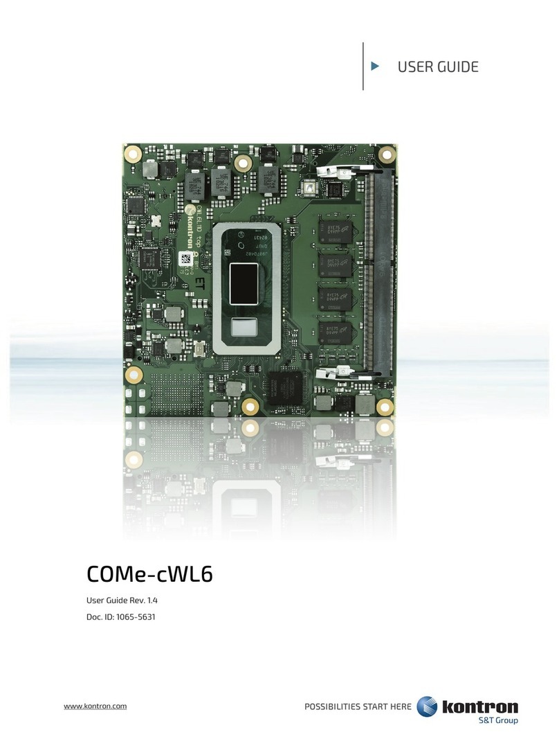
S&T kontron COMe-cWL6 User manual

S&T
S&T kontron KBox E-420-R1K/V1K User manual
