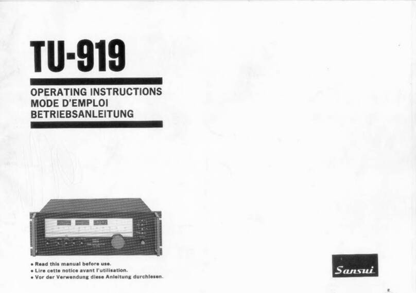
Sansui R-5 User manual

R-5
OPERATING
INSTRUCTIONS/MODE
D'EMPLOl/BETRIEBSANLEITUNG
We are
grateful
for
your
choice
of
this
fine
Sansui high
fidelity
product
.
Before
yo
u
operate
it .
we
suggest
that
you
read
this
booklet
once
through
carefully.
fam
il
iar
izing
yourself
with
the
important
precautio
ns,
operational
procedures and .every one
of
the
product
's
many
features.
It
will
help
to
ensure
that
you
will
avoid possible damage and
that
the
pro
-
duct's
superb
perfo
rmance
will
be
yours
to
enjoy
for
many
years
to
come.
Table
of
contents
Prec
aut
io
ns
2
Connections
. 3
Pan
el
inform
ati
r:
.. 6
Operating
pro~edures
8
Sorr
.e useful
hints
11
•.
necifica
tions
. . . . .
12
" )
he
Mode! No c:
·-
•
<;ct
rial
No.
of
your unit are
silown on its
lv.!1..
.
_
,i.n~
• Do not
lose
tt-
~
Warranty Card that carries
your unit's Model lllo.
and
Serial
No
.
•In
order
to
simplify the explanation illustra-
tions may sometimes differ from the originals.
•Design
and specifications subject to
changes
without
notice
for
improvements.
WARN
ING:
To prevent fire or
shock
hazard, do not
expose
this appliance
to rain or moisture.
Nous
sommes reconnaissants
pour
vo
tre
choix
de
ce
produit
Sansui
d'une
remarquable
haute
fidelite.
Avant
de
commence
r a
vous
en servir.
nous vous r
ecommandons
de
lire
cette
notice
completement
et
soigneusement, vous
familiari
-
sant ainsi avec
les
precautions
impo
rtant
es.
les
manceuvr
es
de
fonctionnement
et chacune des
nomb
reuses caracteristiques
de
l'appareil.
Cela
vous aidera a ne pas
provoquer
d'eventuels
dommages
et a
vous
permettre
de
profiter
pen-
dan
t
de
longues annees des superbes per-
formances
de
votre
appareil.
Table
des
matieres
Precautions
2
Conne
x
ions
..
3
Indications
sur le panneau . 6
Procoo
es
de
reg
I
age
. . 8
Oue
lques conseils
utiles
11
Specifications
..
.
12
•
Le
numitro du modele et
le
numero
de
9'rie
de l'appareil sont inscrits
sur
son
panneau
arri4re.
• Ne perdez
pas
la
carte de garantie ou
est
indi-
quee
le
numero du modale et
le
numero dans
la
s6rie du type
de
l'apparail.
•Pour
simplifier
las
explications,
les
illustra-
tions peuvent quelquefois
ltre
diffllrentes
des
originaux.
•
La
pr•ntation
et specifications sont
SU9C8P
·
tibles
d'ltre
modifi6es
sans
prtvis par suite
d'ameliorations eventuelles.
ATTENTION:
Pour eviter
les
dangers
d'electroa.ition ou d'incendie,
ne
pas
exposer cet appareil a·
la
pluie OU a
l'humidite.
Wir
mii
c
hten
zu dieser Gelr.igenheit unseren
Dank
aussprechen, daB Sie sici;
tur
diesen
HiFi
-
Baustein van Sansui entschieden haben.
Bitte
lesen Sie var
der
lnbetriebnahme
des Gerates
diese
Anleitung
sorgfiiltig
durch
,
um
sich
mit
den
wichtigen
VorsichtsmaBnahmen.
den
Be-
dienungsvorgangen
und
den
vielen
hervor
-
rangenden Eigenschaften dieses Gerates
vollstan
-
dig
vertraut
zu machen.
Miigliche
Beschadigun-
gen
kiinnen
dadurch
ve
rmieden
werden.
so
daB
Sie das hervorragende Leistungsvermiigen dieser
Komponent
e !Ur viele
Jahr
e genieBen
kiinnen
.
Inhaltsverzeichnis
VorsichtsmaBnahmen 2
Anschlusse . 3
Schalttafelinformation
. 6
Bedienungsverfahren 8
Einige
nutzliche
Hin
we
i
se
11
Tf"chnische Oaten
12
•Die
Modell- und die Seriennummer lhres
Geriites
sind
auf der Geratertickseite
ange
-
pben
.
• Verlieren Sie
bitte
nicht den Garantieschein,
auf dam die Modell-und die Seriennummer
dieser Einheit
angegeben
sind.
• Um die Erliiuterung
zu
vereinfachen, konnen
die Abbildungen manchmal vom Original
abweichen.
•
~nderunQen,
die dem technischen Fortschri
tt
dienen, bleiben vorbehalten.
WARNING
: Setzen
Sie
diese
Geriit
zur Verhutung
von
Feuer-
und
Strom-
schlaggefahr weder
Regen
noch Feu-
chtigkeit
aus.

2
Precautions
Bear in mind the following points.
Power plug
When
disconnecting
the
power
cord
from
the
power
outlet,
do
not
grasp
the
co
rd itself
but
th
e plug. Never co
nnect
or
disconnect
the
power
plug
with
wet
hands since
you
may
give
yourself
an
electric
shock.
*Disconnect
the
power
plug
from
the
outlet
when
you
do
not
inten
d
to
use
the
unit
for
a long
time
.
Do
not remove the case or
bottom
panel
Making ins
pections
or
adjustments
inside
the
unit
is
the
ca
use
of
trouble
and
electric
s
hocks
.
Do
not
.
under
any
circumstances,
poke
about
inside
the
unit
.
Installation precautions
Do
not
install
the
unit
in
the
types
of
location
given
belo
w
si
nce
the
unit's
performance
may
deteriorate
or
troub
le
may
be caused .
e
Locations
near heating appliances
or
other
heat-r
adiating
products
,
or
locations
exposed
to
dir
ect sunIight .
e
Locations
st.:sceptible
to
humidity
or
m
oi
s-
ture
.
e
Poorl
y
ventilated
or
dusty
locations
.
e
Locations
susceptible
to
vibration
or
loca-
tions
on
a slope
which
are
unstable
.
e Keep
the
unit
away
from
TV
sets
to
avoid
buzz noise.
Do not use thinners for cleaning
Wipe
.the
panels and case
from
time
to
time
with
a
soft
dry
cloth.
Using
thinners,
alcohol
or
other
volatile
liquids
can spoil
the
surfacing
or
cause
blotching
on
the
exterior
or
partial
erasing
of
characters, and
so
they
should never
be used. Also
remember
to
keep
insecticide
sprays
away
from
the
unit
.
Do not block
the
ventilation holes
Do
not place records
or
other
objects
over
the
ventilation
holes
on
top
of
the
unit
.
Blocking
these holes
will
raise
the
inside
temperature
whi
ch
may
result in
trouble
.
Precautions
Garder presents 6 l'esprit
les
points suivants.
Fiche d'alimentation
Lorsque
l'on
debranche
le
cordon
d'alimenta
-
tion
de
la
prise
d'alimentation,
ne pas
tirer
sur
le
cordon
lui-meme
mais sur
la
fiche.
Ne
jamais
brancher
ou
debrancher
la
fiche
d'alimentation
avec des
mains
hum
ides car
on
pourrait
recevoir
un
choc
electrique.
*
Debrancher
la
fiche
d'alimentation
de
la
prise
d'alimentation
lorsque
l'on
n'a pas
J'intention
d'utiliser
l'appar
eil
pendant
un
certain
temps
.
Ne pas retirer
le
coffret
ou
le panneau du
dessous
Le
fa
it
de
proceder
a des
verifications
OU
ades
reglages a
l'interieur
de
l'appareil
peut
entrainer
des pannes
OU
des chocs e
lectriqu
es.
Ne
jamais,
sous
aucun
prete
xte,
aller
farfouiller
a
l'in
-
terieur
de
l'appareil.
Precautions aprendre pour !'installation
Ne
pas installer
l'appareil
dans
des
endroits
tels
que
ceux
decrits
ci-dessous car cela
pourrait
entraver
les
performan
ces
de
l'appareil
ou
pro
-
voquer
des pannes.
e
Endroits
a
pro
x
imite
d'appareils
de
chauffage
ou autres appareils degageant
de
la
c
haleur,
ou
endroits
directement
exposes aux
rayons
du
soleii.
e
Endroits
exposes a
l'humidite
OU
a
la
buee.
e
Endroits
mal aeres
OU
poussiereux.
e
Endroits
exposes aux
vib
rati
ons
ou
en
pente
instable.
e Ne
pas
placer
l'appareil
pr
es
d'
un
pos e
de
television
pour
eviter les gres
ill
e
men
s.
Ne pas utiliser d'amincisseurs pour
le
nettoyage
E
ssu
yer
de
temps
en
temps
les
panneaux et le
ooffret
a l'
aide
d'un
chiffon
doux
et
sec.
Le
fait
d'utiliser
des amincisseurs, de
l'alcool
ou
tout
autre
liquide
volatile
peut
endommager
la
finition
,
faire
des taches sur
l'exterieur
de
l'appareil
ou
effacer
partiellement
les inscrip-
tions.
11
convient
don
e
de
ne jamais
utiliser
de
tels
produits.
Se
rappeler egalement
que
les in-
secticides
en
atomiseur
ne
doivent
pas
etre
utilises a
proximite
de
l'appareil.
Ne pas obstruer les orifices d'aeration
Ne
pas
poser
de
disqu
es
ou
tout
autre
obj
et
su
r
l
es
o
rifi
ces
d'aeration
pratiques
s
ur
le dessus
de
l'appar
eil. Le
fait
d
'o
bstruer
ces
orifices
pro
-
voque
une
hausse de
la
te
mperature
interieure
,
ce
qui
pe
ut
e
ntrain
er
un
mauvais
fonctionne-
ment.
VorsichtsmaBnahmen
Beachten Sie bitte folgende Punkte.
Netzstecker
Beim
Abziehen
des
Netzkabel
s
nicht
am
Kabel
sondern am Stecker ziehen.
Niemals
den
Netz
-
stecker
mit
nassen
Hiinden
einstecken
oder
abziehen,
da Sie sonst einen Stromschlag er-
leiden
kbnnen
.
• Wenn Sie das
Geriit
tur liingere
Zeit
nicht
benutzen
,
den
Netzstecker
abziehen.
Weder Gehiiuse noch Bodenplatte ent-
fernen
Ei
genmiichtige
lnspketionen
oder
Ein
stellungen
am
Ger
iite
inneren
kbnnen
di
e Ursache von
Stbrungen
o
der
Stromschlagen
se
in.
Stochern
Sie
unter
keinen
Umstiinden
im
Ger
iitei
nneren
herum
.
VorsichtsmaBnahmen beim Aufstellen
Stellen Sie das
Geriit
nicht
an den
nachfolgen
-
den
Orten
auf,
da
die
Leistung sich
ve
r
sc
h-
lec
htern
kann
oder
Stbrungen
auftreten
kbnnen
.
e
Orte
in
der
Niihe
von Hei
zkbrpern
oder
son-
st
ig
en W
iirmeque
llen,
oder
Orte,
die
direkter
So
nn
eneinstrahlu
ng
ausgesetzt sind.
e
Orte
,
die
Feucht
i
gkeit
oder N
iisse
ausgesetzt
sind.
e S
chlech
t
beluftete
oder
staubi
ge
Orte.
e
Orte
,
die
Vibration
en aisgesetzt sind,
oder
un
-
s
tab
ile
Orte
auf
Schriigen.
• Dieses
Ge
r
iit
m6glichst
entfernt
von Fern
se
h-
ge
riiten
aufstellen.
um
induziertes
Brummen
zu
ve
rm
eiden.
Zurn
Reinigen keine Verdunnungsmittel
benutzen
Front
-
und
Ruck
platte
sowie
Gehiiuse ab
und
zu
mit
einem
weichen
.
trockenen
Lappen
abwischen.
Verdunner
, A l
kohol
oder
so
nstige
leichtfluchtige
Flussigkeiten soll
ten
niemals
zum
Reinigen
benutzt
werden
, da sie
die
Oberfl
ache
angereifen
und
Kraterbildung
auf
den
Aul?.en-
wiinden
ode
r
teilweise
Ablbsung
der
Schriftzuge
verursachen
kbnnen.
Auch
sollten
Sie
lnsekten
-
s
pr
ay
vom
Ger
at
fernhalten
.
Nicht die Ventilationsschlitze blockieren
Keine Schallpl
atte
n
ode
r sonstige Gegenstande
auf
die
Ventilationssch
l
itze
legen
Dur
ch
Bl
ockie
ren dieser Sch
lit
ze
s
teigt
die
lnnen
tem·
peratur
. was
zu
Stb
rungen fuhren
kann
.
For
the United
Kingdom
only----
----
---------..
Important
The
wires
in
this
mains l
ead
are co
loured
in
accordance
with
the
following
code:
Blue:
Neutr•I
Brown: Live
If
the
colours
of
the
wires
in
the
mains lead
of
this
equipment
should
not
correspond
to
the
coloured
markings
identifying
the
ter-
minals
in
your
plug
, proceed
as
follows
:
The
wire
which
is
coloured
blue
must
be
connected
to
the
terminal
which
is
marked
with
the
letter
'N'
or
coloured
black
.
The
wire
which
is
coloured
brown
must
be
connected
to
the
terminal
which
is
marked
with
the
letter
'L'
or
coloured
red.
Ensure
that
your
equipment
is
connected
correctly
.
If
you
are in
any
doubt
,
consult
a
qualified
electrician
.
For
equipment
purchased
outside
the
U.K.
with
a "EUROPEAN"
two-pin
mains
plug,
the
plug
should be removed and
connections
made in
accordance
with
the
above
instruc-
tions
. Ensure also
that
the
equipment
is
properly
adjusted
to
240
volts
operation
.
If
you
are
in
any
doubt,
consult
a
qualified
electrician
,
or
our
Service
Agent
in
the
U.
K.

Connections Connexions
75n 300n
fi
[lO
: I
~
-------
------J
I
I
--------"
,,
____________
..,
I
I
I
I
I
I
I
I
I
LINE
IN
~-,_....
~~L..L.~o-fl~--,
/
+ L -
LINE
OUT
----
•I
n
stru
c
tions
and
requirements
indicated
may
va
ry to
so
me
extent
depending
on
sales area,
local laws and regulations.
Connection precautions
•When
connec
ting
or
re-locating
the
unit,
be
sure
to
turn
the
power
off
or
disconnect
the
power
cabl
e.
•Be
su
re
not
to
confuse
the
right
channel
with
the
left ,
pl
us cables
with
minus
or
inputs
with
ou
tputs
. Check each s
tep
carefully
.
•U
se
con
nection
cor
ds
of
dependable
quality.
Check
that
connect
ions are secure and
that
connect
i
ng
leads are
not
frayed
or
in
contact
with
o
ther
objects.
Poor
connection
may
cause
hum
noise
or
breakdown
.
• Les
instructions
et
les
reglementation
in
diquees
peuvent
varier
suivant
la
region, les
lois
et
l
es
reglement
s loc
au
x.
Precautions aconnexions
•
Ouand
vous branchez
l'appareil
ou
si
vous
l'in-
stallez dans
un
nouvel
endroit,
assur
ez
-vous
de
couper
l'alimentation
ou
de
deconnecter
le
cable
d'alimentation.
• S'assurer
de
ne pas
confondre
le
canal
dro
it
avec le canal gauche,
les
cables
de
polarite
positive
et ceux
de
polarite
negative et les en-
trees et les sorties. Contr61er chaque etape
soigneusement.
•
Utiliser
des
tils
de
connexion
de
bonne
qualite.
S'assurer
que
les
connexions
soient
parfaites
et
que
les
tiites
denudees des
fils
ne
soi
en
t pas cisaillees
ou
en
contact
avec d
'-
autres
objets.
De
mauvaises
connexion
peu-
vent
etre
la
cause
de
grondements
ou
meme
d'une
panne
de
l'appareil.
3
Anschlusse
-L + -R +
+ R -
•Die
Anleitungen
und
angegebenen
Werte
konnen
in
Abhiingigkeit
vom Ve
rk
aufsgebiet
und
den
art
lichen
Ge
se
tzen e
twa
s
abweichen
.
VorsichtsmaBnahmen beim Ansch-
lieBen
•Zurn
An
sc
hli
er..e
n
bzw
.
wenn
der
Aufstellung
-
so
rt
dieses Ge
riite
s
geiindert
wird,
unbedingt
den
Netzs
c
halter
ausscha
lten
und
da
s
Netz
-
kabel abziehen.
•
Nicht
den
recht
en
Kanai m
it
dem
linken,
positive
mit
negativen
Ka
beIn
bzw
. Eingiinge
mit
Ausgiingen
ve
rwechse
ln
. Nach
dem
Ansch-
liel>en
unbedingt
jede einzelne
Komponente
uberprufen
.
•
Nur
Verbindungskabel
hoher
Oualit
iit
benutz
-
en.
Auf
richtigen
Anschlul>
achten
und
uber-
prufen,
dal>
die
Kabel
nicht
beschiidigt sind
bzw
. Kurzschlul> verursachen.
Fa
lscher
Ansch
-
lul>
kann
zu
Brumm
tuhren
oder
de
s
Geriit
beschiidigen.

Speaker
systems
To
SPEAKERS
SYSTEM-A
or
B
terminals,
con-
nect speaker cords
taking
care
not
to
confuse
the
right
channel
with
the
left,
the
plus
polarity
with
the
minus.
•Be
sure
that
exposed leads are
firmly
secured
to
the
terminals.
Turntable
Connect
your
turntable
to
the
PHONO
ter-
minals.
If
your
turntable
is
equipped
with
a
grounding
cable.
connect
it
to
the
unit's
GND
terminal.
But
disconnect
it
if
you
notice
in-
creased
hum
.
•If
your
turntable
has a
crystal
or
ceramic car-
tridge,
connect
it
to
TAPE/AUX
inputs,
not
PHONO
inputs
.
Tape
deck
Connect
the
unit's
TAPE
REC
terminals
to
the
line
input
terminals
of
your
tape
deck.
and
the
unit's
TAPE
PLAY
terminals
to
the
output
ter-
minals
of
the
deck.
AC
power outlets
This
unit
is
provided
with
auxiliary
AC
outlets
which
are
handy
for
connecting a cassette deck
or
turntable
to
supply
power
to
these
units
.
SWITCHED
(100W
capacity) : The power
of
the
connected
components
is
switched on and
off
when
the
unit's
POWER
switch
is
operated.
UNSWITCHED
(150W
capacity) :
The
p
ower
is
supplied
to
the connected
components
re
-
gardl
ess
of
the
position
of the
unit's
POWER
s
witch
.
NOTE: Depending on the laws and
regu-
lation enforced locally. models
without
AC ou
tlet
smay
be
supplied
to
some
areas
.
Also, depending on the
sales
area, the
shape
of
the AC outlets
and
their
capacity
may
differ
.
R-5
Enceintes
Pour
les
brones
SPEAKERS
SYSTEM-A
ou
B,
connecter
les
cables des enceintes en
prenant
bien
so
in
de
ne pas
confondre
le canal
droit
et
gauche et
la
polarite
positive.avec
la
negative.
•Bien
s'assurer
que
les
parties exposees des
conducteurs
sont
bien fixees dans
les
bornes.
Tourne-clisque
Raccorder
votre
tourned
-disque aux
terminau
x
PHONO
. Ouand
votre
tourne-
disque est
mun
i
d'un
cable de Mise ala terre.
ra
ccorder le sur le
terminal
GND
de l'appareil.Mais deco
nn
ectez le
si
vous remarquez une augme
nt
at
ion
a
no
r
ma
le
du
ronflement
.
•Si
votre
tourne-disque
possede une
cartouche
de
cristal
ou
ceramique,
la
connecter aux
entree
TAPE/AUX
au lieu des entrees
PH
ONO
.
Magnetophone
Raccorder
les
bornes
TAPE
REC
de
l'appareil
aux bornes
d'entree
de
votre
magnetophone
et
les
bornes
TAPE
PLAY
de
l'appareil aux bornes
de
sotti
e
de
votre
magnetophone
.
Prises
d'alimentation CA
Cet appareil est equipe
de
prises
CA
auxiliaires
qui
sont
pratiques,
lorsque
l'on
veut
brancher
un
magnetocassette
ou
une
platine
tourne-
disque.
pour
leur
fournir
l'alimentation
elec-
trique
.
SWITCHED
(capacit6
de
100
WI:
Les
compo
-
sants relies a l'appareil sont sous tension ou
hors tension lorsque
l'on
actionne
l'interrupteur
POWER de l'appareil.
UNSWITCHED
(capacit6
de
150 W):
L'ali
-
mentation
est
fournie
aux divers elements relies
quelle
que
soit
la
position
sur laquelle
se
trouve
l'interrupteur
POWER
de
l'appareil.
REMARQUE:
En
raison
des
lois et regle-
ments
en
vigueur
dans
certaines regions,
ii peut arriver que
des
modeles
ne
soient
pas
equipes
de
prises d'alimentaion
en
courant alternatif.
De
meme,
la
forme et
capacite
de
ces
prises varient egalement
d'apres
les
regions ou
les
appareils sont
mis
en
vente.
Lautsprecherboxen
An
die
mit
SPEAKERS
SYSTEM
-A o
der
B be-
zeichneten Klemmen sind die Lautsprecherkabel
anzuschliel1en; dabei j
edoch
darauf
achten.
daf5
der re
chte
nicht
mit
dem
linken
Kanai und
der
p
ositive
Lei
ter
nicht
mit
dem
neg
ativen ver-
wechselt w ird .
• Dara
uf
a
chten
,
daf5
die blanken
Leiter
richtig
an
den
Kl
emme
n
ges
ichert sind.
Plattenspieler
I ren Plattenspieler an d ie Klemmen
PHONO
ansch
li
ef5en
; Wenn Ihr Pl
at
enspieler
mit
einem
Erdungskabel ausgestanet i
st
, d
ieses
an
die
lemme
GND
des
Geriite
s anschlief5en; falls
jedoch
dadurch
der
Br
umn
ve
rstiirkt
wi
rd, das
Erdungskabel wieder abklemmen.
• Wenn Ihr Plattenspieler einen Kristal
I-
oder
Keramiktonabnehmer
hat,
so
schlie11en
Sie
ihn
bitte
nicht
an die
PHONO
-Eingiinge
sondern an
die
TAPE/AUX-E
ingiinge an.
Tonbandgerat
Die
KlemmenTAPE
REC diesesGeriites
mit
den
Eingangs-und
die
Klemmen
TAPE
PLAY
mit
den Ausgangsklemmen des Tonbandgeriites ver-
binden
.
Kaltgeratesteckdosen
Dieses
Geriit
ist
mit
zusiitzlichen Kaltgeriite-
steckdosen ausgestattet.
die
zweckmaBigerweise
zum
Anschluf5 eines Cassettendecks
oder
eines
Plattenspielers verwendet werden
kiinnen
.
SWITCHED
(100
W Kapazitiit): Die ange-
sc
hl
osse
ne
Komponente
wird
durch
Betiitigen
des Schalter POWER des Geriites ein-und
ausgeschaltet.
UNSWITCHED
(150
W Kapazitiit):
Die
ange-
schlossene
Komponente
wird
oh
ne Rucksicht
auf
d
ie
Stellung des Schaller POWER des
Geriites
mit
Strom
versorgt.
ANMERKUNG:
Je
nach den
ortlich
geltenden Gesetzen und Bestimmungen
werden
fUr
manche Importgebiete
au
ch
Gerate ohne Netzausgangsbuchsen
ge
-
1iefert.
Auf:/,erdem
ist die Form und
Kapazitat der Netzausgangsbuchsen je
nach Verkaufsgebiet verschieden.

I
!HM
I 3000
~--
T
-shaped
Antenna Connection
Connect
the
ends
to
the
FM
300n
antenna
ter
-
minals, spread
the
two
arms
of
the
"T
"
apart,
adjust
the
direction
of
the
antenna
while
listen-
ing
to
a broadcast
so
as
to
locate
the
optimum
reception
, and
th
en s
ec
ure
the
antenna
to
th
e
ceiling or
wall
. Secure it
as
high
as
possible.
If
it
is
spread
horizonta
lly in a
low
location,
recep-
tion
may become
un
sta
ble
every
time
s
ome
-
body
passes
by .
*
Erect
an
ou
t
do
or
FM
an
te
nna
fo
r
FM
recep-
t
ion
with
a good s
ou
nd
qu
ality and minimal
noise.
The
accessory T-shaped a
nt
enna is a
make-
shift
antenna
to
serve
un
til
yo
u install
an
outdoor
FM
antenna.
Outdoor
FM
Antenna Connection
Either
300-0hm
feeders
or
75-ohm
coaxial
cables
may
be used
as
the
lead-
in
wire
that c
on
-
nects
the
tuner
to
the
outdoor
FM
antenna
.
Connection
using
300-ohm feeder : Process
the
ends of
the
feeder
as
in
the
figure
and co
nnect
them
to
the
FM
300n
antenna terminals.
Connection
using
75-ohm coaxial cable:
Pr
o
cess
the
end
of
the
coaxial cable
as
in
the
figure
and
co
nnect
it
to
the
FM
75n
antenna
terminal.
AM
antenna
The
antenna provided inside
the
unit
is ade-
quate
for
quality
reception
of
nearby
AM
sta-
tions
. However,
if
you
c
annot
obtain
the
desired
results
with
the
built-in
ferrite
bar antenna,
c
onnect
a
vinyl-c
l
ad
wire
to
the
AM
antenna
terminal
, extending
it
outdoors,
if
possible.
How
to
use
TAPE/AUX
inputs
"AUX"
means aux
iliary,
and
the
TAPE/
AUX
inputs
have
the
same electrical
function
as
the
TAPE
PLAY
inputs
.
They
therefore
connect
a
tape deck, an
adaptor
for
special
cartr
idges, and
other
equipment
that
has
about
the
same
output
level
as
the
afore-mentioned
compo-
nents.
Raccordement de l'antenne
en
"T"
Raccorder
ses
ex
tremites
au
x bornes
d'antenne
FM
300n,
deployer
les
deux bras
du
"T"
et
determiner
la
direction
qui
assure
la
meilleure
reception
possible en
ec
o
utant
une emission;
fixer
alors
l'antenne
a une
paroi
ou au
plafond,
le
plus
haut possible en
tous
cas
. Si elle est
placee a
l'hori
z
ontal
e et t
rop
bas.
la
reception
sera
instable chaque
fo
is
que
quelqu'un
passera
a prox
imite
.
• Une antenne
FM
installee a l'exte
rieur
as-
su
re
ra
un
son
de
bonn
e qualite
et
contri
-
bue
ra
a redu
ir
e l
es
parasites. L'
antenne
en
"T
"
fourni
e c
omm
e acce
sso
ire pourra servir
provisoireme
nt
jusqu'a i
nstallation
d'une
bo
nne antenne AM ex
te
rieure.
Raccordement d'une antenne
FM
exterieure
On
pourra
u
ti
liser soit une descente d'
antenne
300
ohms,
soit
un
cable coaxial
75
ohms
pour
le
raccordement
du
tuner
a une aritenne
FM
ex-
ter
ieure.
Reccordement
Ii
l'aide d'une descentll
300
ohms: Preparer les
extrem
it
es
de
la
descente
d'antenne
comme
illustre
sur
la
figure
et
les
rac-
corder
aux bornes
d'antenne
FM
300n
.
Raccordement
Ii
l'aide d'un clible coaxial
75
ohms: Preparer
l'e
x
tremite
du
cable coaxial
comme
illustre
sur
la
figure
et
brancher
celle-ci
dans la
borne
d'antenne
FM
75n.
Antenne
AM
L'
antenne
fouri;iie s'avere adequate
pour
une
re-
ce
ption
de
qualite
des stations
AM
avoisinantes.
Mais s'il
est
impossible d'
obtenir
une
reception
corr
ec
te
en
utilisant
l'
ant
enne
AM
de
ferrite,
raccorder
un
co
rdon
PVC a
la
borne
d'
antenne
AM
puis
la
disposer a
l'
ext
erieur.
Comment utiliser
les
entrees
TAPE/
AUX
"
AUX"
signifie
au
x
iliare
,
les
entrees
TAPE/
AUX
ont
la
meme
fonction
electrique
que
les
entrees
TAPE
PLAY.
Elles servent a brancher
un
magnetophone
,
un
adaptateur
pour
car-
touches
speciales
et
d'autres
equipements
qui
ant
a peu pres la
meme
puissance
que
les
com-
posants
mentiones
ci-Oessus.
5
AM
-----='
AnschluB der T-fOrmigen Antenne
Die Enden an
die
mit
"FM
300n'
' bezeichneten
An
t
ennenklemmen
anschlie15en,
die
beiden
Arme
des " T" auseinanderspreizen,
die
Antenne
beim
Horen
einer
Rundfunk
sendung
auf
opti-
malen Empfang ausric
hten,
dann
die
Antenne
an einer Dec
ke
oder Wand
miigl
ichst h
oc
h be-
festigen. Wird sie horizontal auseinanderge-
s
preizt
an einer niedrigen Stelle befestigt, kann
der
Empfang unstabil
werden
,
wenn
Per
sonen
vorbeigehen.
• Eine
UKW
-Aul5ena
ntenne
mont ieren,
um
einen
UKW
-
Empfang
mit
guter
Klangquali
tat
und
minimalem
Gerau
sc
h erzielen zu
kiinn
en.
Die
mitgelieferte
T-
fiirm
i
ge
Antenne
ist
nur
eine Behelfsantenne,
die
bis
zum
Montieren
einer
UKW
-Au15enantenne verwendet werden
kann.
AnschluB der UKW-Antennen
Entweder
300
-
0hm
-Speisekabel o
der
75
-
0hm
·
Koaxialkabel
kiinnen
als
Zul
ei
tung
ve
rwendet
werden,
die
den
Tuner
mit
der
UKW
-
Au15en
an·
tenne
verbindet
.
AnschluB bei Verwendung
eines
300-0hm
-
Speisekabels:
Die
Enden desSpeisekabels
gema15
Abbildung
vorbereiten
und
an
die
mit
"FM
300n"
bezeichneten
Antennenklemmen
an-
schliel5en.
AnschluB bei Verwendung
eines
75-0hm
-
Koaxialkabels:
Da
s Ende des Koaxialkabels
gemal5
Abbildung
vorbereiten
und
diesen an
die
mit
"
FM
75n''
bezeichne
te
Antennenklemme
anschlie15en.
MW-Antenne
Die
se
inn
e
rh
a
lb
desGerat
es
ver
se
hende
Ant
enne
is
t ausreichend f
i.i
r
Ou
al
it
at
se
mpfan
g von MW·
Sendern in der Nahe. Wenn der gewi.in
sc
hte
Empfang
nur
mit
der
Ferri
stabantenne f
i.i
r
Mittelwell
e nic
ht
m
ii
glich
ist,
so
sc
hlie
en Sie
ein PVC-Kabel an
di
e
Antenn
e
nklemme
fi.ir
Mittelwell
e an le
it
en Sie
es
m
ii
glichst bis
na
ch
draul5en.
Verwendung der
TAPE/AUX-
Eingange
Die
mit
TAPE/AUX
bezeichneten Reserveein-
gange haben
die
gleiche elektrische
Funktion
wie
die
Eingange
TAPE
PLAY
. Daher
kiinnen
an diese Eingange ein Tonbandgerat , ein
Adapter
fur
Tonabnehmer
oder
ein anderes Gerat
(mit
ungefar
dem
gleichen Ausgangspegel.
wie
die
vorher
erwahnten
Komponenten
) angeschiossen
werden.

6
Panel information Indications sur
le
panneau Schalttafelinformation
13 14
n
..
0 . G.
r
I n-l
rr
~
.___,...._....,
-
1 2 3 4
1 POWER Switch
Push
the
PO
WER
sw
itch
once
to
turn
the
unit
on,
once
more
to
turn
it
off
.
2 PHONES
Jack
When
you
want
to
listen
through
headphones
privately.
inse
rt
the
headphone plug
into
the
PHONE
S jack and
turn
the
SPEAKERS
switch
off.
3 SPEAKERS Switches
The
y select
the
speaker systems
(A
and
Bl
to
which
signals are sent
for
reproduction.
When
se
t
to
ON,
the
switch
permits
the
unit
to
send
signals
to
the
selected speaker systems.
4
BASS
Tone Control
Thi
s
is
used
to
adjust
the
bass
and
low
-
fre
-
quency
-range sound
in
accordance w
ith
the
acoustics
of
the
listening
room
and
your
per-
sonal pre
fe
ren
ce
.
When set
to
the
DEFEAT
position.
the
fre-
quency
response
is
made
flat.
Wh
en
rotated
to
the
right
.
the
bass
is
emphasized and
when
rotated
to
the
l
eft,
it
is
deemphasized.
5 TREBLE Tone Control
Thi
s
is
used
to
adjust
the
treble
or
high-fre-
quency
-range
so
und such
as
that
from
cymbals.
When r
otated
to
the
right
from
the
DEFEAT
posit
ion
.
th
e
treble
is
emphasized and
when
rotated
to
the
l
eft,
it
is
deemphasized .
6 BALANCE Control
The
volume
of
the
left
and
right
spe
akers can
be adjusted
by
the
BALANCE
control.
As
the
control
is
turned
counterclockwise
from
the
c
enter
position
,
the
sound
from
th
e
left
speaker
becomes
louder
than
t
ha
t
from
the
ri
ght
speaker, and vice versa.
7
VOLUME
Control
It
adjusts the o
utput
level
(volume
)
of
your
audio
system.
The
mo
re
to
the
right
it
is
turned,
the
greater
the
v
olu
me.
5 6 7 8
910
1 lnterrupteur d'alimentation (POWER)
Appuyer
une
fois
sur
le
bouton
POWER
pour
mettre
l'app
areil en
fonction
, et une
deuxieme
fa
is
pour
I'arri!!ter.
2
Prise
de
ca~ue-ecouteurs
(PHONES)
Ouand vous desir
ez
ecouter
de
la
musique
a
!'aide
d'un
casque.ecouteur
s,
introduire
la
fiche
du
ca
s:i
ue-ecouteurs dans
la
prise
PHONES
et
couper
le
commut
ateur
SPEA
KE
RS
.
3 Commutateurs d'enceintes
acoustiques
(SPEAKERS)
Ces
commutateurs
servent aselectionner l
es
en-
ceintes acoustiques
(A
et B) auxquelles
sont
en-
voyees les signaux
pour
la
repr
od
uc
t i
on
.
Ouand
ii est sur
la
position
ON.
le
commuta
teur
permet
a l'appareil
d'envoyer
les
sign
au
x aux
enceintes acoustiques
choi
s
ies
.
4 Commande
des
tonalites
graves
(BASS)
Elle sert a ajuster
les
gra
ves
ou
le sons
de
la
plage
basses
frequences en
fonction
de
l'acous-
tique
de
la
salle d'ecoute et
de
ses
preferences
personnelles.
Ouand ii est place a
la
position
DEFEAT
,
la
correction
de
la
reponse
de
frequence est
annulee. Une
rotation
de
la
commande
vers
la
droite
acce
ntue
les
graves,
tandis
qu
'une
rota
-
tion
agauche les
reduit
.
5 Commande
des
tonalites
aigues
(TREBLE)
Ell
e sert a ajuster
les
aigues
au
l
es
sons
de
la
plage hautes frequences tels
que
ceux d
es
cym-
bales.
Un
e
rotation
a
droite
a
part
ir
de
la
posi-
tion
DEFEAT
accentue les aigues,
tandis
qu'une
rotation
agauche
les
reduit
.
6 Commande d'equilibrage (BALANCE)
Le
volume
des enceintes acoustiques gauche et
droite
pe
ut
etre
regle par
la
commande
BAL
-
ANCE.
Si
la
commande
est
tourne
dans le sens
contraire
des aiguilles
d'une
montr
e a
partir
de
sa
position
mooiane, le son
de
l'enceinte
acous-
tique
gauche
sera
accentue par
rapport
a celui
de
l'enceint
e acoustique
droite,
et vice-versa.
7 Commande
de
volume
(VOLUME)
Cette
com
mande sert aregler le niveau
de
sortie
(volume
sonore)
de
votre
ensemble stereo. Plus
ii est
tourne
vers la
droite.
plus
le niveau
du
son
est eleve.
11
12
1 Netzschalter (POWER)
Drucken
Sie den Schalter POWER
zum
Ein
-
schalten des Geriites. drucken Sie ihn erneut
zum
Ausschalten.
2 Kopfhorerbuchse (PHONES)
Fur ungest6rtes H6vergenligen ein Paar HiFi-
Stereo-
Ko
pfh6rer
an die Buchse
PHONES
ansch-
lie
l1
en
un
d den Sc
halter
SPEAKERS
abschalten.
3 Lautsprecherschalter (SPEAKERS)
An
d
ie
ses
Gerat
konnen
bis zu z
we
i Boxenpaare
angeschlossen werden,
die
uber diese beiden
Schalter in
Betri
eb gesetzt werden
k6nnen
.
Wenn
auf
P
osition
ON gestellt .
dann
erm6glicht
d
iese
r Scha
lt
er
die
Absteuerung des aus-
gewiihlten B
oxen
paares.
4 Tiefenregler (BASS)
M
it
Hilfe
dieses Reglers
die
Wiedergabe
der
tie
fen T
on
e je nach Geschmack
und
Chara-
teristik
des
Abh6rraums
einstellen.
In
der
Stell
ung
DEFEAT
(
Au
s)
werden
d
ie
Fre-
quenzen
linear wiedergegeben.
Durch
Drehen
nach rechts
werden
die
tiefen
Frequenzen ange-
hoben
und
du
rch
Drehen
nach li
nk
s a
bg
e-
sc
hwiicht
.
5 Hohenregler (TREBLE)
Mit
di
ese
m Regler kann
die
Wiedergabe van
hohe Frequenzen,
wie
z.B.
der
Ton
van Becken.
beeinflul1t werden. Bei Drehen nach rechts
werden
die
hohen Frequenzen angehoben, bei
Drehen
nach
links
abge
sc
hw
iicht
. In
der
Stellung
DEFEAT
(Aus)
verliiuft
der Frequenzgang
linear.
6
Balanceregler
(BALANCE)
M
it
dem
Reg
ler
BALANCE
kann
die
Lautstiirke
der
linken und rechten Lautspr
ec
her eingestellt
werden
.
Durch
Drehen
des Reglers
aus
der
Mittelstellung
nach links
wird
der
linke
Laut
-
sprecher lauter als
der
rec
hte
und
umgekehrt
.
7 Lautstiirkeregler
(VOLUME)
Mit
d
iese
m Regler
wird
der Ausgangspegel Ihrer
HiFi
-Anlage geregelt. Den Regler nach rec
ht
s
drehen.
um
die
Laut
stii
rke
zu erhohen.
I
J

8 LOUDNESS Switch
Depressing
this
switch
when
listening
at
a
low
volume
level accents
the
lows and highs
pro
-
perly
to
render
the
reproduced sound
more
realistic.
This
compensates
for
the
fact
that
the
human ear becomes insensitive
to
the
lows and
highs
as
the
sound
volume
is
reduced.
9 FM
MUTING/MODE
Switch
This
switch
has
a dual
function
:
it
switches
the
muting
circuit
on and
off
and
it
switches
the
reception
mode
between
AUTO
and
MONO.
No
rmally
this
switch
is
used
at
the
"ON/AUTO
"
position
.
Th
e
muting
c
ircuit
is
activated and
the
annoying i
nterstation
noise inherent
to
FM
reception
is
cut
out
fo
r noise-free
tuning
.
Fur
t
hermore
. FM stereo broadcasts can be
heard in stereo
while
FM
mono
broadcasts are
hea
rd
in
mono
.
Depress
this
switch
to
the
"OFF/MONO
" posi-
tion
to listen
to
an
FM
program whose weak
signals have been
cut
off
by
the
muting
circuit
together
with
th
e noise
or
to
listen
to
a stereo
broadcast in
mono
.
10 TAPE
MONITOR
Switch
Push
one
when
wanting
to
hear a tape
or
moni
-
tor
a recording.
SOURCE: Operate this
switch
when
hearing
records and radio programs
but
not
tapes.
TAPE: Push
this
switch
when
hearing tapes
played on a tape deck connected
to
the
rear-
panel
TAPE
PLAY
terminals.
11
Selector
Switches
Th
es
e s
witche
s are used
to
se
lect the pr
og
ram
source.
PHONO:
For
listening
to
a record
on
the
turntable
connected
to
the
PHONG
termi
-
nals.
FM:
For
listening
to
an
FM
broadcast.
AM:
For
listening
to
an
AM
broadcast.
TAPE/AUX:
For
using a
component
connected
to
the
TAPE/
AUX
terminals.
•Push
in one
switch
to
select the program
source.
12
TUNING
Control
Use
it
to
tune
in
on
the
frequency
of
a desired
AM
or
FM
station
.
13 SIGNAL Indicators
Indicators
1
through
5
light
in
line
with
the
strength
of
the
signals received
by
the
antenna
to
indicate
the
signal strength.
14 Tuning Indicators
During
FM
reception,
the
triangular
indicators
on
the
left
and
right
of
the
center
indicator
light
to
indicate
the
optimum
reception
point
.
If
the
station
has
not
been tuned in
properly.
the
left
or
right
indicator
will
go
off
.
In
cases
like
this,
the
reception
points
shifts
in
the
direc
-
tion
indicated
by
the
triangular
indicator
which
has lighted.
The
triangular.
indicators
both
go
off
when
the
reception
point
has
sh
i
fted
com-
pletely
.
The
left
and
right
triangular
indicators
do
not
light
during
AM
reception.
8 Commutateur
de
controur
sonore
(LOUDNESS)
En enfonc,:ant
ce
commutateur
lors de
l'ecoute
afaible niveau sonore, cela
permet
d'accentuer
les graves
et
aigus
de
fac;:on
convenable
pour
donner
un
effet
plus realiste des sons repro-
duits
. Cela compense
le
fait
que
l'oreille
humaine
devient
insensible
au
x graves
et
au
x
aigus amesure que le
volume
sonore-est
reduit
.
9 Commutateur
de
sourdine
FM/Mode
(FM
MUTING/MODE)
II
remplit
deux
fonctions
. asavoir
qu
'il
allume
et
eteint
le
circuit
de sourdine en
FM
et
qu'il
pe
rmet
d'
effectuer
le
passag
e e
ntr
e
les
modes de
rec
eption
AUTO
et
MONO
. En temps
normal,
le laisser a
la
position
"O
N/AUTO".
ce
qui
place alors
en
service le
cir
c
uit
de sourdine
qui
elimine
les
bruits
desagreables inherents a
la
re-
ception
FM et permet une s
yntonisation
ex-
empte
de parasites. En o
utre
, les emissions
FM
stereo sont alors re
c;:
ues aut
omatiquement
en
stereophonie et
les
emissions FM monaurales le
son en
monophonie
.
On enfoncera
ce
co
mmu
tat
e
ur
a
la
Position
"
OFF/MONO"
pour
l'eco
ut
e
d'u
n programme
FM
dont
les
signaux de
ja
faibles sont encore
attenues par le circ
uit
de sourdine
en
meme
temps
que
les
bruits
. ou bien
pour
l'
e
coute
en
monophonie
d'une em ission stereo.
10 Commutateur
de
surveillance
de
bande
(TAPE
MONITOR)
Enfoncez-en
un
quand vous desirez entendre
une bande
ou
controler
un enregistrement.
SOURCE:
Utilisez
c
et
i
ntenupteur
quand vous
ecoutez des disques OU des emissions rad io
mais
pas
des bandes.
TAPE: Enfoncer cet
interrupteur
quand vous
ec
outez
des band
es
reproduites sur une
platine
de magnetophone raccordee aux
bornes
TAPE
PLA
Y
du
panneau arriere.
11
lnterrupteurs
de
slilecteur
Ces
interrupteurs
permettent
de choisir
la
source de programme.
PHONO: Pour ecouter un disque
reproduit
par
la
platine
tourne-disque reliee aux
bornes
PHONG
.
FM:
Pour ecouter une emission
FM.
AM:
Pour ecouter une emission
AM
.
TAPE/AUX:
Pour
faire
fonctionner
un
compo-
sant relie
au
x bornes
TAPE/AUX
.
•
Enfoncer
l'un
des
interrupteurs
pour
choisir
la
source
de
progr
amme
.
12
Commande
de
syntonisation
(TUNING)
L'utiliser
pour
s'accorder sur
la
frequence de
la
station
FM
ou
AM
desiree.
13
Hmoins
SIGNAL
Ces
temoins
de
1 a5
s'allument
en
fonction
de
l'intensite
des signaux
rec;:us
par l'antenne.
14
Hmoins
d'accord
A
la
reception
FM.
les
temoins
triangulaires
de
part
et d'
autre
de
l'indicateur
central
s'allument
pour
signaler le
point
c;Je
reception
optimal.
L'
un
au
l'autre
temoin
s'
eteint
si
!'accord n'est
pas
parfait.
Dans
ce
cas,
le
point
de reception
optimal
doit
lltre
recherche dans
la
direction
du
temoin
allume. Lorsque !'accord est complete-
ment
decale,
les
deux
temoins
triangulaires
s'eteignent. Les
temoins
triangulaires
de
gauche
et
de
droite
sont inop9rantsa
la
reception
d'une
emission
AM
.
7
8 GehOrrichtige Lautstiirkekorrektur
(LOUDNESS)
Durch
Druck
auf diese Taste beim
Horen
mit
geringer
Lautstiirke
werden
die
Tiefen
und
Hohen
richtig
akzentuiert
,
um
die
Tonwieder
-
gabe realistischer zu machen.
Hierdurch
wird
for
die
Tatsache
kompensiert,
da~
das men-
schliche
Ohr
bei verringerter
Lautstiirke
unemp
-
findlich
fUr
tiefe
und hohe
Tone
wird.
9 UKW-Stummabstimmungs-/Betriebsar-
tenschalter (FM MUTJNG/MODE)
Dieser Schalter hat zwei
Funkt
ionen: er
sc
haltet
di
e Stummabsti
mmung
ssc
haltung ein und
au
s
und die Empfangsbetriebsart zwi
sc
hen
AUTO
und
MONO
um
.
Normalerweise
wird
die
ser Scha
lt
er auf "ON/
AUTO
" eingeste
llt
. Dabei
wird
die
Stumm
·
abs
timmung
ss
chaltung eingeschaltet.
um
da
s bei
der UKW-Senderwahl
auftretende
s
torend
e
Rau
sc
hen
zwi
sc
hen den Sendern fur
ei
ne
rau
sc
hfreie
Ab
s
timmung
zu unterdrUcken.
Au~
erdem
si
nd UKW-Stereosendungen ste
reofoni
sc
h
und
UKW
-Mon
os
endungen
monofon
zu horen.
Dies
en
Schaller in die Stellung "
OFF/MONO
"
niederdrucken.
um
einen
durch
die
Stumm-
.
abs
timmung
ss
chaltung zusammen
mit
dem
Rauschen
unterdru
c
kten
signalschwachen
UKW
-
Sender empfangen oder eine Stereosendung
mo
nof
on
hor
en
zu
ko
nnen.
10 Bandmithorschalter (TAPE
MONITOR)
Fur Wiedergabe
bzw
.
fUr
Tonbandkontrolle
ist
der
entsprechende Schaller zu drucken.
SOURCE: Diesen Schalter einras
ten
, wenn
Sc
hallplatten
abgespielt
oder
R
undfunkpro
-
gramme
empfangen werden; diesen Schalter
di
ent
nicht
for
die
Wiedergabe van
Tonband
-
au
fnahmen
.
TAPE: Di
esen
Schalter drucken. wenn die
Wiedergabe van einem an
die
an
der
Ruck-
seite angebrachten
TAPE
PLAY
Klemmen
angeschlossenen
Tonbandgeriit
erfolgt
.
11
Wahlschalter
Die
se Schalter dienen
zum
Wahlen der Pro-
grammquelle
.
PHONO:
Zurn
Abhoren
einer Schallplatte
Ober
einen
an
die
Buchsen PHONO angeschloss-
enen Plattenspieler.
FM:
Zurn
Abhoren
von
UKW-Sendungen.
AM
:
Zurn
Abhoren
von
MW-Sendungen.
TAPE/AUX:
Zur
Wiedergabe einer an
die
Buchsen
TAPE/AUX
angeschlossenen
Kom
-
ponente.
•Zurn
Wahlen
der
Programmquelle jeweils
nur
eine Taste drucken.
12 Senderabstimmknopf
(TUNING)
Diesen
Knopf
zum
Abstimmen
der Frequenz
des gewunschten MW-oder UKW-Senders ver-
wenden.
13 Feldstarkeanzeigen (SIGNAL)
Die
Anzeigen 1 bis 5 leuchten ubereinstimmend
mit
der
Feldstarke
der
von
der
Antenne
ein-
gefangenen Sendesignale
auf.
um
die
Feldsta
rke
anzuzeigen.
14 Abstimmanzeigen
Bei
UKW-Empfang
leuchten
die
dreieckigen
An-
zeigen
links
und
rechts van der Mittenanzeige,
um
den
optimalen
Empfangspunkt
anzugeben.
~\lenn
der Sender
nicht
richtig
abgestimmt
word-
en ist. geht die
linke
oder rechte Anzeige aus. In
solchen Fallen verschiebt sich der Empfangs-
punkt
in
die
Richtung
,
die
durch
die
Dreiecks-
anzeige,
die
geleuchtet hat, angezeigt
wird
.
Wenn sich der
Empfangspunkt
vollstiindig ver-
andert hat, gehen beide Dreiecksanzeigen aus.
Die
linke
und rechte Dreiecksanzeige leuchten
nicht
wahrend MW-Empfangs.
8
Operating procedures
Before turning the unit
on
Before
listening
to
the
program
source, set
the
knobs
and switches
to
the
positions
below.
•Set
the
BASS and
TREBLE
tone
controls
to
the
"DEFEAT"
posit
i
on
.
• Set
the
BA
LANCE
control
to
the
center
"O
"
position
.
•Turn
the
VOLUME
control
fully
to
the
left
where
"O"
is
indicated.
Vo
l
ume
will
then
be
minimum
.
*Set
the
left-hand
SPEAKERS
switch
to
"ON"
and
se
lect
the
speakers
you
intend
to
use
with
the
right
-hand
SPEAKERS
sw
itch
.
*Set
the
LOUDNE
SS
swit
ch
to
th
e "
OFF
"
po
siti
on.
•Set
the
AM-FM
MUTING/MODE
switch
to
the
"ON/
AUTO"
position.
*Set
the
TAPE
MONITOR
s
wit
ch
to
the
"
SOURCE"
positi
on.
Record play
1. Depress
the
PHONO
selector
switch.
2.
Operate
the
turntable
and
play
the
record.
3.
Adjust
the
volume,
tone
and balance
to
your
preference.
•When
you
hear
hum
continuously,
check
the
grounding
of
your
turntable.
•You
may
hear
howling
or
acoustic
feedback,
caused
when
the
pickup
of
your
turntable
is
affected
by
the
vibrating
sound waves
from
the
speakers, and undesired signals are
ampli-
fied.
To
av
oid
howling,
move
the
turntable
away
from
the
speake
rs
or
install
the
turn-
table
on
a
so
lid
, non-resonating stand.
Reproducing
sound
from
TAPE/
AUX
component
1. Depress
the
TAPE/AUX
selector
switch.
2.
Operate
the
component
connected
to
the
TAPE
/AUX
terminals.
3.
Adjust
the
volume.
balance and
tone
to
your
preference.
Procedes de reglage Bedienungsverfahren
PHO
NO
TAPE/
AUX
!:~----
·-
..
··-- ·
··
·I
00
o o
00
............
:oe:
CJ
•••••
000000000000 0000
Avant de mettre l'appareil
en
marche
Avant
d'ecouter
une
source
de
programme
,
mettre
les
boutons
et
interrupteurs
sur les pos
i-
ti
ons
suivantes.
•
Mettre
les
commandes
BASS
et
TREBLE
sur
la
position
centrale
"D
EFE
AT".
•
Mettre
la
commande
BALANCE
su
r la
po
s
i-
tion
centrale
"O".
• Prendre soin de
bien
tourner
le c
ommande
VOLUME
completement
dans
le
sens
con-
traire
des aiguilles
d'une
montre
avant de
manceuvrer
n'importe
lequel des com
muta
-
teurs
de
l'appareil.
•
Mettre
a nouveau le
commutateur
de
gau
che
SPEAKERS
sur
"ON"
et
choisir
le
haut-
parleur
que
l'on
veut
utiliser
a l'aide
du
com
-
mutateur
de
droite
SPEA
KERS
.
•
Mettre
le
commutateur
LOUDNESS
sur
la
position
"OFF".
•
Mettre
le
commutateur
AM
-
FM
MUTING/
MODE
sur
la
position
"ON/AU
T
O"
.
•
Mettre
le
commutateu
r
TAPE
MONITOR
sur
la
position
"SOURCE".
Lecture d'un disque
1.
Enfoncer
l'interrupteur
de selecteur
PH
ONO
.
2.
Fa
ire
fonctionner
la
platine
tourne-d
isque
et
passer le disque.
3. Regler
le
volume,
la
tonalite
et
l'equilibrage
selon son desir.
•Si
l'on
entend
un
ronflem
ent
reguli
er,
verifier
la mise a
la
terre
du
tourne-disque.
•On
peut
entendre
un
hurlement
cu
une
reac-
tion
acoustique,
se
produisant
lorsque le
pick-
up
du
tourne
disque
es
t
affecte
par les
vibra
-
tions
sonores
provenant
des enceintes acous-
tiques,
et
les signaux indesires sent
amplifies
.
Pour
eviter
le
hurlement,
e
loign
er le
tourne
-
disque
des enceintes acoustiques
cu
installer
le
tourne-Oisque sur
un
support
solide, ex-
empt
de
resonance.
On
pourra
en
attenuer
les
effets
egalement
si
l'on
place le
tourne
-disque
a
l'un
des
coins
de
la
piece.
Lecture du
son
des
composants
TAPE/AUX
1.
Enfoncer
l'interrupteur
de
selecteur
TAPE/
AUX.
2.
Faire
fonctionner
le
composant
relie
aux
bornes
TAPE/AUX
.
3.
Regler le
volume,
l'equilibrage
et
la
tonalite
a
son
gout.
Vor
dem Einschalten
des
Gerates
Bever Sie eine Progra
mmqu
elle
abhiiren.
stellen
Sie
die
Kniipfe
und
Schalter
auf
die
unten
-
stehenden Stellungen.
•
Stellen
Sie
die
Klangregler
auf
Mittenstellung
"
DEFEAT"
.
• Stellen Sie den Regler
BALANCE
auf
Mitten
-
st
el lung "O" .
•Den
Regler
VOLUME
bis zum Anschlag
gegen den Uhrzeigersinn
drehen,
bevor ir-
genwelche andere Schalter des Gerates be-
tiit
igt
werden
.
•
Drucken
Sie
die
linke
Schalter
SPEAKERS
auf
"ON"
und
wiihlen
Sie eines der ange-
sc
hlo
ssenen
Lautsprecherboxen
mittels
rec
hte
Schalter
SPEAKERS.
• Stellen Sie
die
Scha
lter
LOUDNESS
auf
"OFF''.
•
Stellen
Sie
den
Schaller
AM
-
FM
MUTING/
MODE
auf
"ON/AUTO"
.
• Stellen Sie den
Schalter
TAPE
MONITOR
auf
"
SOURCE
".
Schallplattenwiedergabe
1. Den Wahlschalter PH
ONO
drucken
.
2. Bedienen Sie
den
Pl
atten
s
pieler
.
und
spielen
Sie
die
Schailpl
atte
ab.
3.
Stellen
Sie L
autstiirke
, Klang
und
Balance
nach
lhrem
Geschmack ein.
• UberprUfen Sie bei
andauerndem
Brummen
die
Erdung
lhres Plattenspielers.
• Wenn der
Tonabn
e
hmer
Ihres Plattenspielers
van
den
Schal
lwell
en
der
Lautsprecher
beein-
fluf!.t
wird
und
diese
unerwunschten
Schwing-
ungen vers
tarkt
werden.
kann
es
zu
Heulen
oder
akustischer RLlckkoplung
kommen
.
Ent
-
fernen
Sie
zum
Vermeiden
van
Heulen
den
Plattenspieler van den Lautsprechern oder
installieren Sie
ihn
a
uf
einem
so
liden
. reson-
anzfreien
Stand. Heulen kann auch
durch
Aufstellung
des Plattenspielers in
einer
Ecke
Ihres Rau
ms
verringert
werden
.
Tonwiedergabe von einer
an
die
Buchsen
TAPE/AUX
angeschlossen-
en
Komponente
1. Den
Wahlschalter
TAPE/AUX
drucken.
2. Bedienen Sie
die
an
die
Buchsen
TAPE/AUX
.
3.
Stellen
Sie
Laut
starke. Balance
und
Klang
nach I
hrem
Geschmack ein.

9
4 5
FM
3 4 5
AM
.......... • • • • • • • • • •
SIGNAL
SIGNAL
a@
BB
•>
-·
I•
CI
FM Reception
1. Depress
the
FM
selector
switch
.
2.
Adjust
the
tun
i
ng
control
and
tune
in
the
de-
sired
station.
Optimal
tuning
is
achieved
when
the
right-
most
SIGNAL
indicator
light.
If
the
left
or
right
tuning
indicator
light comes on.
tuning
has
slipped somewhat. Tu
rn
the
tun
i
ng
con-
trol
in
the
direction
pointed
to
by
th
e
tri
an-
gular
indicator
light.
3.
Adjust
the
volume,
balance and
tone
to
your
preference.
*Weak
FM
signals are
often
disturbed
by
igni-
tion
noise
from
nearby
automobiles
and
other
noise.
Therefore,
for
better
FM
reception
.
installation
of
an
outdoor
FM
antenna
is
suggested.
For
antenna
connection,
be sure
to
use
a coaxial cable,
not
a
twin
lead
type
.
AM
Reception
1. Depress
the
AM
selector
switch
.
2.
Adjust
the
tuning
control
and
tune
in
the
de-
sired
station
.
Optimal
tuning
is
achieved
when
the
right-
most
SIGNAL
indicator
light
comes
on
.
3.
Adjust
the
volume,
balance and
tone
to
your
preference.
*If
the
signals
of
the
station
are weak .
the
sound
will
tend
to
be
lower
than
that
of
other
stations and
the
noise
will
increase.
In
particular.
there
is
a
tendency
for
signals
to
weaken
indoors
, compared
with
outdoors,
and
for
noise
from
electrical appliances
to
be
picked up. In cases.
try
out
the
following:
1)
Try
changing
the
installation
location.
2) Erect an
outdoor
antenna.
(Refer
to
page 5.)
3)
Noise
may
sometimes be reduced
by
grounding
.
Connect
a
vinylcovered
wire
to
the
unit's
GND
terminal.
attach
a
copper
plate
or
carbon
rod
to
the
.other
end and
bury
it
deeply
in
the
ground.
Reception
FM
1.
Enfoncer
l'interrupteur
de
selecteur
FM
.
2.
Ajuster
la
commande
de
syntonisation
et
accorder sur
la
position
desiree.
L'accord
est
optimal
lorsque
la
lampe
la
plus
a
droite
du
temoin
SIGNAL.
Si
l'une
des
lampes
droite
ou gauche
du
temoins
d'accord
s'allume, l'acco
rd
n'est
pas
parfait
. Dans
ce
cas
.
tourner
la
commande
d'accord
dans le
sens
indique
par
la
lampe
triangulaire
s'etant
allumee.
3. Regler
le
volume
. l'equilibrage et
la
tonalite
a
son
gout
.
•Des signaux FM sent souvent parasites par le
systeme
d'allumage
des
automobiles
passant a
prox
im
ite et autres appareillages.
Par
con-
sequent.
pour
obtenir
une
meilleure
reception
FM
,I'
installation
d'une
antenne
FM
exterieure
est conseillee.
Pour
la
connexion
d'antenne,
s'assurer
d'employer
un
cable
coaxial.
et
non
un
cable
du
type
feeder.
Reception
AM
1.
Enfoncer
l'interrupteur
de
selecteur
AM.
2.
Ajuster
la
commande
de
syntonisation
et
accorder sur
la
position
desiree.
L'acccrd
est
optimal
lorsque
la
lampe
la
plus
a
droite
du
temoin
SIGNAL
s'allume.
3. Regler le
volume,
l'equilibrage
et
la
tonalite
a
son
gout.
*Si
les
signaux
d'une
station
sont
faibles, le son
aura tendance abaisser par
rapport
acelui des
autres et les
bruits
seront
particulierement
perceptibles.
On
remarquera, en
outre,
que
les
signaux
ont
tendance
a
etre
plus
faibles a
l'interieur
d'un
immeuble
.qu'a
l'exterieur
et
qu'ils
subissent
!'influence
des appareils elec-
triques;
dans
ces
cas, essayer
de
proceder
comme
suit:
1)
Modifier
!'emplacement
de
l'appareil.
2)
Installer
une
antenne
exterieure
.
(Se
reporter
a
la
page 5.)
3) Le
fait
de
raccorder l'appareil a
la
terre
peut
parfois
contribuer
a
reduire
les
bruits
.
A cet
effet,
connecter
un
fil
gaine
devinyle
a
la
borne
G
ND
de
l'appareil
et
le
fixer
sur
une
plage
de
cuivre
ou
une
tige a
charbon
que
l'on
enfouira
profondement
dans le sol.
UKW-Empfang
1. Den Wahl
sc
halter
FM
drucken
.
2.
Mittels
Senderabstimmknopf
danach aud
den
Sender Ihrer Wahl abs
timmen
.
Optimale
Abstimmung
ist
erreicht,
wenn
die
iiul?,erste rechte Anzeigeleuchte der Anzeige
SIGNAL
. Falls
die
r
ec
hte oder
linke
Ab
-
stimmanzeigeleuchte
aufleuchtet.
ist
die
Abstimmung
leic
ht
verschoben. Den
Ab
s
ti
-
mmknopf
in
die
durch
die
Dreieckanzeigeleu-
chte angezeigte R
ichtung
drehen.
3. Stellen Sie
Laut
s
tiirke.
Balance
und
Klang
nach
lhrem
Ge
sc
hmack ein.
• Schwache UKW-Signale werden
oft
durch
Zundungs
funken
von
Autos
in der
Niihe
und
andere
Stiirungen
beeintriichtigt
. Fur besseren
UKW-Empfang
wird
deshalb
die
lnstallierung
einer
UKW
-Aul5enantenne
empfohlen
. Ver-
wenden Sie fi.ir den Anschlul?, der
Antenne
Koaxialkabel
und
ni
c
ht
paralleles
Antennen
·
kabel.
MW-Empfang
1. Den Wahlschatler
AM
drLicken_
2_
Mittels
Senderabstimmknopf
danach aud den
Sender Ihrer Wahl
abstimmen
.
Optimale
Abstimmung
ist
erreicht,
wenn
die
iiul?,erste rechte Anzeigeleuchte der Anzeige
SIGNAL
aufleuchtet
.
3. Stellen Sie
Lautstiirke
. Balance und Klang
nach
lhrem
Geschmack ein.
• Bei schwachen Sendersignalen ist
die
Laut
-
stiirke
oft
geringer als
die
jenige anderer
Sender
und
das Rauschen starker.
Besonders
hiiufig
kommt
es
vor.
dal?,
die
Sig-
nale
in
Raumen schwacher
si
nd als
im
Freien
und
dal?,
Gerausch von Elektrogeraten
auf-
genommen
wird
. In
derartigen
Fallen
wie
folgt
vorgehen:
1)
Einen anderen
Aufstel
lungsplatz auspro-
bieren.
2) Eine Aul?,enantenne
montieren
.
(Siehe Seite 5.)
.3) Geriiusch kann
durch
Erdung
manchmal
abgeschwacht
werden
. Einen
vinyluberzo-
genen
Draht
an
die
Klemme
GND
des
Geriites anschliel?,en,
und
eine
Kupferplatte
oder
einen Kohlestab am anderen
Drah-
tende
anbringen
und
tief
in
den Boden
eingraben.

10
TAPE
MONITOR
n
SOU
R
CE
-
TA
PE
Tape
playback
1. Set
the
TAPE
MO
NIT
OR sw i
tch
to
TAPE
.
2.
Operate
the tap
e
deck
and
play
back
the
tape.
3.
Adjust
th
e
volume
, balance
and
tone
to
your
preference
.
•When
yo
u
fini
sh
pla
yi
ng
back,
depress
the
TAPE
MONITOR
swit
ch once
more
to
release
it.
•
If
your
tape deck
is
used
for
a
prolonged
period
of
time
,
the
sound
quality
will
be
im
-
paired
by
dirt
on
the
surface
of
the
heads
and
capstan,
etc
.
For
optimum
tape
play,
ref
er
to
the
Operat
-
ing
Instructions
of
your
tape
deck
and clean
the
head s
ection
regularly
.
Tape
recording
A reco
rd
, broadcast
or
ot
her
program
sour
ce
can
be
recorded
on
th
e tape de
ck
connected
to
the
TAPE
REC
terminals
.
1. Set
the
TAPE
MONITOR
swit
ch
to
the
"
SOURCE"
position.
2. Depress
the
a
ppropriate
se
lec
tor
switch
to
se
lect
to
th
e
progr
am
so
ur
ce
you
want
to
reco
rd
.
3.
Start
pl
a
ying
the
program
source
.
4.
Oper
ate
the
tape
deck,
adjust
the
reco
rd
i
ng
level and s
tart
re
cording.
5.
When
desiring
to
monitor
the
recording
- ·
instant
monitoring
-set
the
TAPE
MON
1-
TOR
swit
ch
to
"
TAPE"
posit
i
on.
•Monitoring
is
poss
ibly
only
with
those
decks
wh
ic
h have
thre
e separate heads
for
record
,
pl
ay
back a
nd
eras
ure
.
It'
s not
po
ssible
wit
h
tho
se
wi
th
two
heads,
one
for
record/play-
back
and
one
for
erase; set
the
TAPE
MON
1-
TOR
switch
to
"SOURCE
"
position
and hear
the
signals
that
are
to
be recorded.
•Operating
the
VOLUME
control
or
tone
con
-
trol
h
as
no e
ff
ect
on
the
r
ec
ording
signals.
Tape-to-tape copying
•Depress
the
TAPE/AUX
selector
switch
when
you
are
dubbing
a
tape
deck
(in
playback
mode)
,
connected
to
the
TAPE/
AUX
termi-
nals,
onto
another
tape
deck
(in
record
mode),
c
onnected
to
the
TAPE
REC
terminals
.
PHONO
FM
AM
TAPE
/
AU
X
-
~
;
~
Q
0 •
.
Lecture
de
bande
1.
Mettre
le c
ommutateur
TAPE
MONITOR
sur
TAPE.
2.
Mettre
le
magnetophone
en
marche
et re-
produ
ire la
bande.
3. Regler le
volume,
l'equilibrage
et
la
tonalite
a
son
gout
.
•
Ouand
vous
av
ez
fini
la
reproduction,
pou
ssez
encore
une
fois
sur le
commutateur
TAPE
MONITOR
qui
reviendra
dans
la
po
s
ition
re-
lachee.
•Si
l'on
fait
marcher
le magn
et
op
hone
pendant
une
periode
de
temps
prolong
ee, ia qua
lite
du
son va
etre
genee
par
la
po
u
ss
iere
qui
s'accu-
mu
le sur les
tetes
et le cabestan., etc.
Pour
obtenir
une
lecture
opti
m
al
e,
se
repor
ter
au
mode
d'emploi
du
magnetop
ho
ne et
net-
toyer
les
tetes
regulierement.
Enregistrement
de
bande
II
est
possible
d'enregistrer
un
di
sq
ue,
une
emis-
sion
au
toute
autre
source
de
programme
sur le
magnetophone
relie
aux
bornes
TAPE
REC
.
1.
Mettre
le
commutateur
TAPE
MONITOR
sur
la
position
"SOURCE
" .
2.
Enfoncer
l'interrupteur
de
selecteur
pour
c
hoisir
la
source
de
programme
que
vous
de
-
sirez
enregistrer
.
3.
Commen
cer a
lire
la
source
de
programme.
4.
Mettre
le
magnetophone
en
march,
regler le
niveau d'enreg
istrement
et
commencer
la re-
production
.
5.
Quand
on
desire
controler
l'
enregistrement
-
controle
instantane
-
mettre
le
commutateur
TAPE
MONITOR
sur la
po
s
ition
"TAPE".
•Le
controle
n'est possible
qu
'avec le
genre
de
platine
de
magnetophone
qui
possede
tois
tetes
de
lecture
separees,une
pour
I'enregistre-
ment,
une
pour
la
reproduction
et
une
pour
I'
effacement
.
11
n'est
pas
possible
avec le genre
de
platine
de
magnetophone
qui
ne
possede
que
deux
tetes, une
pour
l'enregistrement/re
-
production
et
une
pour
!'
effacement;
mettre
le
commutateur
TAPE
MONITOR
sur la posi-
tion
"SOURCE"
,
et
ecouter
les signaux
qui
vont
etre
enregistres.
•Le
fait
d'actionner
la
commande
VOLUME
ou
les
commandes
de
tonalites
n'a pas
d'effet
sur les signaux
d'enregistrement.
Copiage
de
bande abande
•
Enfoncer
l'interrupteur
de
selecteur
TAPE/
AUX
lorsqu
'
on
procede
au copiage avec
un
magnetophone
(au
mode
reproduction).
con
-
necte
aux
bornes
de
TAPE/AUX,
sur
un
autre
magnetophone
(au
mode
d'enregistrement),
connecte
aux
bornes
de
TAPE
REC
.
Tonbandwiedergabe
1.
Den
Scha
lt
er
TAPE
MO
NITOR
auf
TAPE
s
tel
len.
2. Bedienen Sie d
as
Tonbandgerat .
und
sp
ielen
Sie d
as
Band ab.
3. Stellen Sie L
autstar
ke, Balance
und
Klang
nach I
hrem
Geschmack ei n.
•
Nach
Beendigung d
er
Wiedergabe, den Sc
ha
l
ter
TAP
E
MONI
TOR d
urch
no
chmaliges
Drucken
wieder
fre
igeben.
• Wenn
lh
r
Ton
bandgerat
sc
hon
langere
Zeit
benutzt
wurde
, w i
rd
di
e
Klangqualitat
dur
ch
Ansam
me
ln von
Schmutz
oder
Ox
idation
-
steilchen
auf
den
To
nk
ii
pfen
und
der
Capstan-
we
lle usw . beei
ntr
ac
htigt.
Fur
opt
imale
Bandwiedergabe
lesen Sie
bitte
di
e
Bedienungsanleitung
lhres
Tonbandgerate
s
dur
ch,
und
reinigen Sie
die
Tonk
iipfe
regel·
ma~ig
.
Tonbandaufnahme
Sc
hallplatten
,
Rundfunksendungen
oder
son-
s
tige
Programmquellen
kiinnen
van
dem
an
die
Bu
chsen
TAPE
REC
angeschlossenen
Tonband
-
gerat
aufgenommen
werden
.
1.
Stellen
Sie
den
Schalter
TAPE
MONITOR
auf
"SOURCE
".
2.
Den
Wahlschalter
auf
die
ge\lllun
sc
hte
Pro
-
grammquelle
drucken.
3.
Beginnen
Sie
mit
dem
Ab
s
pielen
der Pro-
grammquelle
.
4. Bedienen Sie das
Tonbandgerat,
steuern Sie
den
Aufnahmepegel
au
s,
und
beginnen
Sie
mit
der
Aufnahme.
5. Flir H
interb
a
ndkontrolle
stellen
sie den
Schalter
TAPE
MONITOR
a
uf
Positi
on
"
TAPE
" .
•
Hinterbandkontrolle
ist
nur
mit
Tonband
-
geraten
miigli
c
h,
die
mit
drei
separaten
Ton
-
kiipfen
(Aufnahme
-, Wiedergabe-
und
Liisch
-
kopf)
ausgestattet s
ind
.
Verfl.gt
das
Tonband
-
gerat
nur
uber
zwei
Tonkiipfe
(Aufnahme/
Wiedergabe-
Kombikopf
und
Liischkopf)
dann
s
tellen
Sie den
Schalter
TAPE
MONITOR
auf
Po
s
ition
"SOURCE
" ,
wonach
Vorbandkon
-
trolle
ermiigl
ic
ht
wird.
•
Betatigung
de
s Reglers
VOLUME
oder
der
Klangregler
hat
keinen
Einflu~
auf
die
Auf
-
nahmeton
si
gnale
.
Oberspielen von Tonbandern
•Den
Wahl
sc
halter
TAPE
/
AUX
druken,
wenn
Sie
van
einem
an
die
Klemmen
TAPE/AUX
angeschlossenen
Tonbandgerat
(in
Wiedergabe)
auf
ein
an
den
Klemmen
TAPE
REC
ange-
schlossenes
Tonbandgerat
(in
Aufnahme)
uberspielen
wollen
.

Some useful hints
For better
FM
reception
FM
antennas and directionality
Install an
outdoor
FM
antenna
to
achieve
FM
reception
with
better
sound
quality
and
less
noise.
Outdoor
antennas are especially
recom-
mended
in
areas
where
high
buildings
or
moun-
tains
in
te
rfere
with
good
reception
.
The
more
element
s an
FM
a
ntenna
has,
the
sharper its
directionalit
y beco
me
s.
Since antennas
with
high
directi
o
nalit
y recei
ve
only those s
ig
nals in
on
e
dir
e
cti
on
, and
not
those fr
om
othe
r dir
ec
-
tions
,
FM
antennas can great
ly
reduce
the
effect
of
multipath
reflection
. A n antenna
with
many
elements has greater gain or higher
sens
i
tiv
i
ty
;
the
refore,
it
is
strongly
rec
ommended
for
reception
of
distant
broadcast
s.
Select
your
antenna
after
consideri
ng
the recep-
tion
conditions
in
your
area and
th
e distance
from
th
e
de
sired broadcast
stations
.
FM
antenna installation
FM
antennas
must
be
carefully located
to
en-
sure
the
stable signal
reception
. Consider
the
following
when
selecting
the
best place
to
in-
s
tall
your
antenna
.
•The
ideal p
la
ce
for
an
FM
antenna
is
one
un-
shadowed
by
high
buildings
that
all
ows
direct,
unblocked
reception
of
signals
from
the
FM
stati
on.
• Place
the
antenna
away
from
streets and
drive-
ways,
so
as
to
avoid
the
effects
of
automobile
ignition
noise. Also, keep
the
antenna
away
from
high-powe
r elec
tric
lines.
Multipath reflections
FM
waves,
like
li
ght
waves, travel in a stra
ight
direction
unless reflected
off
objects
in
their
path.
Because
of
this,
two
sets
of
waves reach
your
antenna
from
the
FM
stati
on:
those
that
have traveled
directly
to
the
antenna,
and those
that
have been reflected
off
buildings
or
moun-
tains.
When
the
antenna receives
both
kinds
of
signals
to
gether
.
the
tw
o
interfere
with
each
other
and resu
It
in
distorted
sound
with
poor
separati
on.
This
phenomenon
(similar
to
"gh
ost
s" - do
uble
or
trip
le images -
on
TV)
is
ca
ll
ed
"mu
l
ti
path
reflectio
n."
Multipath
reflec-
tion
can be co
mbatted
best
by
selecting an an-
tenna w ith good
directionality
and
by
carefully
determini
ng
the
best placement
for
your
antenna.
Quelques conseils utiles
Pour une meilleure reception
FM
Antennes
FM
et
directionalitt
La
qualite
de
la
reception
FM
se
ra
amelioree
et
ses
bruits
seront
reduits
par
!'installation
d'une
antenne
FM
exte
rieur
e. Celle-ci
sera
parti-
culiereme
nt
recommandee
dan
s l
es
regions
ou
la
reception
est genee par
de
grands
imm
eubles
ou
de
hautes montagnes. Plus
nomb
reux
sont
les
elements
de
l'
antenne
, plus
forte
est
sa
direc-
tionalite
.
Etant
donne
qu'une
antenne
tres
di
-
rec
tionnelle
ne
r
~oit
que
les
signaux
provenant
d'une
direction
determinee
et
reiette
bien
les
autres, elle est
pa
rt
iculier
em
ent
indiqueedaris
le
cas
ou l'e
ffet
des
refle
xions
mul
tivoies
est con-
siderable. Par ailleurs, une antenne ael
ements
nom
br
eux
d
is
po
se
d'
un
gain
plus
grand
et
d'une
sensibili
te
plu
s elevee et nous en
recommandons
l'u
sage
p
ou
r
la
rece
pt
ion des emissions eloignees.
Ch
ois
ir
l'
antenne
en
reflechissant
aux
co
ndi
-
tions
de
reception
dans
la
region
et
a
la
distance
qu
i separe le
recepteur
des
stations
d'emission
souhaitees.
Installation de l'antenne
FM
Pour
assurer
une
reception
stable des signaux,
les antennes
FM
doivent
et
re
minutieusement
installees. R
ef
lechir
aux
points
suivants
pour
choisi
r
la
pos
ition
ideale.
• L'e
ndroit
id
ea
l
pour
une
antenne
FM
est
une
position
qui
n'est pas cachee par
de
grands
im-
meubles
et
qui
permet
une
arrivee d irecte des
signaux
provenant
de
la
sta
tion
FM.
•Pour
eviter
les
bruits
causes par les
ci
rc
uit
s
d'allumage
des vehicules
automobi
l
es
, ecarter
autant
que
possible
l'antenne
des rues
au
avenues a
circu
lation
intense.
De
meme,
eviter
la
proximite
des lignesa
haute
tension.
Rtflexions multivoies
Les ondes
FM,
commes
les
ondes
lumineuses,
se
deplacent
en ligne
droite
pour
autant
qu'elles
ne rebondissent pas sur des
objets
places sur
l
eu
r par
cou
rs.
Etant
donne
ce
phenomene,
deux
sortes
d'ondes
parviennent
de
la
station
FM
a
l'
antenne
: celles
qui
ont
suivi
un
parcours
direct
et
cell
es
qui
se
sont reflechies sur des
biitiments
ou
des montagnes.
Ouand
une
antenne
r~oit
s
im
u
ltan
ement
ces
deux
so
rt
es
de
sig
n
aux
, i
ls
interferent
et
produisent
un son
distordu
et
une
mauvaise separation.
Ce
phenomene
(analogue
aux
images
doubles
au
triples,
appelees
"fan
-
t6mes"
en
television)
s'appelle ici "
refle
xion
multivoies"
.
On
le
combattra
au
mi
eux en
choisissant
une
antenne
tres
directionnelle
et
en
determinant
soigneusement
!'emplac
ement
ideal
de
celle-ci.
II
Einige nutzliche Hinweise
,
,
,
,
-
---
Multi
-
path
phenomenon
Phenomene
a
multi-trajets
Me
hrwegphiinom
en
Fi.ir
besseren
UKW-Empfang
UKW
-Antennen und Richwirkung
Wenn Sie bessere
UKW
-
Emp
fangs
qualitat
und
weniger Sti:i
rg
erausche e
rr
eichen
wol
len,
mi.issen
Sie eine
UKW
-
Au&!nantenne
aufstellen. Auf1en-
antennen
s
ind
be
so
nders
empfeh
l
enswert
in
Gebieten
.
wo
hohe Gebaude oder Berge
guten
Empfang
beeintriichtigen.
Je
mehr
Elemente
eine
U KW-
Antenne
be
s
itzt,
des
to
s
tarker
wi
rd
ihre Ri
chtwirkung
. Da
Antennen
mit
starker
Richtwirkung
nvr
Signale in
einer
Ri
chtung,
und
nicht
s
olche
au
s anderen Ric
htunge
n
emp
-
fangen, ki:innen U
KW-Antennen
den
Effekt
der
Mehrwegreflexion
betriicht
lich reduzieren.
Ein
e
Antenne
mit vielen El
ementen
hat gr6'1eren En-
ergiegewinn
oder
hi:ihere
Em
pfindlichkeit
;
daher ist
eine
solche
tur
den
Empfang
we
it
ent
-
fe
rnter
Sender bestens
zu
em
pf
eh
len.
Wahlen Sie
lhre
Antenne
nach
Abwagung
der
Empfang
sbedingungen
in
lhr
em
Gebiet
und
der
Entfernung
van den gewi.inschten Sendern.
Aufstellen einer
UKW
-Antenne
UKW-
Antennen
mi.issen
sor
gfaltig
pl
a
ziert
wer
-
den
,
um
einwandfreien
Empfa
ng
zu
gewahr
leist-
en. Beachten Sie
bitte
foigendes,
wenn
Sie
den
best
en
Auf
s
tellungsort
fi.ir Ihre
Antenne
wiihlen
:
•De
r id
ea
le
Ort
fur
eine UKW-
Antenne
s
ollte
nicht
im
Schatten
von
Hochhiiu
s
ern,
sondern
frei
sein,
damit
unbehinde
rt
er
Empfang
des
UKW-Senders
gewahrleistet
ist.
•Die
Antenne
auf
der
von Straf1en
ode
r Fahr-
wegen
abgewandten
Seite
auf
s
tellen
,
um
Sti:irungen
durch
Zi.inderausche v
on
Autos
zu
vermeiden.
Ebenfall
s
die
Antenne
van
Hoch
-
spannungsleitungen
fernhalten
.
Mehrwegreflexion
UKW-Radiowellen
setzen s
ich
,
wie
Lichtwellen,
geradlinig
fort,
wenn
sie
nicht
von in
ihrem
Weg
liegenden
Objekten
abgelenkt
oder
reflektiert
werden.
Aus
diesem G
rund
err
eichten
zwei ver-
sc
hiedene
Wellenlinien
vom
UKW
-Sender
lhre
Antenne
:
die
eine,
die
direkt
zur
Antenne
gelangt,
und
die
andere,
die
von Gegiiuden
oder
Bergen
reflektiert
wurde
. Wenn
die
Antenne
beide
Wellenlinien
zusammen e
mpfangt
,
ent
-
stehen
lnterferenzen,
die
Klangvers
errung
mit
s
chwacher
Kanal
tr
e
nnung
verursachen.
Dieses
Ph
a
nomen
(ahnlich
den Geis
terbildern
-
Doppel
-
oder
Drei
fachbi
l
dern
-
beim
Fern
-
sehen)
wird
"
Mehrwegrefle
x
ion
" gen
annt
.
Men
rw
egrefl
exion
kann am
be
s
ten
durch
die
Wahl
einer
Antenne
mit
guter
R
ichtwirkung
und
Festlegen des besten
Aufstel
lungsortes fUr
lh
re
Antenne
ausgescha
lt
et
we
rden.

12
Specifications--------------------------
Audio section
Po-routput
Min
. RMS,
both
channels driven,
from
40
to
20,000
Hz,
with
no
more
than
0.08
%
total
harmonic
distortion
.
25
watts
per channel
into
8 ohms
Total harmonic distortion .
less
than 0.
08
%
at
or
below
rated
min
. RMS
power
output
.Frequency response (at 1
watt).
10
to
50,000
Hz,
+1
dB,
- 3
dB
Input sensitivity and impedance (at 1
kHz)
PHONO
. . . 2.5
mV/47
kilohms
TAPE/AUX
,
TAPE
PLAY.
150
mV/47
kilohms
Output level (at 1
kHz)
TAPE
REC .
150
mV
Signal
to
noise ratio
(short-circuit,
A-
network)
PHONO
. . . . . . . . . .
73
dB
TAPE/AU
.X,
TAPE
PLAY
. .
90
dB
FM
section
Tuning range .
Usable sensitivity
Mono
IHF
.
DIN.
50
dB quieting sensitivity
Stereo . . .
88
to
108
MHz
10.8
dBf
(1
.9
µV)
1.0µV
37
dBf
Signal
to
noise ratio (at
65
dBf)
Mono
.
Stereo . . . . . . .
Distortion (at
65
dBf)
Mono
Stereo
..
Stereo separation .
Antenna input impedance .
AM
section
Tuning range
...
....
..
.
Usable sensitivity (tiar antenna) · .
Signal
to
noise ratio
Others
Po-r
voltage . . . .
For
U.S.
A.
and Canada
Power consumption
Dimensions .
Weight
72dB
68
dB
less
than
0.3 % at 1,
000
Hz
less
than
0.5
% at 1,000
Hz
40
dB
at 1,000 Hz
300
ohms balanced
75
ohms unbalanced
530
to
1,
605
kHz
50
dB/m
(300
µV/m)
43
dB
120/220/240
V
(50/60
Hz)
120
V
(60
Hz)
100
watts
1
20
VA
Rated
430
mm
(16-15/16")
W
132
mm
(5-1/4")
H
244
mm
(9-5/8")
D
5.3 kg (11.7 lbs)
net
6.0 kg (
13.2
lbs) packed
Specifications-------------------------
section audio
Puissance de sortie
Puissance
efficac
e
minimale,
les
deux canaux
en
fon
c
tion.
de
40
a
20
.
000
Hz,
avec pas plus de
0,08
% de
di
s
torsion
harmoniqu
e totale.
25
watts
par canal avec 8
ohms
Distorsion harmonique totale . .
moins
de
0.08
% juste
ou
en
dessous de
la
puissance de sortie
minimale
efficace
R6ponse de friquence
(a
1
watt)
10
a
50
.
000
Hz,
+1
dB
.
-3
dB
lmpildance
et
sensibilit6 d'entr6e
(a
1
kHz)
PHO
NO
. . . . . . . . 2,5
mV
/47
k
iloohms
TAPE/AUX,
TAPE
PLAY
.
150
mV/47
k
iloohms
Niveau de sortie
(a
1
kHz)
TAPE
REC .
Rapport de signal
II
bruit
(IHF)
PHONO
. .
TAPE/AUX
,
TAPE
PLAY
.
Section
FM
Echelle d'accord
Sensibilit6 utilisable
Mono
IHF
. .
DIN.
Seuil de sensibilit6
50
dB
Stereo
150mV
73dB
90
dB
88
a
108
MH
z
10,8
dBf
(1,9
µV)
1,0µV
37
dBf
Rapport de signal i bruit la
65
dBf)
Mono
.
72
dB
stereo
. . . . . .
68
dB
Distorsion harmonique totale (a 65
dBf
)
M
ono
..
Stereo
S6paration st6r6o .
lmp6dance d'entr'8 d'antenne
Section
AM
Echelle d'accord
mo
insde
0,3
% a1.
000
Hz
mo
ins de
0,5
% a1.
000
Hz
40
dB
a1.000 Hz
300
ohms
compen~s
75
ohms
non
compen~s
530
a 1.
605
kHz
Sensibilit6 utilisable (antenne abarreau)
Taux de signal i bruit
Divers
Tension d'alimentation
Pour
les
USA
et
le Canada .
Consommation de puissance
Dimensions
Poids .. . .
50
dB/m
(300
µV
/m)
.
43
dB
120/220/240
V
(50/60
Hz)
120
V (60 Hz)
100
watts
120
VA
Nominale
430
mm
(L)/132
mm
(H)
244
mm
(P)
5,3
kg net
6.0
kg emballe
Technische
Daten------------------------
Audioabschnitt
Ausgangsleistung
Mi
n. e
ff
ekt
i
ve
. beide Kanale
betri
eben . von
40
bis 20.
000
Hz.
mit
nic
ht
mehr als 0,08 %
Klirrgr
ad
25 W pro K
an
ai
an 8
Ohm
Klirrgrad
. weniger
al
s 0 ,
08
% bei oder
unter
min
.
effekt
iver
Nennausga
ng
sleistu
ng
Frequenzgang lbei 1
W)
10 bis 50.
000
Hz.
+1
dB,
-3
dB
Eingangsempfindlichkeit und lmpedanz (bei 1 kHz)
PHONG
2,5
mV
/47 Ki
loohm
TAPE/
AU
X,
TAPE
PLAY
.
150
mV
/
47
Kiloohm
Ausgangspegel (bei 1
kHz)
TAPE
REC 150
mV
Signal-Rauschspannungsabstand (I
HF)
PHONO
73dB
TAPE
/
AUX
, TAPE
PLAY
.
90
dB
UKW-Abschnitt
Empfangsbereich
Eingangsempfindlichkeit
Mono
IHF
DIN
.
50
dB-Empfindlichkeitsschwelle
Stereo
88 bis
10
8
MHz
10.8
dBf
(1
.9
µV)
1.0µV
37
dBf
Signal-Rauschspannungsabstand (bei
65
dBf)
Mono 72
dB
Stereo . 68
dB
Klirrgrad
(bei
65
dBf)
Mono
Stereo
Obersprechdampfung
Antenneneingangsimpedanz .
MW
-Abschnitt
Empfangsbereich
Eingangsempfindlichkeit (Stabantenne)
Fremdspannungsabstand
Sonstiges
Netzspannung _
Fur
USA
und Kanada
Stromverbrauch
Abmessungen
Gewicht
weniger
al
s
0,3
% bei 1.
000
Hz
weniger
al
s0 ,5 % bei 1.
000
Hz
40
dB
bei 1.
000
Hz
3
00
Ohm.
symmetris
ch
75
Ohm,
asymmetrisch
530
bis 1.
605
kHz
50
dB
/m (300
µV
/m)
43
dB
120
/220/
240
V
(50/60
Hz)
120V(60Hz
)
100
Watt
120
VA
Nennverbrauch
430
mm
Breite/132
mm
Hiihe
244
mm
Tiefe
5,3
kg
netto
6,0
kg
verpackt
Printed in Japan I
11M1)
<07670000>
Other manuals for R-5
1
Table of contents
Other Sansui Receiver manuals

Sansui
Sansui RZ-3700AV User manual

Sansui
Sansui STB-HD01 User manual

Sansui
Sansui QRX-6001 User manual

Sansui
Sansui SQ-115 User manual

Sansui
Sansui QRX-4500 Troubleshooting guide

Sansui
Sansui Z-9000X User manual

Sansui
Sansui G-7700 User manual

Sansui
Sansui Z-5000 User manual

Sansui
Sansui QRX-7500 User manual

Sansui
Sansui QRX-5001 User manual