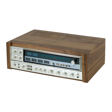
Sansui 6060 User manual

SERVICE
MANUAL
AM/FM
STEREO
RECEIVER
SANSUI
6060/5050
fou

This
service
manual
is
designed
for
service
engineers
to
repair,
adjust,
maintain
and
order
the
replacement
parts
of
the
5050,
6060
correctly.
When
ordering
the
parts,
use
the
stock
number
and
parts
name
speci-
fically
referring
to
the
Parts
Location
and
Parts
Lists.
For
general
usage
and
maintenance
of
the
unit,
please
refer
to
the
Operating
Instructions
attached
with
the
unit.
TABLE
OF
CONTENTS___...
Section
Title
Page
1.
SPECIFICATIONS
..............
0.
cece
cece
eee
tenet
eens
2
2.
BLOCK
DIAGRAM
..................
0.0
c
cece
cece
eee
eens
3
3.
ADJUSTMENTS
...........
Ula
daluih
at
auch,
ate
ePaaarciesS
wig
tren
avdiwm
Sate
teats
3
3-1.
Adjustment
of
Bias
Current
......-..-..+--+-
Bisciteace
ats
Gane
sttaea
thins
3
3-2.
FM
&
MPX
Adjustment
&
Alignment
...........-.+-ese
eens
4,5
3-3.
AM
IF
Adjustment
&
Tracking
.......-.:.ee
cece
eee
ee
eet
eee
6
4.
THREADING
OF
DIAL
CORD.................
0.
cece
eee
eee
ee
7
4-1.
Threading
of
Dial
Cord
..........
60sec
eee
e
cece
enter
nee
7
4-2.
Attachment
of
Dial
Pointer
..........
2...
eee
e
eee
eee
ees
7
5.
PARTS
LOCATION
AND
PARTS
LIST
..................-..-0055
8
5-1.
F-2648
Power
Supply
Circuit
Board
.........-
sere
eee
eee
eens
8
5-2.
F-26517
Illumination
Circuit
Board
........-..
eee
eee
eee
eee
9
5-3.
F-2650
Capacitor
Circuit
Board......
2.6...
cee
eee eee
eee
es
9
5-4.
F-2647
Driver
Circuit
Board
.........
26
cc
cee
eens
9
5-5.
F-2646
Tone
Control
Circuit
Board
........
faa
teachin
Acleties
ke
9
5-6.
F-2590
Tuner
Circuit
Board
.......
2...
cc
eee
cece
etna
10
5-7.
F-2645
Muting
Circuit
Board
.........--.
eee
eee
eee
eee
11
~~-~-5-8,
F-2644
Equalizer
Circuit
Board
.......
agra
oshanephewasyee
tay
11
5-9.
F-2649
Filter
Circuit
Board
.....
Mele
gtiya
dus
sor
eetone
ese
ties
aashadb
eae
11
5-10.
Figures
2.2.0.6.
cee
cece
cence
en
een
e
eee
n
nents
11
©
COMMON
PARTS
LIST
FOR
RESISTORS
&
CAPACITORS
ONLY
...............
00.
cece
cence
eee
(Attached)
6:-
OTHER:
PARTS
«060305050
dcce
vanessa
nade
ie
Sian
dee
enw
esea
dys
12
oy
a
Ko)
iS)
©
|<
12
622:
Bottom
Side:
«2s
5.4.6
eas
ee
hee
eae
ee
one,
ae
12
6-3.
Exploded
View
.......-.
ccc
e
cece
eter
eee
een
teenies
13
7.
SCHEMATIC
DIAGRAN...............-.----.
esse
eee
ater
tote
bein
sea
14
7-1.
MODEL
6060
ic.
iceberg
sree
noe
ek
ied
eka
eee
tee
asia
es
14
7-2:
MODEL.
5050:
iioc
indies
oh
keg
tg
eeene
tert
aie
ead
eee
Aaetans
15
7-3.
Semiconductors
.......--+.-.e0e-
sl
a
Ohad
5
abun
ease
es
ae
16
8.
OPERATION
BLOCK
DIAGRAM
................--
2
sere
eens
16
8-1.
Block
Diagram
of
Power
AMP.
&
Protector
Circuit
......----.
.
16
8-2.
Block
Diagram
of
Tuner
Section
....-+--++s+
eee
eres
Bice
dane
.
17
8-3.
PLL
Block
Diagram
(IC
HA1196).....-.-.-
220
e
eee
ee
eee
eens
17
8-4.
FM
IF
System
Block
Diagram
(IC
HA1137W)
...-----+--+
eee
ee
18
9..
PACKING.
EIST
3
o:..a0cckeccaetswac
cette
ieee
Bets
BACK
COVER
10.
ACCESSORY
PARTS
LIST
........................005.
BACK
COVER
1.
SPECIFICATIONS
AUDIO
SECTION
POWER
OUTPUT
MODEL
5050
Min.
RMS,
both
channels
driven,
from
20
to
20,000Hz,
with
no
more
than
0.5%
total
harmonic
distortion
30
watts
per
channel
into
8
ohms
33
watts
per
channel
into
4
ohms
Min.
RMS,
both
channels
drivan,
at
1,000Hz,
with
no
more
than
0.5%
total
harmonic
distortion
33
watts
per
channel
into
8
ohms
35
watts
per
channel
into
4
ohms
MODEL
6060
,
Min.
RMS,
both
channels
driven,
from
20
to
20,000Hz,
with
no
more
than
0.4%
total
harmonic
distortion
40
watts
per
channel
into
8
ohms
44
watts
per
channel
into
8
ohms
Min.
RMS,
both
channels
driven,
at_1,000Hz,
with
no
more
than
0.4%
total
harmonic
distortion
44
watts
per
channel
into
8
ohms
46
watts
per
channel
into
4
ohms
LOAD
IMPEDANCE
...........-
4,8
ohms
(SYSTEM
A
or
B)
8
ohms
(SYSTEM
A+B)
POWER
BANDWIDTH........--
20
to
20,000Hz
at
or
below
rated
min.
RMS
power
output
and
total
harmonic
distortion
TOTAL
HARMONIC
DISTORTION
MODEL
5050
...............05.
less
than
0.5%
at
or
below
,
rated
min.
RMS
power
output
MODEL
6060
..................
less
than
0.4%
at
or
below
rated
min.
RMS
power
output
INTERMODULATION
DISTORTION
(70Hz:7kHz=4:1
SMPTE
method)
MODEL
5050
.............0.005
less
than
0.5%
MODEL
6060
..................
less
than
0.4%
FREQUENCY
RESPONSE
(at
1
watt)
Pi
cdnnha
wt
cazeciet:
20
to
30,000Hz
+1.5dB
RIAA
CURVE
DEVIATION
(PHONO)
ney
eet
Serene
+1.0dB,
—1.0dB
(30Hz
to
15kHz)
DAMPING
FACTOR...
o+
~~.
approximately
45
at
8
ohm
load
INPUT
SENSITIVITY
AND
IMPEDANCE
(1
kHz,
for
rated
power
Output)
PHONO
ce
cccevevienbtee
eee:
2.5mV/50
kiloohms
(Max.
input
capability.
160mV
at
1kHz,
less
than
0.5%
total
harmonic
distortion.)
MIG?
cee
foieetiati
Ble
casc
2.5mV/50
kiloohms
TAPE
PLAY,
AUX
............
150mV/50
kiloohms
OUTPUT
LEVEL
(1;000Hz)
TAPE
REC
(pin
jacks)
........
150mV
TAPE
REC
(DIN
socket)
......
30mV
CHANNEL
SEPARATION
(at
rated
output
1,000Hz)
PHONO
fi
we
tea
weve
evea
ses
better
than
45dB
TAPE
PLAY,
AUX
............
better
than
45dB
HUM
AND
NOISE
PHONO
...........00.00
00s
better
than
70dB
TAPE
PLAY,
AUX
............
better
than
80dB
CONTROLS
MODEL
5050
BASS
ciao
caniia
icc
ndulh
+10dB
(50Hz)
TREBLE
co
iavucaeedsx
ear
eccees
+-10dB
(10kHz)
LOUDNESS
.............20005
+8dB
(50Hz)
+6dB
(10dB
(10kHz)
HIGH
FILTER
........--..-.-.
—10dB
(10kHz)
MODEL
6060
BAGG
eee
seo
unaadac
te.
+10dB
(50Hz)
TREBLE
isi.
c1c
ss:
es.0sa
We.dsrdes
Weise
eo
+10dB
(10kHz)
LOUDNESS
...........0
000
+8dB
(50Hz)
+6dB
(10kHz)
LOW
FILTER
..........-.0005
—10dB
(50Hz)
HIGH
FILTER
................
—10dB
(10kHz)
AUDIO
MUTING
............
—20dB
FM
SECTION
TUNING
RANGE
..............
88
to
108MHz
SENSITIVITY
MODEL
5050
EE)
soos
snes
11.2dBf
(2.02V)
z
(DIN)
voc.
eccccee
eee
ee
1.1nV
a
MODEL
6060
GHP
ceiatnn
snl
cbout
10.8dBF
(1.92V)
(DIN):
feseisn
eae
ca
LTV
50dB
QUIETING
SENSITIVITY
STEREO
(IHF)
.......ccsceeee:
38d
Bf
(452V)
MONO
(IHF)
.......0e00eeees
16dBf
(3.52V)
TOTAL
HARMONIC
DISTORTION
STEREO™
sccieciesn
viseccwe
alee
less
than
0.5%
MONO.
.......
00000
e
cece
less
than
0.4%
SIGNAL
TO
NOISE
RATIO
(mono)
stesshoac
des
tite
Aare
Setbdoa
bBtath
fs
better
than
65dB
-
SELECTIVITY
........00.cc0eeee
better
than
60dB
anes
CAPTURE
RATIO
.............-
less
than
2.2dB
IMAGE
RESPONSE
RATIO
(IHF).
.better
than
50dB
(98MHz)
IF
RESPONSE
RATIO
(IHF)
......
better
than
75dB
(98MHz)
SPURIOUS
RESPONSE
RATIO
(IHF)
wy
d
Seba
Toh
oschuataen
nereken’
better
than
70dB
(98MHz)
SPURIOUS
RADIATION
........
less
than
34dB
STEREO
SEPARATION
........-.
better
than
40dB
(1
kHz)
FREQUENCY
RESPONSE
........
30
to
15,000Hz
+}-°dB
ANTENNA
INPUT
{MPEDANCE..75Q
unbalanced
300
balanced
AM
SECTION
TUNING
RANGE
..............
535
to
1,605kHz
SENSITIVITY
(Bar
antenna)......
50dB/m
(1,000kHz)
SELECTIVITY
............000008
better
than
35dB
(1,000kHz)
IMAGE
RESPONSE
RATIO
(IHF).
.better
than
35dB
(1,000kHz)
IF
RESPONSE
RATIO
(IHF)
......
better
than
30dB
(1,000kHz)
OTHERS
MODEL
5050
POWER
REQUIREMENTS
POWER
VOLTAGE............
100,
120, 220,
240V
50/60Hz
120V
(Usable
110-130V)
60Hz
(for
U.S.A.
&
Canada
only)
.125
watts
(rated)
210
watts,
250VA
(max.)
POWER
CONSUMPTION
...
MODEL
6060
POWER
REQUIREMENTS
POWER
VOLTAGE............
100,
120,
220,
240V
50/60Hz
120V
(Usable
110-130V)
60Hz
(for
U.S.A.
&
Canada
only)
see”
.
.180
watts
(rated)
:
300
watts,
350VA
(max.)
POWER
CONSUMPTION
*Design
and
specifications
subject
to
change
without
notice
for
improvements.

TONE
CONTROL
CIRCUIT
F.2646
Ai:
Audio
Muting
SW
Tape
Monitor
SW
N.R.
Adaptor
SW
®)
High
Filter
SW
©)
<?
GN.R.
9
INPUT
L-CH
Selector
Balance
VR
(6060)
AUX
G
rREC
©
TAPE
€
PLAY
G
N
pout
iC
Mic
Jack
‘LIN
3.
ADJUSTMENTS
3-1.
Adjustment
of
Bias
Current
(See
Fig.
3-1
&
3-2)
eo
**
Audio
Muting
SW
%
Low
Filter
SW
|
not
included
in
#
5050
Relay
Pili
—o~e
5
Low
Filter
SW
L-CH
*
Speaker
Phone
Jack
(5050)
ee
ea
-——=
+40.5V
Driver
Circuit
Protection
Circuit
Board
EQ.
Tone
from
Pop
Noise
Circuit
SUPPLY
CIRCUIT
F-2648
LI
Regulated
Power
Supply
Tuner
Circuit
ts
—45V
Driver
Circuit
}—_—_——»
+
37V
(33V)
—37V
(33V)
)
shows
voltage
of
#5050
Power
Transistor
Value
in
(
ADJUST ADJUST
FOR
15mV
+1ImV
STEP
SUBJECT
EQUIPMENT
1
Bias
Current
DC
Volt
RO5,
ROZ
L-CH
Meter
F-2648
2
Bias
Current
DC
Volt
RO6,
RO8
R-CH
Meter
F-2648
Fig.
3-1
L-CH
®
®
® ®
15mV
+1mV
Fig.
3-2
Power
Transistors
(F-2648)
TRO1,
TRO2
Volt
Meter
®
:
RO7,
RO8
Volt
Meter
©
TRO3,
TRO4

eee,
3-2.
FM
&
MPX
Adjustment
&
Alignment
(See
Fig.
3-3
on
page
5)
Note:
1.
Selector
2.
FM
Muting
Switch
GENESCOPE
1)
FM
IF
Adjustment
&
Tracking
AUDIO
OSC
QO
TAPE
Oo
O
O
3.
Connection.
4.7kQ
IN
Sansui_|
dearbys
Connect
the
output
of
genescope
to
TP
through
100pF
ceramic
capacitor.
10pF
Q
DETECTOR
PROBE
BLOCK
FEED
SIGNAL
MEASURE
ADJUST
STEP
|
SUBJECT
FROM
7
|
OUTPUT
ADJUST
FOR
CONDITION
1.
|
IF
Coil
Output
60dB
TPO1
TPO3
TO1
Max.
IF
Genescope
F-2590
F-2590
F-2590
waveform
Use
Detector
Probe
2.
|
Discriminator
|
Output
50dB
Same
as
TPO4
Center
indication
Coil
Genescope
above
F-2590
on
tune
meter
TUNE
br
TO2
Max.
linearity
of
S
curve
Steep
linearity
of
*
S
curve
ir
T03
Set
output
wave
to
dip
point
(It’s
minimum
Wi
F-2590
|
distortion)
wi
3.
|
90MHz
|
99MHz
ANT
terminal
|
REC
OUT
LO3
Max.
Output
Dial
ANT
Input
60dB
3002
L
or
R-CH
+*F+2590
Calibration
400Hz
(100%
MOD)
VTVM
&
Scope
.
FM
SSG
106MHz
106MHz
;
Same
as
Same
as
above
|
TCO3
Same
as
above
Dial
ANT
Input
60dB
above
F-2590
Calibration
400Hz
(100%
MOD)
FM
SSG
4,
9OMHz
90MHz
Same
as
Same
as
above
|
L01,L02
|
Same
as
above
RE
Adi
ANT
Input
60dB
above
F-2590
J.
400Hz
(100%
MOD)
FM
SSG
106MHz
106MHz
Same
as
Same
as
above
|
TCO1
Same
as
above
RF
Adj.
ANT
Input
60dB
above
TCO2
400Hz
(100%
MOD)
F-2590
FM
SSG
5.
Signal
Meter
|
988MHz
Same
as
Signal
Meter
VRO2
4.3
on
Meter
Volume
ANT
Input
60dB
above
F-2590
400Hz
(100%
MOD)
FM
SSG

2)
MPX
Adjustment
FEED
SIGNAL
FROM
TO
98MHz
ANT
terminal}
Stereo
ANT
Input
60dB
3000
indicator
FM
SSG
Pilot
19kKHz
(10%
MOD)
L-CH
1kHz
(45%
MOD)
R-CH
(0%
MOD)
STEREO
SG
MEASURE
OUTPUT
STEP
SUBJECT
4.
|
PLL
VCO
Adj.
ADJUST
VROS5
F-2590
ADJUST
FOR
Light
indicator
CONDITION
Adjust
the
VR
within
center
of
lighting
level.
TPOS
F-2590
Use
Freq.
counter
PLL
Make
short
VCO
Adj.
between
In
case
of
TP04
&
using
Freq.
chassis
counter.
VRO5
F-2590
76kHz
+200Hz
For
this
adjustment,
run
the
unit
over
30
seconds.
ANT
terminal]
REC
OUT
L-CH
VTVM&
Scope
98MHz
ANT
Input
60dB
3002
FM
SSG
Pilot
19kHz
(10%
MOD)
L-CH
(0%
MOD)
R-CH
1kHz
(45%
MOD)
STEREO
SG
2.
|
Separation
VRO4
F-2590
Min.
Output
—35dB
Confirm
separation
L-CH->R-CH
—35dB
Stereo
indicator
Same
as
above
3.
Muting
98MHz
level
&
ANT
Input
23dB
indicator
FM
SSG
level
Pilot
19kHz
(10%
MOD)
L-CH
1kHz
(45%
MOD)
R-CH
(0%
MOD)
STEREO
SG
Adjusting
or
Connecting
Points
on
AM,
FM
&
FM
MPX
circuit
board,
F-2590
Fig.
3-3
a
$01
TO3
!
a
)
ey
é
VRO2
VRO3
O
TPOS
VROS
CFO4
VRO3
F-2590
Muting
level
23dB
Indicator
lighting
level
23dB

“4
|
|
|
t
3-3.
AM
IF
Adjustment
&
Tracking
(See
Fig.
3-3
page
5)
Note:
Selector.
.
2.
Confirm
start
point
of
dial
pointer
before
alignment.
FEED
SIGNAL
MEASURE
ADJUST
STEP
SUBJECT
FROM
7
|
OUTPUT
ADJUST
FOR
CONDITION
1.
IF
Coil
Genescope
TCO4
TP06 CF04
Max.
IF
Output
65dB
F-2590 F-2590
F-2590
waveform
2.
|
600kHz
600kHz
AM
ANT
REC
OUT
T-04
Max.
Output
Dial
ANT
Input
60dB
terminal
L
or
R-CH
F-2590
Calibration
|
400Hz
(MOD
30%)
VTVM
&
Scope}
.V.
AM
SSG
Tae
1400kHz
1400kHz
Same
as
Same
as
above
}
TC05
Same
as
above
-
Dial
ANT
Input
60dB
above
F-2590
ae
|
Calibration
400Hz
(MOD
30%)
AM
SSG
3.
|
600kHz
600kHz
Same
as
Same
as
above
|
L702
Same
as
above
RF
Adj.
ANT
Input
60dB
above
Bar
400Hz
(MOD
30%)
Antenna
AM
SSG
|
1400kHz
1400kHz
Same
as
Same
as
above
|
TC04
Same
as
above
RF
Adj.
ANT
Input
60dB
above
F-2590
:
400Hz
(MOD
30%)
AM
SSG
4.
|
Signal
Meter
|
1000kHz
Same
as
Signal
Meter
VRO6
4
on
meter
volume
ANT
Input
54dB
adove
F-2590
400Hz
(MOD
30%)
AM
SSG
Abbreviations
Epuipment
Others
AM
FM
Generator
O&cithoscope............
Genescope
Clockwise
o..:
sees
cece
cece
ee
eee
eect
e
eens
CW.
AM
Standard
Signal
Generator
............
AM
SSG
Counterclockwise
...........0.
cece
eee
eee
eee
CCW
FM
Standard
Signal
Generator
.......-.-..
FM
SSG
ANt@nhia®
ss
Scien
wseernds
tare
eee
eis
ed
ANT.
FM
Stereo
Generator.............-.020005:
Stereo
SG
Modulation
...........0ccceccce
eee
eeeeteeeeas
MOD.
Oscilloscope
6.0...
0...
c
eee
cee eee
ee
eee
Scope
Audio
Oscillator
..............
00.200
eee
Audio
Osc.
Distortion
Meter
..........-...
ee ee
eee eee
Dist.
Meter

4.
THREADING
OF
DIAL
CORD
*If
a
dial
cord
is
cut
off
or
slips,
replace
it
by
following
procedures.
As
this
unit
uses
0.6mmé¢
cord,
please
replace
it
with
the
same
type
certainly.
*The
length
of
dial
cord
is
approximately
160cm
(65.3
inch).
FM
‘AM’
535.
600
Fig.
4-2
4-1.
Threading
of
Dial
Cord
Thread
the
dial
cord
in
numerical
order
from
@®
to
as
Fig.
4-1.
Seen
ras:
1)
Close
the
variable
capacitor
completely
(Max.
capa-
citance).
2)
Tie
dial
cord
to
the
screw
S1
of
the
dial
pulley.
3)
Thread
cord
in
the
direction
of
arrow
from
@
to
@.
4)
After
@,
tie
the
cord
to
the
screw
$2
of
the
dial
pulley.
4-2.
Attachment
of
Dial
Pointer
1)
Close
the
variable
capacitor
completely.
2)
Set
the.dial
pointer
as
Fig.
4-2.
—
*Confirm
that
the
dial
pointer
runs
smoothly
on
the
dial
scale
by
turning
the
tuning
shaft.
Parts
List
Stock
No.
Description
6036050
Dial
Cord
(0.6mm¢)
6146663
D35
Type
Pulley

2
5
6°
a
a
o
Boe
a
o
27%
<<
o
oF
<<
au)
a-
oa
99
a
aa
o9
BE
°
eo
~
2.5
O55
£
§
Oo
.F
<
af
a
8
aa
3
2
ped
e
i
2
68
5
~
&
22
6
.
sz:
g
-£
a
>
<
IG
ow
6
[Ge
Bz
ee
22
Zod
Peed
=
Sas
>
es)
+S
aa
oy
ag
“ae
-“~nn
GG
gs
=~S8n
GG
SN
[S)
Otc
oo
Qaoct
oo
OounYy
Ags
oo
<<
anu
ao
g<
ener
Stee
NNW
o-
wT
NAW
=
ow
NOs
.
led
AAR
05
Z2/Z-<s
ss
ee
Sense
sc
o°
ce
x/oss3
22
88
68385
22
88
383
§)/8888
88
$2
8888
88
88
a5o288
ao
geese
859
66
£838
88
8368
3
4Zus
=
—
—-Oo0r7
scliag
Gay
J
al
8
83
Seog
z
On
ss
Onna
>
ag
hu
2#/Os2e
$2
g3
9282
82
98
s
&
8
Fl)
eRRrr
a@e2
£2
FFFF
2&2
Be
a
j=
&
(e)
re)
=r
2
UsU
9 3
sh
:
noted
s
_
ateqcqec
ote
ce
MYGaotcyv
5;
VU
<
—
ss
é
OANA
Andadkaaae
a
”
oo
ome
Ye)
oul
NN
ae
oo
<
GP
ZZ
:
ee
©
G
5
Ue
:
oe
a
aman
Oe
Sig
4
8
65
Xe
2
Ss
F
~~
s
UHH
isoiee®
SOX
soi
mre OO!
4/9
Vv
2
0
VYVF
*
OU
ot
anita
VY
BUR
i
m
$e
Qu
o
2
o°9
pustinaapexalaaaties
:
flea
cee”
5
>
3
eaegad
SeESES
2
>
oe
j
7
giz
8
22
222
5
3
Ge
gues
wwe
ipaspaensecs
iss
Us
a|~-
5
x
a
“Xa
Ko
S$
tpSa>
tiie
eteds
BE
——_——_
-—
——
_—
5
=
8338
oO
iearanmnaneteresneionesen
ba
saaRE
GAacaaacaga
§
&
BXEK<<
TE
ERE
ged)
i
sseess
sagannedss
9
2
Sedeer
i
ose
i
ee
seeee
woRtet~
Rann
bs
F
Naeger
.
?
ONS
Bes
o7)
tts
oo
=
Oo
facan
o~]
;
|
CE
RRE
264
im
+
mc
£
AVES
S
a)
oe
PRSLSD
P
gases
AY
7
q
-}
O
=
e/RESSE
SSGSSSRRRH
§
2
SHER
S{/FSBB8R
KKASSSssegs
fF
B&
FLRSES
Ld
gi/Se23o
ZF2RBR22ER222
8
2
SESeE
om
%!GC5055
SSESEESESSSS
+
=
GANANNN
<x
ape
Y
2
wigvein:
“S38
SRE
ee
a
SO
gh
oo
oS
=
3.35
Ss
za_sa
ee
4
5355
2228823333
3
2
3
[SRE
tres
a
oO
UO
J
28s
ETE
eI1O
~~
S126
=
cane
£|3
@
|
os
<
!
—_
a.
£/<2000
aeVUVHeacKeeeXZE
qe
VOL
oman
a.
AMIAAMD
MMM
MMMMNMAANAMN
BAW
MMO
MO
{
x
5s
a
oO”
:
"
.
3
i
2
2,
‘
in
8
2
a
J
o
ae
z|
2
;
:
0
1
3
ae
fog
H
2
ro]
A}e33uu
=
OPRR
8
ep)
a.
Pay
eC
RC
creer
3
3
e238
o¢te
=Z322
ge8
g
F3
355
esses
1
uv
NA
oS
a
ez
SOO8B
BEG
o
o
6683
S855
'
=
ANnNWNN
GAG
fay
3
nog
VT
‘
r+?
=
8
os
sl
ananan
a
'
S
Zlaz--nnNn
OSDO959D009909099
S829
AnNNN
4
As
zw]
ORnMan
BAARHHHHHDNRNHND
RRD
RRAKR
4
oe
o/h
A&E
OM
SeSIOaanmnanagnnn
ons
tyr
+
1
I
°
ow)
wo
2
oO
ecoooooc
of
--
ownn
ow)
4
3
S|/88888
SSS8RS888R288R88
BBS
BB88
1
a.
bie
rd
"18Sesse8
Sssesessssssss
Ses
$8SS
'
eo
Par
oe
388
:
33
=
ave
$88
axzne
a
lal
e|eSSEE
FTFESSSSSSSESER
BSA
BFBB
Ww
:
Ble
FEFFE
BARgAGbG4G464
NNN
SSG
Lf)
ale
LN
FA

i
1
i
i
1
i
°
e
. e
(Stock
No.
7594161
MODEL
5050)
-
5-2.
F-2651
Ilumination
Circuit
Board
(tock
No.
7594111,
MODEL
6060)
Parts
List
Conductor
Side
(Ga
eee
Oe
1
eS
a)
Gorltecde
ee
—
poeenes
SUAS
ER
Sos Raa
Poo
ots
oe
3
eindasicrnnd™
4
i
|
i
3
ne
3
ps
Goo
34
4
Ee
ea
io
Ht
naan
Parts
No.
Stock
No.
Description
Deo
0310340.
.10D-1__
Diode
Ceo
0501331
.-
330¢F
10V
EC.
Reo
o19t160
18D
YW
Fuse
R.
°
°
°
(Stock
No.
7501681
MODEL
5050)
5-3.
F-2650
Capacitor
Circuit
Board
(6ck
no.
7501711
MODEL
6060)
Parts
List
89-50
SANSUI
mie.
sans
©
° .
°
(Stock
No.
7571421
MODEL
5050)
Conductor
Side
ee
ee
Parts
No.
Stock
No.
Description
MODEL
5050
Only.
Cais
0549112
4700
pF
C20
0549112
peed
SON
SEC.
MODEL
6060
Only
Cais
0549111
“6800
pF
Ce2
O54911T
6800
et
sO
LEG
Parts
List
Parts
No.
Stock
No.
Description
Position
TRo1,02
0300470,1
2SA726
(W)
FG
1A.1C
TRo3,
04°.
.0300470,
1
2SA726
(W)
F.G
1A.1C
TRos,06
0306360,1
25C1951-1,-2
Transistor
=
1A.1C
TRo7,08
0308521,2
250438
E,F
2A.2C
TRog,
10
0303361,2
258560
E,F
2A.2C°
ZDeor
0315970
EQA01-13R
“Zener
Diode
1B
Ra1,32
0193221
2200)
,
2A.2C
Rss,
34
(0193221
pant
”AW
fee
k:
2A.2C
VRoi.02
1035310
1kQ
(8)
1A.1C
EEE
F
F
(Stock
No.
7561471
MODEL
5050)
5-5.
F-2646
Tone
Control
Circuit
Board
(ocx
No.
7561491
MODEL
6060)
Conductor
Side
Parts
List
Parte
No.
Stock
No.
Description
Position
Parts
No.
Stock
No.
Description
Position
TRot,c2
0306070,1
2SCINSAG
|,
=
CoB
VRos
—-1015180,1
100k.
Bx2
B
TRes,o4
0306070,1
2SC1313
FG
J
BLA
VRos
1015180,
1
..
100k
Bx
2
A
Cor.o2
0620331
330pF
SOV
PAC,
D.C
Sos.
1131110)
:
D
Sos
131290)
Push
Switch
A
Reor
0193221
©2200
Fuser.
B
!
VRor
=—-1015190,1
10062
M.N
c.B
MODEL
5050
Only
VRo2
-—«-1010920,1
250k
2
x2
D.C
Czs,24
0600127
0.012#F
=SOV
MC.
*
Parts
No.
Rss,
54
Stock
No.
MODEL
6060
Only
Ras,
46
Raz,
48
Ras,
50
Sos
Description
Position
0240824
82002
Ww
CR
A
0240392
_
3.9kQ
A
0240393
39kQ
DYW
CR.
A
0240222
2.2kQ
A
Push
Switch
1131300
9
oe

°
°
Stock
No.
7521321
MODEL
5050)
-
>
5-6.
F-2590
Tuner
Circuit
Board
(0%
No
ss21091
MoDut
cos,
Conductor
Side
Parts
List
Ls
Parts
No.
Stock
No.
Description
Position
Parts
No.
Stock
No.
Description
Position
Parts
No.
Stock
No.
Description
Position
)
TRor
0305801
2SC1047
(B)
2A
Cor
0669350
15pF
3A
Tos
4290280
Inductor
Fs
TRo2
0305801
=
28C1047
(B)
2A
Cos
0659015
2200PF
wy oc
2A
Tos
4290011
Choke
Coil
TRoa
0306113
~~
28C738
(D)
1A
Cor
0669350
15pF
aS,
3A
TRoa
0306112
=
28C738
(CG).
4
1B
cu
0669355
20
pF
2A
CFo1
0910150
=
10.7MHz
1A
TRos
0305731,2
2SC711
(EF)
aa
3c
Ci2
0679012
1.5pF
500V
G.C.
aed
are
CFo2
0910160
10.7MHz
rilney:
1A
TRoe
0305731,2
2SC711
(E,
F)
1B
Cas
0629005
360
pF
2c
CFo3
0910150
=
10.7MHz
1B
TRo7
0305731,2
2SC711
(E,
F)
:
2B
C4s,49
0620101
100
=)
50V
P.C.
1c
CFos
0910280
9
455kHz
2.38
TRos
0305731,2
2SC711
(E.F)
f
Transistor
18
Cso,51
0620561
560
pF
TRo
0300470
=.
2SA726@
(F)
2A
Cor
0669400
15pF
50V
C.C.
28
LFo1
0910220
=
19kHz
Low
Pass
Filter
TRio.
1
\psrese
28C735
(Y)
3c
Cos
0620361
360pF
S50V
P.C.
i
0306390
=.
2SC
1636-1
VRo2
1035170
47kQ
(8)
2B
TRi2
0300283
=.
2SA626
(F)
38
Lo
4200720
Antenna
Coil
3A
VRo3
1035190
100kQ
(B)
28
TRis
0305731,
2
28C711
(E,F)
Loz
4210340
RF
Coil
3A
VRos
1035210
220k2
(8)
1
TRis
0300510,1
2SA733
(P,Q)
Los
4220400
OSC
Coil
2A
VRos
1034250
4.7kQ
(8)
2c
Los
4290110
Choke
Coil
2A
VRos
1035110
ICo1
0360350
=
IC
_HA1137
(W)
1B
Loz
4900100
3B
1Co2
0360320
=
IC
HAI196
Ic
1c
Los
4900100
2B
Sor
1110270
Slide
Switch
ICos
0360150
IC
HA-1151
3B
Los
4900220
>
Inductor
3c
:
Lio
4900110
38
VCo1
1220250
Variable
Copacitor
2A
FTo1
0370131,2
3SK41
(1)
(L,K)
FET
lu
4900110
3B
TCoa
1230090
Trimmer
Capacitor
Dor
0340120
VDI212
=
Varistor
28
Tor
4235930
IF
Coil
1A
.
2410600
6P
Pin
Ass'y
Type
D
Do2
0310330.1
INé60
Diode
3c
Toz
4235970
Cai
2B,C
2410910
2P
Pin
Ass'y
Type
E
Do3
0340120
VD1212
=‘
Varistor
28
Tos
4235980
FM
Coil
2B,C
2410920
3P
Pin
Ass'y
Type
E
Dos
0311160
=:
1$2473D
Tos
4220650
=
OSC
Coil
3B
—
$$
10

a
2
Ee
Shae
tt
ea
Haile
tb
ge
act
at
She
RS
eG
eS
ied
a
de
ara
ee
ie
ge
a
iy
i
Re
cetera
amet
oe
ARS
es
ELT
Se
in
Bae
ot
Ratna
ae
Ste
mr
Ra
te
ee
ee
e
°
e
(Stock
No.
7594151
MODEL
5050)
5-7.
F-2645
Muting
Circuit
Board
(Stock
No.
7594101
MODEL
6060)
aS
Conductor
Side
Parts
List
{
ParteNo.
Stock
No.
Description
Sor
1331320
Push
Switch
°
°
°
|
(Stock
No.
7550941
MODEL
5050)
5-8.
F-2644
Equalizer
Circuit
Board
(¢.5ck
No.
7550961
MODEL
6060)
Conductor
Side
:
Parts
List
A
B
C
PartsNo.
Stock
No.
‘
Description
7
Position
:
TRo1,02
0306070,1
3SC1313
FG
2A.1A
=
TRo3,04
0306070,1
2SC1313
F.G
|
oan
2A.1A
TR6o1
0306070,1
28C1313
F.G
j
tonsistor
26
TReoz
0306070,1
2SC1313
FG
2c
Co1,02
0573339
3.3uF
35V
TLC.
2A.1A
Cos,05
0625103
10000
pF
2A.1A
Cor,08
0625272
pal
SOV
EG,
2B.18
Csoz
«0873339
3.3uF
35V
TLC.
2c
Ris,16
0231394
=
390k.
2A.1A
Ri7,18
0231273
27k}
WW
MR
2A.1A
i
Reo
0200221
2202
1B
2410920
3P
pin
Ass’y
Type
E
2410930
4P
Pin
Ass'y
Type
E
!
—
oy
|
ee
i
=
e
e e
5-9.
F-2649
Filter
Circuit
Board
(stock
No.
7561501
MODEL
6060
Only)
Conductor
Side
{
e
|
5-10.
Figures
i
Connector
&
Pin
Ass’y
Connector
Pin
Ass'y
Type
A
(3~10
pins)
Type
B
(2~6
pins)
Stock
No.
Type
A
(3~10
pins)
Type
B(3~10pins)]
Type
C(3~10
pins)
2Pins
2420450
3
Pins
2420460
3
Pins(RE0)
2420650
4
Pins
2420470
5
Pins
2420480
6
Pins
2420490
NOTE:
Since
stock
number
of
famale
connectors
(type
B)
with
wires
are
not
Type
D
(2~6
pins)
shown
in
each
parts
list
of
Complete
circuit
board,
please
refer
to
the
above
parts
list
when
ordering
the
connector.
Abbreviations
c.R.
:
Carbon
Resistor
BP.E.C.:
Bi-Polar
Electrolytic
se
7
\
S.R.
_:
Solid
Resistor
Capacitor
'
{
Ce.R.
:
Cement
Resistor
c.C.
=;
Ceramic
Capacitor
M.R.
+:
Metallized
Film
Mi.c.
:
Mica
Capacitor
Resistor
o.c.
:
Oit
Capacitor
M.Cc.
:
Mylar
Capacitor
P.C.
:
Polystyrene
Capacitor
E.c.
:
Electrolytic
Capacitor
E.c.
:
Tantalum
Capacitor
11
\

6.
OTHER
PARTS
|
6-1.
Top
Side
Bar
Antenna
Holder
Voltage
Selector
Bar
Antenna
|
Bar
Antenna
Holder
Case
eae
Antenna
Terminal
R707
PTo1
oy
;
C704.
2
;
i
|
r
6-2.
Bottom
Side
aoe:
4
4P
Input
4P
Terminal
4P
Output
4
S
ath
Terminal
Terminal
AC
Outlet
Power
Cord
Ground
Terminal————
AC
Fuse
AC
Fuse
Holder
|
C701~C703-
)
C705
i
|
|
DIN
Jack
.
R701~R704
|
Parts
List
(Top
Side
&
Bottom
Side)
Parte
No.
Stock
No.
Description
i
Parte
No.
Stock
No.
Description
.
Parts
No.
Stock
No.
Description
C7o1~703
0657473
4700pF
50V
C.C.
J703
2430041
DIN
Jock
2310030
P
Type
Fuse
Holder
1
C74
=
0605337
0.033
xF
250V
MAC.
F
;
2410091
—_P
Voltage
Selector
Plug
C7s
«0659802
«0.0047
uF
150V
C.C.
a)
\iasaee
a
Ganjeawy
2410830
—_‘10P
Voltage
Selector
Socket
7
Rror,
702
0240104
ena
YW
CR
0432270
5A
250V
(100/120¥)
}
MODEL
6060
3800010
Power
Cord
Pores
\
R703,
704
0240334
3300!
4
AR.
0432240
2A
250V
(220/240V)
3910490
Strain
Relief
a
t
R705,
706
0163221
2200
3W
Cor.
0432280
4A
128V
(100/120V)
}
MODEL
5050
5266442
Bor
Antenna
Holder
‘
oat
Rro7
0103122
1.2kQ
BW
CR
2200320
4?
Terminal
5287280
Sar
Antenne
Holder
Case
'
R7oa
0240322
1.2kQ
Ww
CR
2210310
Antenne
Terminal
PTo1
4002460
Power
Transformer
(MODEL
6060)
Loz 4200830
Bar
Antenne
parted
>
paeperamy
4002470
Power
Transformer
(MODER
5050)
'
COv7o1.702
2450060
AC
Outlet
2300060
=
Fuse
Holder

Sete
A
ae
ee
tt
ange
ey
6-3.
Exploded
View
Parts
List’
Parts
Stock
No.
Description
1
5727020
Wood
Bonnet
(MODEL
5050)
5727010
Wood
Bonnet
(MODEL
6060)
2
+
5318380
M-7
Type
Knob
3
5318410
S-10
Type
Knob
4
5318721
E-13
Type
Knob
5
5326550
Push
Knob
(B)
&
5326580
Push
Knob
(C)
7
5318420
=
T-12
Type
Knob
8
5304880
‘Front
Panel
(MODEL
5050)
5304850
—
Front
Panel
(MODEL
6060)
9
5304840
Panel
Window
10
=
5286721
Knob
Guide
_1__
Sree
Description
Farts
Stoo
k
Desctintion
Farts
Steck
Description
5446291
Smoked
Plate
(MODEL
5050)
21
=
1131320
Push
Switch
}
33
0400200
_Dial
Pointer
Lamp,
6.3V
75mA
5446281
Smoked
Plate
(MODEL
6060)
22
1010920,1
Volume,
250k.
Bx
2
34
5416050
Dial
Pointer
1101470
—
Speokers
Switch
23
5393300
Masking
Ring
35
§408090
Dial
Glass
1131190
Power
Switch
24
7036491
—
Tuning
Unit
Ass'y
36
0400450
FM
STEREO
Lomp,
7V
100mA
2430190
Head
Phone
Jack
25
1131310
|
MODE,
LOUDNESS
Switch
37
5058270
_
Illumination
Box
6906480
Spring
26
1005170.1
20k,
MIC
Volume
38
0420040
Meter
Lamp,
7V
320mA
5326530
Push
Knob
27
=
2430170)
=
MIC
Jack
39
5288130
Meter
Holder
1131490
fet
Filter
Switch
(MODEL
5050)
28
1102690,
1
Selector
40
6146663
35
Type
Pulley
Audio
Muting
Switch
(MODEL
6060)
29
4301000
Signal
Meter
41
=
7136082
—
Tension
Unit
1131300
Low,
High
Filter
Switch
(MODEL
6060)
30
4300990
=
Tune
Meter
42
5516821
—
Leg
1015180,
1
Tone
Control
Volume,
100kQ
Bx
2
31°
5416350
Holder,
Dial
Pointer
43°
5058651
Bottom
Plate
1015190,
1
Bolance
Volume,
100kQ
M.N
32
5516030
‘Teflon
Sheet
SS
13

vi
i=
7
o
~
uy
uj
=
f
&
a
ee
i
pe
a
ee
ae
TN
8
wu
i
GN
gg
r=
.
rT}
+
@o
a
cence
i
8
a
tel
o
gS
x
oF
an
=
=
a
&
‘
Sq
'
iS
0
o
'
=
P)
9
a
n
3
Shy
@
|&>
¢
1
WR'9
Hy
ATMO
7D
sery
yess
—yiby
Ed
&
2
pt
:
&
we
a
+g!
57
By
5
ra)
‘
N
'
ASE
-
r
&
IR
lek
+
'
2
=
aH
18
80
!
Agere
Sys
R<
5D
gy
Sy
a
On
|:
Ss
ft
We
rr
Mm
|S
w
a
‘
+
a
J
=
“OR
]e
mh
&
————
&
'
u
<
oO
1
°
oy
8
}.
'
1900
'%
ay
09
|
a
Aw
ao
NS
ou
~
ay
41
+
——
s6
eG
an
vt
we
v,
aes'y
é
t
|
faa
fT
ia
Oa
ee
=
ny
Rs
|
SS
7
;
1
H
=
;
ou
ta
oO
[2
ey
yey
|
a}!
!
xf
(E7022
Sty
a
=
u]
8
se
ee
ee
Nt
epi
F
gk
&
ee
tN
Se
a
&
2
try
S|
©
1
T
Td.
$
1
s
°)
@--
3d
b
;
lad?
&
4
3
Sr]
on
%
5
'
4
sg
Md
2
30
aay
soe
1
iN
S
3
x
ht
a
_
Re
partes’
asetigo+
qu
Kd
'
Nes
td
is
BAS
e
tis
CS
:
‘
:
+4
2
w=
Baty
a
16
sf
own
2t5
*
yay
sy
—
4
8
|
\
a
AW
HEE
My
Nae
y
.
=
§
id
m
-
a
Ra
3
,
if
é
t——*
{
=
N
499
HY
409
2
6
H
gan
yee
My
:
=
3
&
ke
laa
R
ae
a
a
<
es
%
;
g
:
Py
7
¢
%
&
&
sy
2.
!
20
7
—
+4
Fe
=
xX
SN
8
3°
aa
al
os
S
as
won
4s
t=
COS
yee
a
la
My
sR
tht
(c)
Meg
2a5y
§
Fo
uw
N
7)
lw
N
a)
-~
2
4]
$
ko
69
A
er
1
i
3
a
S
m
g
|
B
10g
rooes
wl
m-
’
=
:
9
an
a
8
ss
~
a
uN
Oo
HOEY
'
ae
tent
1
8G
289
BR
one
Sy
)
|
rs
f
'
:
(
o-
aR
200%
a
ae
5
Sis
8
ry
a
Sse
2O
=
q
ge
Soe
es
ft
bf
=
2
NSS
7
:
1&O
&
§ 8
Ca
=
.
@
ie
int
4
w
Ww
>
dy
—
>
s
3
BS Rn
iad
We
Sui
1X
|
cs
B
8
x}
8
S|
#883
BsSess
a
&
at
19
IA
x
Pers
B-arino
H
8
9
cone
,
3
gus
&
&&
<
t
3
tt
|
rs
88g
d02HS
"9
rc}
ee
tae.
Be
AS
ta
OS
a
<~“
200")
uw
4
gS
Ss
o
d
s
é
3
se
8
Kk
i
WEE
=
@
3s
$
8
3
®@
Ss
FA
D
osbe
3
5
8
os
“9
7
1
es
8
Eo
3
|
ot
te
g..
cd
§
«Z2R
Sea
Sou
Su
:
z S
|
g2Ss<
SSS<eche
Wowuer
Suz
;
s
g
SHEEE
LIEGE
IS
SyHESSSSSS
&
|
RY
st
wee
—
se
sgav8
“Nes
z
+
cH
]
iS
S
§
|
ug
9
BB
=
-+—_—_-
vT
é
SN
1
|r
|
588
pad
Pas
|
3
a
:
3
a
—=
Sa
$
a7
é
g
L900
'%
PHONO
I
Caley
ny
g
752
3
E
EU
MODEL
ONLY
“sjuawanosdut
40}
931}0U
JOYA
aBueyd
Oj
JDalqns
voNediyi9ads
pue
ustsag
.
A
0
“US}EYSq
JOA
Vagis|g
‘UBUBIP
331449S]104
UaYyIS!UYI9}
Wap
op
‘UeBuNiapuy
.
:
SalaNIUsA?
SUONeJO!/9WE,p
BJINS
Jed
SiAegId
SUES
SAgIpPOW
1249,p
serqndeosns
Juos
suo!}eD}j199dS
Sa]
12
UONeJUasOId
e1,

—_
“spjyonqueAg
SUOT}es0)/9LUE,
sere
an
Ss
fo
-
fs
© >
gas:
eee,
Ra
=
ES
SS
af
=
a
c
§
«
wi]
&
ozetty
|
ozeey|
y
Se.
a
=
®
1
8
Q4)
a
“
5
>
;
.
Z
2
8v92-4
Ss
>
S
.
%
"
3
=
7
is
22
2
8
x
491
BY
s
slael
&
a
80
<
fae
&
RS
Ey
|
=
¢
:
é
Se
é
Y|
=
4
3
5
ne
ees
36
Nu
S
7)
,
wrk
io
ra
4
ceky
yeeyT
28
|
5
=
/h
r
91
84
FES
”
g
4
Ro
rr
S
w
Rg
hed
~
=
6
es
8g
fe
e
A
(6022
ey
w
&
3g
|
lexaze
my
g
N
~
nN
=
+
~AAN
a
1
Sk
=
3
:
'
N
Eg
a
_
§
Low
°
a7]
o
g
“at
-_
eS
I
a
ie
g
Aste
AS
&
5
3
|
N
Ray
bel
Cy
(nag
ogre
‘
4
3
g
469
1
?
N
&
ae
Bit
Sy
ks
ose
[22000
5
4
ALPHIED
[dee
&
~
oi
ola
89
weEry Neoty
aye
ae
P
$
8
se
eOF
‘
=
©)
BRS
bs)
S
3
ar
i
SS
128
tye
(M2)
a
ao
3
;
028
€
ys
oh
5
a
3
a
8
|
3
:
7
=
5
ie
5
Fy
x
van
wl
4s
T
&
a
Y
r
a
x|
&
oy
g
2200
wosi>
12]
Ss
<
a
Se
Wee
ml}
=
<
s=
hath
f
4
Q
9)
3
3
Te
‘OS
gS
fe
a
|
3
i
g
3
ss
al
|
7
3
ie
3
19
N05
"he
8
|
g
has
8
B
2
z
4
r
~
1
-§
s
0g
bb
~
ms
ia
S
u
‘
o
w
oO
g
-
|
&
x
It
©
9
rs)
“ 3
N
Ol
a
}
ny
rs
a
af
8
r
[s
:
x
a:
i
BS
1g
i
x
:
220029
oF
ia
y
Q
004
1
raed
Sag
é
~
7
&
3
:
8
1
39
&
Uf
oa
an
so
&
-
*
a
“8
g
i
stie
GB
:
Oo
ez?
SSS
|
3
uit
@
oe
wv
Her
ang
Zi
pMnego
w
id
3,
Febote
>
usy
3
&
ESS
20000,
SOguy
3
as
Sai
Besind
Ye
S~
|
3
>
=
&
zag
jase
§
|
i
g&
moss
Zs
Oxn
¥g
8
3
ss
CU
|
a
sz
x
4
ie
1£
333733
%
sn
y
433
q
8
‘i
i:
8
8
&§
8
86
&
&
|
8
:
2a
Ss
5.
°
:
e98
E888,
fou,
S
ess
xESEEb,
GSBu
Bhs
3
¢
3
88
SEeEETSS
Sag
SE
BEUSEES
w
o
:
g&
Se
ans
quill
ing
ean
VO“
a
hed
SS
racy
ze
“S""S
"8
=
é
‘
ea
2
=
ap
a
#
As
aie
——
Hit
40699
(%)
va
err,
I
ZZ
a
8
&
3002
=
&
‘sjuaWangidul!
JOy
BDIIOU
INEYTIM
BBueYs
0}
joaiqns
u0}jeo1j198ds
pue
UBISEg
«
“ya}/eyaqsoa
Usqta|q
"Uaualp
32/449S7204
UaYyos!UYyIaI
Wap
a1p
‘vazUNIEpLY
»
Pp
ajins
ed
siAegad
sues
sagijIpow
43}9,P
sa1qiidaosns
yUuOs
sud!ze9/j1990S
$9]
18
uoljezuasgud
2],

i
!
|
!
if
|
!
2SA733
2SB560
28C945
2801047
28C1364
28C1951
2SD438
ECB
28C1636
ECB
Circuit
%&
This
Protection
(Relay)
Circuit
serves
to
protect
spea-
kers
when
DC
voltage
appears
at
output
of
power
amplifier
stage,
resulting
in
relay
being
released.
When
the
DC
voltage
exceeds
2.5V,
the
arrows
$f
well,
Differentia
Amplifier
Value
in
(
7-3.
Semiconductor
2SA628
2SA726
28C711
280738
28C1313
BCE
2SA765
2801445
2SD188
NF
3B;
Loop
Gu
Driver
)
shows
voltage
28C735
HA1151
1
Hisr,
98
HA1137W
HA1196
i
3458
4
109
8
F-2647
POWER
AMP.
Driver
Tr.
jas
rrent
VR
Tr.
Driver
Tr.
of
#5050
—45A
182473D
EQA01-13R
EQAO1.24R
EQAQ1.25
at
VD-1212
or
DS-430
30D-2--.
*
8.
OPERATION
BLOCK
DIAGRAM
8-1.
Block
Diagram
of
Power
AMP.
&
Protector
Circuit
~F-2648
PROTECTOR
CIRCUIT
ae
Phase
cr
i
|
+
Compansation
RL601
L-CH
OUTPUT
To
Speaker
—37V
(—33V)*
R-CH
,
eae
Amp.
R-CH
Speaker
(Relay)
-
show
the
variation
of
voltage
drop
or
increase.
When
the
DC
voltage
drops
below
—2.5V,
the
arrows
&
f
show
the
variation
of
voltage
drop
or
increase
as

cy
BLOCK
DIAGRAM
ee
Lona]
|
Tune
Meter
Discriminator
Out
MPX
PLLIC
xs
)
:
J
rat
HAIG
>
Byes
+B
(AM)
(Muting)
——+/2V
LOW
PASS
FILTER
FM
Signal
Meter
VR
Muting
&
Indicator
Adjust
VR
Signal
Meter
™
xz
+
.
Just
tuning
OV-----OFF
AM
TUNER
Tuning
off
R-CHY
1-H
r
[771
0.6V----ON
,
Muting
SW
x
—
Vy
FM
FM
DOLBY
AM
Signal
Meter
OUT
ADAPTOR
R
SELECTOR
a
MUTING
&
INDICATOR
CIRC
8-3.
PLL
Block
Diagram
(IC
HA1196)
PLL
BLOCK
DIAGRAM
(IC
HA1196)
¥
Free
run
freq.
{
adjust
volume(76kHz)
Stereo
or
Mono
Switching
Signal}
~--
--
---y
-
--
tte
_
SWITCHING
C1]
38kHz
SWITCHING
BLOCK
DETECTOR
(21
STEREO
OR
MONO
SWITCHING
BLOCK
AUDIO
OUT
&
Indicator
Circuit
17

Nee
3
5
H
H
(
{
5
t
t
t
}
°
at
FM
IF
SYSTEM
BLOCK
DIAGRAM
(IC
HA1137W)
10.7MHz
Coil
2000)
703
Audio
Out
(to
MPX
IC)
Mute
Mute
Circuit
Circuit
SIGNAL
METER
*
Functions
(IC
HA1137W)
This
IC
has
operating
functions
of
various
circuits
as
listed
below.
1)
IF
AMP.
2)
Quadrature
detection.
3)
Low-Noise
audio
Preamp.
4)
Delayed
AGC
detector
and
driver
for
Front-end.
5)
Signal
meter
circuit.
6)
Center meter
circuit.
7)
Muting
(operation
to
input
signal
strength).
8)
Muting
(operation
at
detuning).
9)
Multipass
circuit?
-~-
--
*
Main
features
(IC
HA1137W)
1.
This
IC
includes
all
functions
required
in
FM
iF
stage.
2.
As
indicated
above,
this
IC
has
functions
of
Muting
circuit
which
operates
below
a
certain
input
signal
level.
And
also
the
IC
includes
new
muting
circuit,
namely
it
has
0
volt
switch
which
operates
the
mu-
.
ting
circuit
when
the
difference
(absolute
value)
of
detector
output
voltage
between
Tuning-ON
and
Detuning
exceeds
a
certain
voltage,
utilizing
S-curve
characteristics
of
FM
detector.
By
this
advantage,
it
is
possible
to
eliminate
or
avoid
“Pop
noise”
caused
by
variation
of
the
DC
voltage
at
tuning-OFF.
3.
The
IC
makes
it
possible
to
produce
high-quality
tuner
having
better
selectivity
and
sensitivity
by
connecting
6-element
filters
between
Front-end
and
the
IC,
as
it
has
higher
gain
and
better
suppression
ratio
in
amplitude
modulation.
4.
Linear
swing
of
signal
meter
is
obtained.
>
Main
features
of
PLL
(IC
HA1196)
In
the
multiplex
demodulation
circuit,
because
of
sub-
carrier
wave
(38kHz)
being
required
for
demodulation,
the
pilot
signal
(19kHz)
sent
from
FM
stereo
broadcast-
ing
station
is
being
made
while
doubling.
It
is
necessary
for
this
sub-carrier
wave
that
its
phase
confirms
to
that
of
pilot
signal
correctly,
and
if
there
is
any
phase
difference
between
them,
FM
stereo
separa-
tion
becomes
poor.
In
the
conventional
products,
LC
resonance
circuit
has
been
used
so
far
for
the
circuit
of
this
section,
on
the
other
hand,
in
model
7070,
IC
in
PLL
is
used,
which
prevents
FM
stereo
separation
from
becoming
poor
due
to
deviation
in
resonance
frequency
or
phase
to
tempa-
rature
change
and,
in
result,
ensures
stereo
separation
of
more
than
50dB
at
1kHz.
Advantages
1)
Selectivity
is
superior.
2)
Phase
characteristics
is
good.
3)
It
is
virtually
not
affected
by
temperature.
4)
No
secular
change
occurs.
18
:
a

Te
9.
PACKING
LIST
10.
ACCESSORY
Parts
No.
Stock
No.
Description
PA
RTS
L
l
ST
1
9116690
Vinyl
Cover
Stock
No.
Description
4
2
9028000
Stylofoam
Packing
j
:
:
3
9009220
Carton
Case
(MODEL
6060)
9209850
Operating
Instructions
(MODEL
6060)
i
9009230
Carton
Case
(MODEL
5050)
9209860
Operating
bere
ee
5050)
4
5996080
Curl
Stopper
9237390
Schematic
Diagram
(MODEL
6060)
9237400
Schematic
Diagram
(MODEL
5050)
i,
4
|
}
‘
dq
i
'
4
\
H
4
:
{
:
H
H
'
\
|
ee
ee
mm
SANSUI
ELECTRIC
CO.,
LTD.
Sansut
14-1,
2-chome,
Izumi,
Suginamiku,
Tokyo
168,
Japan.
TELEPHONE:
(03)
323-1111
/
TELEX:
232-2076
-
i
npr
oO
nn
nn
eee
SM064
Printed
in
Japan
(760720M)
2
‘
\\
wow
ee
Le ee
ee
nt
ee
en
ne
en
tt
ne
2
nnn
en
en
tn
ne
ee
en
nn
nr
he
Sant
et
me
ee
ee
This manual suits for next models
1
Table of contents
Other Sansui Receiver manuals

Sansui
Sansui QRX-4500 Troubleshooting guide

Sansui
Sansui QRX-7500 User manual

Sansui
Sansui RZ-3700AV User manual

Sansui
Sansui TU-919 User manual

Sansui
Sansui QRX-5500A User manual

Sansui
Sansui G-9000 User manual

Sansui
Sansui G-7700 User manual

Sansui
Sansui QR-8500 User manual

Sansui
Sansui QRX-6001 User manual

Sansui
Sansui Z-5000 User manual