manuals.online logo
Brands
  1. Home
  2. •
  3. Brands
  4. •
  5. Sanus Systems
  6. •
  7. Indoor Furnishing
  8. •
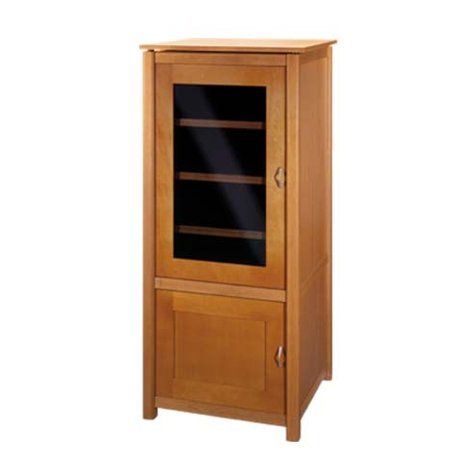
  9. Sanus Systems JFV65 User manual

Sanus Systems JFV65 User manual

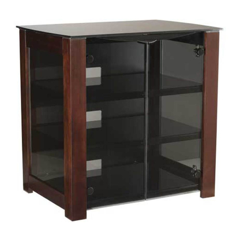
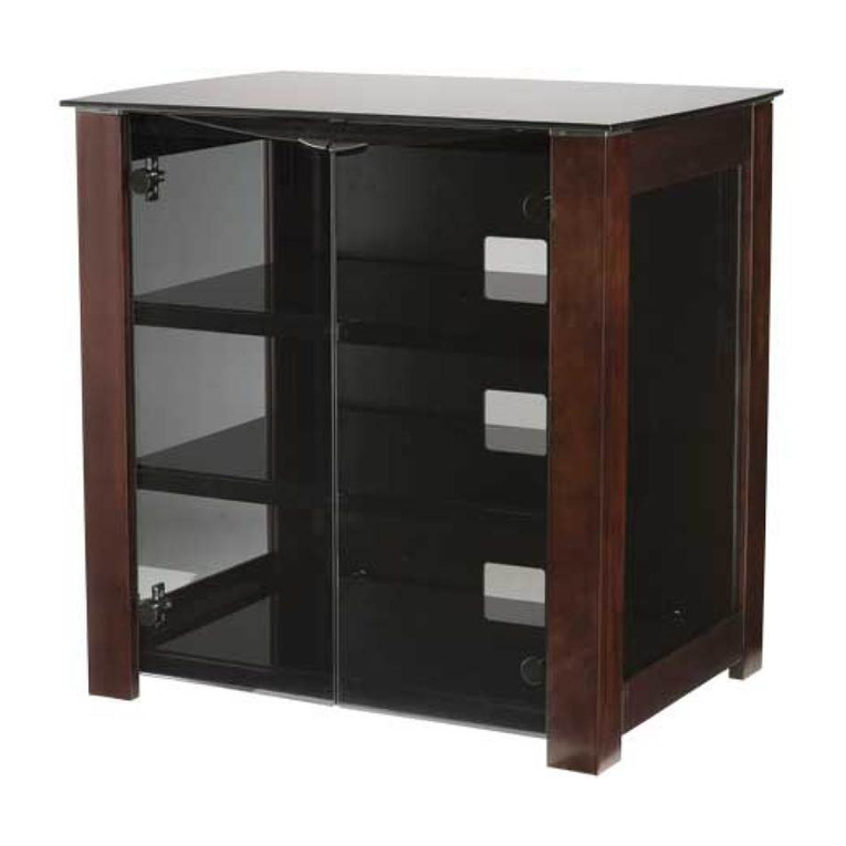
Assembly Instructions for Java Furniture: JFV65 & JFV75
Thank you for Choosing the Java Furniture Line from Sanus Systems. If you have any questions regarding this or any other Sanus
Systems product, please contact us at 800.359.5520 or visit us at www.sanus.com. Our customer service representatives can assist you
quickly with any issues regarding assembly or missing parts. Check carefully to make sure none of the parts are missing or defective.
Never use defective parts. Replacement parts for products purchased from an authorized dealer will be shipped directly to you. Please
call Sanus Systems before returning products to retail stores.
Required Tools: Phillips Screw Driver
Note: Check carefully to make sure you have all the hardware listed below.
Hardware: Hardware shown at actual size.
(18) Cam - a (18) Cam Pin - b (26) Dowel - c
(4) Barrel Nut - d (4) Barrel Nut Bolt - e
(8) M6 Bolt - f (8) Rubber Spacer - g (8) Aluminum Spacer - h
(12) Shelf Pin - i (12) Shelf Pin Screw - j (8) Door Protectors - k
(8) Base Bolt - l (10) Carpet Glide - m (1) Allen Key - n
Sanus Systems 2221 Hwy 36 West, Saint Paul, MN 55113 11.14.16 (6901-100105)
Customer Service: 800.359.5520. See complementary Sanus products at www.sanus.com
(1) Top - o
(1) Bottom - p
(1) Right Inside Panel - q (1) Left Inside Panel - r (1) Right Outside Panel - s (1) Left Outside Panel - t
(2) Side Shelf - u (1) Middle Shelf - v
(2) Front Base Rail - w (2) Side Base Rail - x
(2) Leg - y (2) Door - z (3) Back Panel - aa
Note: Cams should
be tightened in a
clockwise motion
Step 1: Prepare the Top
Place the Top (o) upside down on a soft surface to lessen the chance of scratching. Insert 8 Cam Pins (b) and 8 Dowels (c) into the Top
as seen in Diagram 1. Proceed to tighten each Cam Pin with a Phillips screw driver. Next, orient the Barrel Nut (d) so the hole in its side
faces the hole in the back of the Top. Proceed to insert each Barrel Nut into the hole as shown in the Detailed View of Diagram 1. Then
thread each Barrel Nut Bolt (e) into the hole on the back of the Top, as pictured in the Detailed View of Diagram 1. Tighten each Barrel
Nut Bolt so they protrude a 1/4” from the Top.
Detailed View
d
b
c
e
Diagram 1
o
Step 2: Add Outside Panels
Place each Cam (a) into each Outside Panel (s,t) as shown in Diagram 2. Make sure the arrow on the Cam is pointing toward the hole on
the outside as shown in Detailed View A. Place each Outside Panel on the Top (o), make sure Dowels (c) and Cam Pins (b) align with
the correct holes. The Channel on the back of the Top should be lined up with the Channel in the Outside Panel. Proceed to tighten the
Cams on each Outside Panel in a clockwise motion.
Detailed View
a
Diagram 2
channel c b
o
channel
Step 3: Add Inside Panels
Insert each Cam (a) into each Inside Panel (q,r) in the same manner as you did in Step 2. Place the Inside Panel so that it ts over the
Dowels (c) and Cam Pins (b) as shown in the Detailed View of Diagram 3. Make sure the Inside Panels do not block the Channel. The
Cams on the Inside Panel should be facing the Outside Panels. Tighten each Cam on both Inside Panels.
Detailed View
r
o a
Diagram 3
b c
Step 4: Add Dowels
Insert 8 Dowels (c) into the top of Panels (q,r,s,t) as shown in the Detailed View of Diagram 4. Make sure they are inserted into the holes
closest to the center.
Detailed View
c
Diagram 4
t
s
q
r
t
Note: Cams should
be tightened in a
clockwise motion
Step 5: Add Barrel Nut and Bolt
Place the Bottom (p), with track and channel facing up on a soft surface, which will help prevent scratching. Next, orient the Barrel Nut
(d) so the hole in its side faces the hole in the back of the Top. Proceed to insert the Barrel Nut into the hole as shown in the Detail View
of Diagram 5. Then thread the Barrel Nut Bolt (e) into the hole on the back of the Bottom, as pictured in Diagram 5. Tighten each Barrel
Nut Bolt so that they protrude a 1/4” From the Top.
Detailed View
d
e
Diagram 5
channel
p
track
Step 6: Add Bottom
Flip the Bottom (p) so the track and channel are facing down. Align the bottom piece so it is resting on the Panels (q,r,s,t) with the 4 large
holes toward the back as shown in Diagram 6. Insert a Base Bolt (l) through the Bottom and into the appropriate hole in the Panel. See
the Detailed View of Diagram 6 for assistance.
Detailed View
Diagram 6
l
p
Note: Cams should
be tightened in a
clockwise motion
Step 7: Prepare Bottom
Insert 6 Cam Pins (b) and 6 Dowels (c) into the Bottom (p) as shown in the Detailed View of Diagram 7. Tighten all Cam Pins with a
Phillips screw driver until they are tight.
Detailed View
b
Diagram 7
c
p
Step 8: Assemble Base
Insert 4 Cam Pins (b), 4 Dowels (c), and 10 Cams (a) as shown in Diagram 8. Tighten Cam Pins with a Phillips screw driver. Then, attach
the Front Base Rails (w) to the Side Base Rails (x). Proceed to tighten the 4 Cams on the Side Rails. Once assembled, the rails should
form a solid rectangle.
Diagram 8
c
x w
b
a
Step 9: Add Base Assembly to Bottom
Flip and align the assembled base frame so the holes in the assembled base frame line up with the Dowels (c) and Cam Pins (b) on the
Bottom (p). Proceed to tighten all 6 of the Cams (a) on the Front Base Rails (w) that correspond with the Cam Pins on the Bottom so that
the assembled base frame is secured to the Bottom.
Diagram 9
w
a
p
b
c
Step 10: Add Legs
To add the Legs (y) rst slide the Rubber Spacer (g) so it ts into the Aluminum Spacer (h). Then take a M6 Bolt (f) and insert it through
the Outside Panel (s,t), the Spacer Assembly and nally thread it into the Leg. See the Detailed View of Diagram 10 for assistance. Re-
peat this process for the remaining holes on the left and right leg. Tighten each M6 Bolt with the Allen Key (n) until tight.
Detailed View
y
g
h
Diagram 10
s
f
Note: Cams should
be tightened in a
clockwise motion
Step 11: Add Carpet Glides
Gently tap a Carpet Glide (m) into each Leg (y), and into the locations shown in the Front Base Rails (w) and Side Base Rails (x). See
the Detailed View of Diagram 11 for assistance.
Detailed View
Diagram 11
m
m
w
y
x
Step 12: Add Shelves
Thread the Shelf Pin Screws (j) through the Shelf Pin (i) and into the panel as shown in the Detailed View of Diagram 12. Tighten Shelf
Pin Screws with a Phillips screw driver. Repeat the process until all 12 of the shelf pins are in place. Place Shelves (u,v) in cabinet so
they will t on top of the Shelf Pins. Press down on Shelf rmly until it locks into place.
Note: The connectors on the Side Shelves (u) are closer to the front and back of the shelf than they are on the Middle Shelf (v).
The two identical Shelves are the Outside Shelves.
Detailed View
Diagram 12
t
i
j
Sanus Systems 2221 Hwy 36 West, Saint Paul, MN 55113 11.14.06 (6901-100105)
Customer Service: 800.359.5520. See complementary Sanus products at www.sanus.com
Step 13: Add Back Panels
Insert the Back Panel (aa) by lifting it up into the upper channel, and setting it down into the lower channel as shown in Diagram 13.
After inserting the rst Back Panel, slide it all the way to the left. After inserting the second Back Panel slide it all the way to the right.
Then, insert the last Back Panel into the middle slot.
Note: The last Back Panel that is inserted should go in the middle. Insert the outer two rst. Make sure the left and right Back
Panel slide into the channel in the Outside Panels.
Diagram 13
aa
Step 14: Add Doors
Add 2 Door Protectors (k) to each side of the door as shown in the detailed View of Diagram 14. Hold the Door (z) so the smooth side
of the glass is facing out. Then, insert the Door so that the pegs on the top of the door are inserted into the Channel in the Top (o) and the
bottom wheels t on the Track on the Bottom (p) as shown in Diagram 14. The doors should slide easily on the track.
Detailed View
Diagram 14
k
z
track
Note: If Doors (z) do not slide easily, make sure wheels are sitting properly on the track.

This manual suits for next models

1

Other Sanus Systems Indoor Furnishing manuals
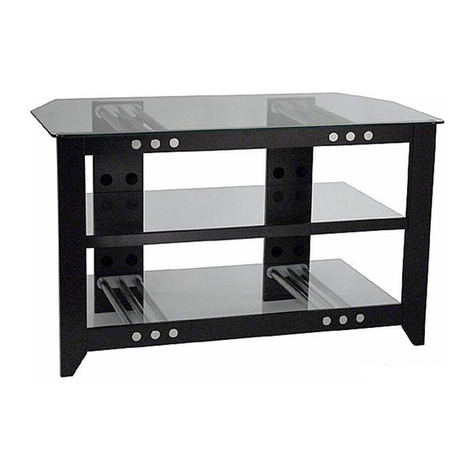
Sanus Systems PFFP2 User manual

Sanus Systems

Sanus Systems PFFP2 User manual

Sanus Systems Sanus Platinum Video Furniture PFPL  PFPL... User manual

Sanus Systems

Sanus Systems Sanus Platinum Video Furniture PFPL PFPL... User manual

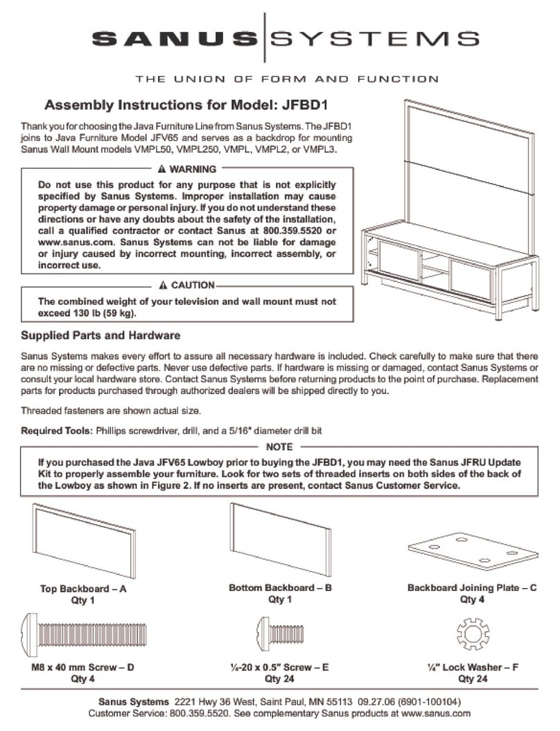
Sanus Systems JFBD1 User manual

Sanus Systems

Sanus Systems JFBD1 User manual

Sanus Systems DFV50 User manual

Sanus Systems

Sanus Systems DFV50 User manual

Sanus Systems SFV49 User manual

Sanus Systems

Sanus Systems SFV49 User manual

Sanus Systems NFCD User manual

Sanus Systems

Sanus Systems NFCD User manual

Sanus Systems WFA37 Installation guide

Sanus Systems

Sanus Systems WFA37 Installation guide

Sanus Systems CFV69 User manual

Sanus Systems

Sanus Systems CFV69 User manual

Sanus Systems PFV47 User manual

Sanus Systems

Sanus Systems PFV47 User manual

Sanus Systems EFAB-II User manual

Sanus Systems

Sanus Systems EFAB-II User manual

Sanus Systems NFA245 User manual

Sanus Systems

Sanus Systems NFA245 User manual

Sanus Systems EFAS-II User manual

Sanus Systems

Sanus Systems EFAS-II User manual

Sanus Systems Sanus Foundations BFV145-B1 User manual

Sanus Systems

Sanus Systems Sanus Foundations BFV145-B1 User manual

Sanus Systems WFAV66 User manual

Sanus Systems

Sanus Systems WFAV66 User manual

Sanus Systems NFV249 User manual

Sanus Systems

Sanus Systems NFV249 User manual

Sanus Systems Sanus Euro Furniture EFAV EFAV-II EFAV-II User manual

Sanus Systems

Sanus Systems Sanus Euro Furniture EFAV EFAV-II EFAV-II User manual

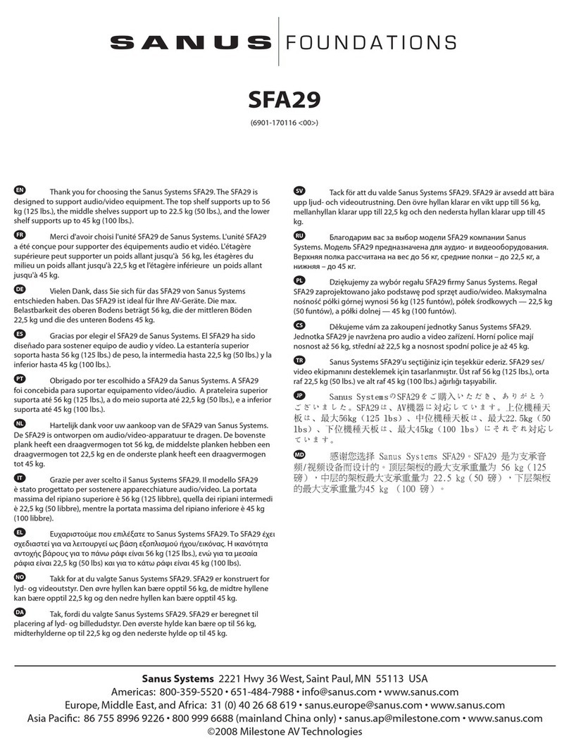
Sanus Systems Sanus Steel AV Foundations SFA29 User manual

Sanus Systems

Sanus Systems Sanus Steel AV Foundations SFA29 User manual

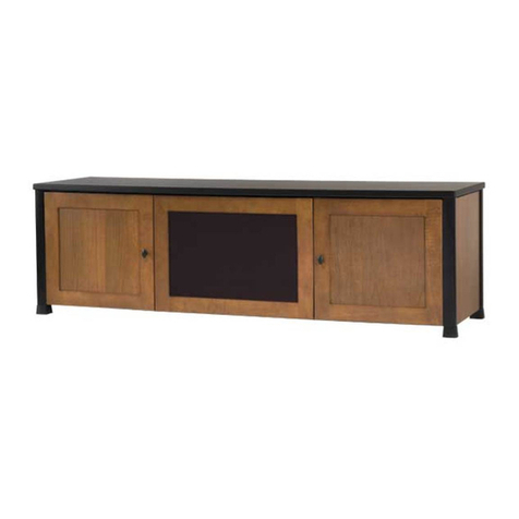
Sanus Systems NF203 Installation guide
Sanus Systems

Sanus Systems NF203 Installation guide

Sanus Systems Sanus Natural AV Foundations NFAV230 User manual

Sanus Systems

Sanus Systems Sanus Natural AV Foundations NFAV230 User manual

Sanus Systems WFA37 User manual

Sanus Systems

Sanus Systems WFA37 User manual
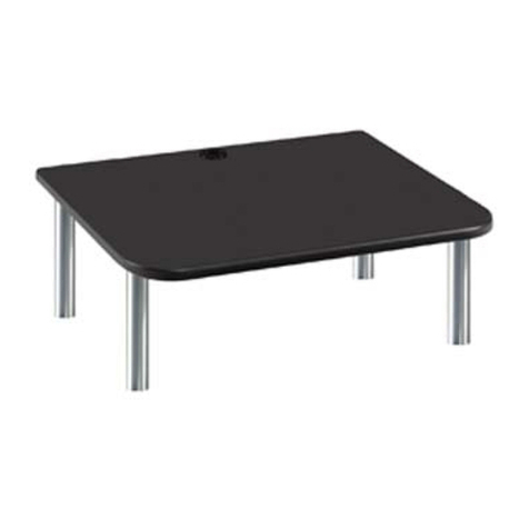
Sanus Systems NF203 User manual

Sanus Systems

Sanus Systems NF203 User manual

Sanus Systems PLATINUM FURNITURE PFPL User manual

Sanus Systems

Sanus Systems PLATINUM FURNITURE PFPL User manual

Sanus Systems JFBD1 User manual

Sanus Systems

Sanus Systems JFBD1 User manual

Sanus Systems CFA56 User manual

Sanus Systems

Sanus Systems CFA56 User manual
Popular Indoor Furnishing manuals by other brands

Step 2 LifeStyle Dream Kitchen 7363 quick start guide

Step 2

Step 2 LifeStyle Dream Kitchen 7363 quick start guide

Aqua One Inspire 40 Assembly instructions

Aqua One

Aqua One Inspire 40 Assembly instructions

home star MAINSTAYS 109073 Assembly instructions

home star

home star MAINSTAYS 109073 Assembly instructions

HAMPTON BAY FRS80812CT-O Use and care guide

HAMPTON BAY

HAMPTON BAY FRS80812CT-O Use and care guide

HAMPTON BAY MORENO VALLEY FWS00610 Use and care guide

HAMPTON BAY

HAMPTON BAY MORENO VALLEY FWS00610 Use and care guide

HunterDouglas Provenance EasyRise Installation operation care

HunterDouglas

HunterDouglas Provenance EasyRise Installation operation care

HunterDouglas RB 500 installation instructions

HunterDouglas

HunterDouglas RB 500 installation instructions

LOWE'S 3439-5IN1 Assembly instructions

LOWE'S

LOWE'S 3439-5IN1 Assembly instructions

Members Mark SMFPC-33-3 Assembly instructions & user manual

Members Mark

Members Mark SMFPC-33-3 Assembly instructions & user manual

SouthShore 3642 Assembly instructions

SouthShore

SouthShore 3642 Assembly instructions

Happy Beds Loxley 4ft Assembly instructions

Happy Beds

Happy Beds Loxley 4ft Assembly instructions

Happy Beds AMERICAN Wooden Triple Sleeper Assembly instructions

Happy Beds

Happy Beds AMERICAN Wooden Triple Sleeper Assembly instructions

Home Styles 4515-95 quick start guide

Home Styles

Home Styles 4515-95 quick start guide

Herman Miller Setu Care and maintenance

Herman Miller

Herman Miller Setu Care and maintenance

Simpli Home brooklyn+max WyndenHall AXCRAMH19-HIC manual

Simpli Home

Simpli Home brooklyn+max WyndenHall AXCRAMH19-HIC manual

mlmeble OLIWIER 07/S Assembly instructions

mlmeble

mlmeble OLIWIER 07/S Assembly instructions

Herman Miller Nelson Assembly instructions

Herman Miller

Herman Miller Nelson Assembly instructions

King Slide 1A68F installation instructions

King Slide

King Slide 1A68F installation instructions

manuals.online logo
manuals.online logoBrands
  • About & Mission
  • Contact us
  • Privacy Policy
  • Terms and Conditions

Copyright 2025 Manuals.Online. All Rights Reserved.