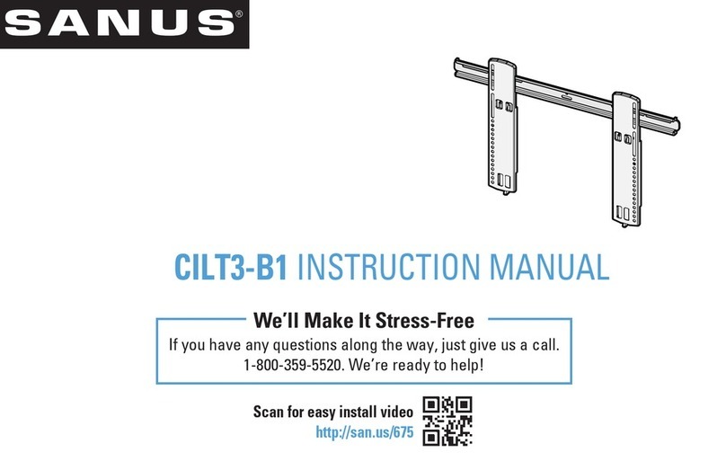
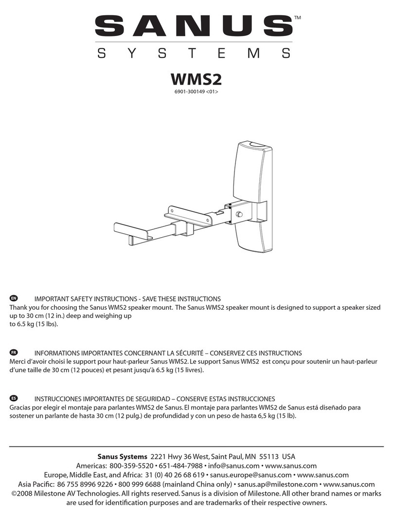
Sanus SASB1 User manual

SASB1
SOUNDBAR
MOUNT
INSTRUCTION
MANUAL
Texto
en
espaiiol,
pagina
12
WE'RE
HERE
TO
HELP
If
you
have
any
questions
along
the
way,
our
US-based
install
experts
are
standing
byto
help.
ij
Call
us
at:
800-359-5520
S
Or,
chat
at:
SANUS.com/chatSP
IMPORTANT
SAFETY
INSTRUCTIONS
PLEASE
READ
ENTIRE
MANUAL
PRIOR
TO
USE
-
SAVE
THESE
INSTRUCTIONS
Before
You
Begin
Please
verify
the
following
items:
□
Your
TV,
sound
bar,
sound
bar
mount,
and
any
accessories
you
plan
to
install
DO
NOT
EXCEED
the
specified weight limit
of
your
TV
wall
mount.
□
You
read
and
understand these directions.
□
You
refer
to
the
documentation that
came
with your
sound
bar,
your
TV
and
your
TV
wall
mount
for additional guidance.
A.
WARNING:
•
This
soundbar
mount
is
only
designed for
use
with
TV
wall
mounts
that
meet
UUTUV
safety certifications.
•
This
soundbar
mount
is
ONLY
designed
to
mount
BELOW
the
television
(see
Figure
1).
•
This
soundbar
mount
is
designed
to
be
installed
and
utilized
only
as
specified
in
this
manual.
The
manufacturer
is
not
responsible for improper
assembly,
use,
or
handling
of
this product.
•
Failure
to
follow
these
instructions
could
result
in
an
unstable
situation
that
may
result
in
property
damage
or
personal
i
njury.
Weight Restrictions
I
Weight
Limit for SASB1 I
Weight
Limit for Your TV Mount
A
CAUTION:
Avoid
potential personal injuries
and
property
damage!
ITi7l
~
(@)
Figure 1
DO
NOT
EXCEED
20 lbs. (9.0
kg)
for
this
Soundbar Mount
The
weight
of
your
TV,
PLUS
this
sound
bar
mount,
your
sound
bar,
and
any
accessories,
MUST
BE
LOWER
than
the
maximum
weight
rating
of
your
TV
mount.
SeeyourTVmount'smanualformaximumweightallowed.
20
lbs.
(9.0
kg)
~
a
Soundbar
Mount
+
(plu
s)
Your
Soundbar
+
(plus)
-
a
ANY
Other
Accessories
+
(plus) a
Your
TV
-
-
(equals) a
Maximum
for
Your
TV
Mount

Items Needed
Phillips
Screwdriver
Level
PARTS INCLUDED
Your
TV
Mount
Manual
Ul/TUV
Certified
TV
Wall
Mount*
*
Your
TV
wall
mount
may
vary
from
the
illustrations throughout this
manual.
NOTE
that
the
procedure
to
install
the
soundbar
is
the
same.
A
WARNING:
This
product
contains
small
items
that
could
be
a
choking
hazard
if
swallowed.
Before
starting
assembly,
verify
all
parts
are
included
and
undamaged
.
If
any
parts
are
missing
or
damaged
,
do
not
return
the
damaged
item
to
your
dealer;
contact
Customer
Service.
Never
use
damaged
parts!
•
NOTE:
Not
all
hardware included will
be
used
.
,-----------------------.---------r----------,
2
Horizontal
Bracket
CD
OTY.1
Arm
Bracket A
CD
OTY.1
M4
MG
MB
Arm
Bracket B
CD
QTY.1
~
Bottom
Bracket
CD
OTY.2
'
Soundbar
Screws
(qty
.2
each)
[Only one size fits your Soundbar)
M4
~
MS
M4x
10mm
~
M4x
16mm
MG
(e
m
TV
Screws
(qty
.4
ea
c
h)
[Only one size fits your
TV)
M4x30mm
M4
x
50mm
'
Soundbar
Washers
(qty
.2
each)
0
M4
/
M5
Washer
@
M6
Washer
<ln
Washer
"T
(qty.
4
each)
M4
Washer
©
MB
/M6 Washer
CD
Spacer:
16mm
•
OTY.2
Cb
Key
Hole
Screw
(1/4
-
20)
4D
OTY.2
(D
Spacer
"T
[If
ne
c
essary]
(qty
.4
each)
I
Spacer:
2.5mm
0
Interface Washer
CD
QTY.2
C([[r
Knob
a,
OTY.2

STEP
1:
PREPAREYOURTV
[IF
MOUNTED]
A
CAUTION:
Follow your
TV
mount's manual
for
instructions
on
how
to safely remove your
TV
and
TV
bracket.
•
NOTE:
Your
TV
wall
mount may vary from the illustrations
throughout
this manual -the procedure to install the
soundbar is the same.
STEP
3Ba
(if
needed)
□
STEP
2:
ASSEMBLE SOUNDBAR
MOUNT
Remove
screws®
and
save
for
STEP
2e.
Measure
the
distance
between
the
mounting
holes
on
your
soundbar.
3

p:
Based
on
your
sound
bar
measurement,
rotate
arm
brackets@/@
left
or
right,
to
align
with your
sound
bar
mounting
holes,
but
not overhanging
the
ends
of
your soundbar
or
covering
up
any
cable
connections.
i~i 7
p:
• i
oo
II
• 7 •
oo
II
•
00
II
fl
Ii
I I
l"
'l r
{J
0
f)
~
s
~
"
IV-
s
{J
~
6.6
in.
to
19.5
in.
I
12
in.
to
22.5
in.
I
20
in.
to
31
in.
I
22.5
in.
to
35.5
in.
I
Insert
the
soundbar
arm
brackets <f)
and
(!D into
the
horizontal bracket (iD.
•
NOTE:
Holding
the
lever inward
as
shown,
helps
to
slide
the
arms
.
NOTE:
The
channel
of
the
horizontal
bracket
<iD
will rest
ON
your
TV.
Re-attach
the
screws®
onto
the
arm
brackets <f) and@.
NOTE:
The
flat
side
of
the
arm
brackets
<f)
and
(!D
rests
ON
the
sound
bar.
A.
CAUTION:
The
screws®
MUST
be
installed
to
secure
the
arms
to
the
horizontal bracket (iD.

STEP
3:
INSTALLTHE SOUNDBAR
MOUNT
ONYOUR
TV
Determine
which
screw
diameter
fits
your
TV
-M4, M6,
or
M8.
Only
one
screw
size
fits your
TV.
M4
M6
M8
t
0 0 0
Step
3A
•
for
Flat
Back
TV
[TV
brackets layflatonyourTV]
follow
Step 3A
on
PAGE
6.
0 If your
TV
included inset
spacers
or
wall
mount
adapters,
use
them
UNDER
the
soundbar
mount
hardware.
Step
3B
•
for
Flat
Back
TV
with
Extra
Space
Needed
[for
deep
inset
holes
or
cable
interference]
follow
Step
3B
on
PAGE
7.
Inset
Holes
Cables
•
for
Rounded
or
Irregular
Back
TV
[TV
brackets
NOT
resting
flat
on
your
TV]
follow
Step
3B
on
PAGE
7.
Rounded
Back
A
CAUTION:
Verify adequate thread engagement with your screw
cm,,
washer
cm),
spacer
8;(m,
combination
AND
sound
bar
bracket
(D.
-Too
short
will
not
hold
your
TV.
-Too
long
will
damage
your
TV.
Too
Short
Too
Long
Correct
Correct
5

STEP
3A
6
Place
the
16mm
spacers
cm>
over
your
TV's
top
mounting
holes
and
the interface washers<®
over
the
bottom
mounting
holes.
Center
the
soundbar horizontal bracket
<Dover
the interface washers(®
on
your
TV's
bottom
mounting
holes.
Center
your
TV
mount
bracket(s)
on
top
of
the
16mm
spacers
cm>
and
the
sound
bar
bracket
(D.
Secure
the
TV
mount
and
sound
bar
mount
to
your
TV
using
the supplied
TV
screws
cm,
and
washers
(m,.
A
CAUTION:
be
sure
to
use
correct
len
th
screws.
Your
TV
mount
1

STEP 3B
I :
Place
your
1V
mount
spacers
over
your
lV's
mounting
holes.
Then
place
the
16mm
spacers(m)overthe
spacer
on
thetop
mounting
holes
and
the
interface
washers
<m>
over
the
spacer
on
the
bottom
mounting
holes.
I
I
0
I
~
I I
(!)
&
Center
the
soundbar horizontal bracket
G)
over
the
interface washers
<m>
on
your
TV's
bottom
mounting
holes.
TV
mount I
spacers '
Center
your
TV
mount bracket(s)
on
top
of
the
16mm
spacers
(m)
and
the
sound
bar bracket G).
Secure
the
TV
mount
and
sound
bar
mount
to
your
TV
using
the
supplied
TV
screws
cm,
and
washers
<m,.
A
CAUTION:
be
sure
to
use
correct
len
th
screws.
Your
TV
mount
7

STEP
4:
INSTALLYOUR SOUNDBARTO THE ARMS
Center
your
sound
bar
under
the
sound
bar
mount,
and
adjustthe
arms
<!P}/<l'E)
over
your
soundbar
mount
holes.
&
NOTE:
Holding
the
lever inward
as
shown,
helps
to
slide
the
arms.
Attach your
soundbar,
based
on
the
mounting
holes
of
your
soundbar.
Look
at
the
mounting
holes
on
the
back
or
bottom
of
your
sound
bar
to
determine
your
install
method
A,
B
or
C.
4A:
Back-Mounted
Key
hole
slots
~
(I)
PAGE
8
4B:
Back-Mounted
Threaded
inserts
~
@
PAGE9
4C:
Bottom-Mounted
Threaded
inserts
~
~
PAGE
9
4A:
Back-Mounted
Key
Hole Slots
Assemble
knobs
Q)
and
keyhole
screws@.
Attach brackets(@
and
<lD
to
your
sound
bar
using
the
knob
assemblies.
lighten
the
screws
(D
to
secure
the
arms
in
place.

4B:
Back-Mounted
Threaded
Inserts
Attach
the
sound
bar
arm
brackets~
and
@to
your
sound
bar
using
two screws
E)
and
washers
G).
4C:
Bottom-Mounted
Threaded
inserts
Align the
bottom
brackets~
with your soundbar
mounting
holes
and
attach
using
two screws
E)
and
washe_
rs
G).
NOTE:
Use
the
2.5mm
spacers@ if
the
supplied screws
are
too
long
for your
sound
bar.
Install
the
bottom
brackets~
to
the
sound
bar
arms
using
the
screws®
and
washers
@.
lighten
the
screws
CD
to
secure
the
arms
in
place.
Remove
screws®
and
washers@from brackets~-
lighten
the
screws
CD
to
secure
the
arms
in
place.

STEP
5:
HANGYOUR TV
BEFORE
hanging,
verify
the
depth
of your soundbar will not interfere with
the
wall after mounting your
TV.
Adjust
the
depth
of
your soundbar
as
needed,
by
loosening screw
CD.
Tighten
screw
CD
after adjustments.
Attach
the
magnet
of
release
cord@,
to
back
of
the
sound
bar
mount,
for
easy
access
during
adjustments.
Follow your
TV
wall
mount
installation
manual
to
hang
your
TV
assembly.

ADJUSTMENTS
HEIGHT
ADJUST:
Pull
and
hold
release
cord®
to
raise
or
lower your
soundbar.
A.
CAUTION:
be
sure
to
support your
soundbar
with
one
hand
while
moving.
·
DEPTH
ADJUST
[For
back
mount
installations]:
1.
Loosen
the
knobs
or
screws,
(depending
on
your
installation
option),
on
the
back
of
your
soundbar.
2.
Loosen
locking
screws
(D.
3.
Move
your soundbar
to
desired
position.
4.
Tighten
all
knobs/screws
when
finished
adjustment.
OPTION
A:
Back-Mounted
Key Hole Slots
OPTIONB:
Back-Mounted
Threaded
Inserts
OPTIONC:
Bottom-Mounted
Threaded
insens
DEPTH
ADJUST
[For
bottom
mount
installations]:
Loosen
the
screws
on
the
bottom
of
your
soundbar
to
slide
your
soundbar
in
or
out.
Tighten
the
screws
when
finished
adjustment.

INSTRUCCIONES
DE
SEGURIDAD
IMPORTANTES.
LEA
TODO
EL
MANUAL
ANTES
DE
UTILIZAR
EL
PRODUCTO
POR
PRIMERA
VEZ
.
CONSERVE
ESTAS
INSTRUCCIONES
jAntes
de
empezar,
asegurese
de
que
este
es
el
producto
adecuado
para
usted!
Verifique
las
siguientes
puntos
:
~
Que
su
televisor,
la
barra
de
sonido,
la
montura
de
barra
de
sonido
y
cua
l
quier
accesorio
que
vaya
a
instalar
NO
EXC
ED
AN
el
limite
de
peso
especificado
del
soporte
del
televisor.
Que
va
aleery
que
comprende
estas
indicaciones.
Que
consulta
la
documentaci6n
proporcionada
con
su
barra
de
sonido,
su
televisor
y
su
soporte
de
pared
para
televisor
para
obtener
directrices
adicionales.
A
PRECAUCION
:
Para
evitar
posibles
lesion
es
personales
ydaiios
materiales:
•
Esta
montura
de
barra
de
sonido
ha
sido
diseiiada
exclusivamente
para
su
uso
con
soportes
de
pared
para
televisores
que
cumplan
las
certificaciones
externas
de
seguridad.
Esta
montura
de
barra
de
sonido
ha
sido
diseiiada
EXC
L
USIVAMENTE
para
colocarse
debajo
del
televisor lconsulte
la
Figura
3).
•
Esta
montura
de
barra
de
sonido
esta
diseiiado
para
instalarse y utilizarse
exclusivamente
coma
se
especifica
en
este
manual.
El
fabricante nose
hace
responsable
par
el
armada,
manipulaci6n
o
uso
incorrectos
de
este
producto.
•
No
seguir
estas
instrucciones
podria
ocasionar
una
situaci6n
inestable
que
puede
causar daiios materiales o
lesiones
fisicas.
Limite de peso
de SASB1
NO
EX
CEDA los 9,0
kg
(
20
lb) en
la montura de barra de sonido
ILimite de peso de
su
soporte para televisor I
A
PRECAUCION
:
Evite
posible~
lesiones personales y daiios
materiales.
El
peso
del
televisor,
MAS
la
montura
de
la
barra
de
sonido,
la
barra
de
sonido
y
las
accesorios
OEBE
SER
MENOR
que
el
peso
maxima
permitido
para
el
sororte
del
te
levisor.
Consulte
el
peso
maxima
permitido
en
el
manua
de
su
soporte
para
televisor.
I
PIEZAS
y
ELEMENTOS
DE
MONTAJE
SUMINISTRADOS
I
Herramientas
necesarias
Destornillador
Nivel
lll
~anual
de
soporte
para
TV
El
soporte
de
pared
para
su
televisor
puede
variar
de
las
ilustraciones
que
aparecen
en
este
ma
n
ual.
Tenga
en
cuenta
que
el
procedimiento
de
instalaci6n
de
la
barra
de
sonido
no
varfa.
AADVERTENCIA:
Riesgo
de
atragantamiento.
Este
producto
contiene
piezas
pequeiias
que,
en
caso
de
sertragadas,
podrian
causar
asfixia.
Antes
de
comenzar
a
montar
la
unidad,
verifique
que
dispone
de
todas
las
piezas
y
que
se
encuentran
en
buen
estado.
Si
no
dispone
de
todas
las
piezas
o
alguna
esta
daiiada,
NO
devuelva
el
elemento
defectuoso
al
distribuidor.
P6ngase
en
contacto
con
el
servicio
de
atenci6n
al
cliente.
Nunca
utilice
piezas
en
mal
estado.
\ll
NOTA:
Nose
utilizaran
todos
las
elementos
de
montaje
incluidos
en
este
kit.
PASO
1:
Prepare
su
televisor
(siesta
instalado)
A
PRECAUCION:
Sig
a
las
instrucciones
del
manual
de
instalaci6n
para
retirar
de
forma
segura
su
televisor y
el
soporte
del
mismo.
\ll
NOTA:
El
soporte
de
pared
para
su
televisor
puede
variar
de
las
ilustraciones
que
aparecen
en
este
manual.
Tenga
en
cuenta
que
el
procedimiento
de
instalaci6n
de
la
barra
de
sonido
no
varia.
PASO
2:
Ensamble
el
montaje
de
la
barra
de
sonido
a.
Retire
las
tornillos
IP)
de
las
soportes
del
brazo
de
la
barra
de
sonido
102
y
03).
Nata:
Guarde
las
tornillos.
Debera
volver
a
colocarlos
en
el
PASO
2e.
b.
Mid
a
la
distancia
entre
las
orificios
de
montaje
de
la
barra
de
sonido.
c.
Basandose
en
las
medidas
de
la
barra
de
sonido,
gire
las
soportes
del
brazo
102
y03)
a
la
izquierda
oa
la
derecha
para
alinearlos
con
los
agujeros
de
montaje
de
la
barra
de
sonido.
Asegurese
de
que
las
brazos
no
sobresalgan
de
las
extremos
de
la
barra
de
sonido
ni
cubran
las
conexiones
de
las
cables.
d.
lnserte
las
soportes
del
brazo
de
la
barra
de
sonido
102
y
03)
en
el
soporte
horizontal
101
).
Nata:
La
sujeci6n
de
la
palanca
hacia
adentro
ayuda
a
deslizar
las
brazos.
Nata:
El
canal
en
el
soporte
horizontal
(01)
se
apoya
en
su
televisor.
Nata:
El
lado
piano
de
las
soportes
de
las
brazos
102
y03)
se
apoya
en
la
barra
de
sonido.
e.
Vuelva
a
colocar
las
torni
ll
os
IP)
en
las
soportes
de
las
brazos
102
y
03).
CUIDADO:
Los
tornillos
IP)
deben
instalarse
para
fijar
las
brazos
al
soporte
horizontal
101
).
PASO
3:
Ensamblaje
yfijaci6n
del
soporte
de
la
barra
de
sonido
Determine
el
diametro
de
las
tornillos
para
su
monitory
su
tipo
de
televisor:
M4,
M5, M6,
o
M8.
•
Para
televisores
con
dorso
piano,
siga
el
Paso
3A
en
la
pagina
6.
•
Para
televisores
con
dorso
piano,
Y
si
necesita
mas
espacio
para
cables,
concavidades
oprotuberancias
siga
el
Paso
3B
en
la
pagina
7.
• P r e i r · irr I r n r · · I B n
la
a
ina
7.
A
PRECAUCION
:
Verifique
el
enrosque
adecuado
de
la
combinaci6n
tornillo/arandela/espaciador
ytodos
las
soportes.
-Si
es
demasiado
corto,
no
sujetara
el
televisor.
-Si
es
demasiado
largo,
daiiara
el
televisor.
PASO
3A
a.
Coloque
las
espaciadores
de
16
mm
116)
sabre
las
orificios
de
montaje
superiores
del
televisory
las
arandelas
de
interfaz
117)
sabre
las
orificios
de
montaje
inferiores.
b.
Centre
el
soporte
horizontal
de
la
barra
de
sonido
101)
sabre
las
arandelas
de
interfaz
117)
en
las
ordicios
de
montaje
inferiores
de
su
televisor.
c.
Centre
sus
soportes
de
montaje
deltelevisor
en
la
parte
superior
de
las
espaciadores
de
16
mm
116)
yen
el
soporte
de
la
barra
de
sonido
101).
Sujete
el
soporte
de
montaje
del
televisory
el
soporte
de
montaje
de
la
barra
de
sonido
al
televisor
con
las
tornillos
y
arandelas
suministrados.
CUIDADO:
Asegurese
de
utilizar
l
as
tornillos
de
la
longitud
correcta.
PASO
3B
a.
Coloque
las
espaciadores
de
montaje
del
televisor
sob
re
los
orificios
de
montaje
del
televisor.
A continuaci6n,
coloque
los
espaciadores
de
16
mm
11
6)
sob
re
l
as
espaciadores
en
las
orificios
de
montaje
superi-
ores
y
las
arandelas
de
interfaz
117)
sabre
el
espaciador
en
las
orificios
de
montaje
inferiores. b.
Centre
el
soporte
horizontal
de
la
barra
de
sonido
101)
sabre
las
arandelas
de
interfaz
117)
en
los
orificios
de
montaje
inferiores
de
su
televisor.
c.
Centre
sus
soportes
de
montaje
del
televisor
en
la
pa
rte
superior
de
las
espaciadores
de
16
mm
116)
yen
el
soporte
de
la
barra
de
sonido
101
).
Sujete
el
soporte
de
montaje
del
televisor y
I
rt
d t . d I b d
'd
It
I . I t
·11
d I
..
t d
CU
I
DADO
A . d tT I t
·11
d I I
·1
d t. .
PASO
4:
lnstalaci6n
de
su
barra
de
sonido
a
los
brazos
a.
Centre
la
barra
de
sonido
en
la
pa
rte
inferior
del
televisory
ajuste
las
brazos
del
montaje
de
la
barra
de
sonido
sabre
las
orificios
de
la
misma.
Nata:
La
sujeci6n
de
la
palanca
hacia
adentro
ayuda
a
deslizar
las
brazos.
b.
Mire
las
agujeros
de
montaje
en
la
parte
posterior
o
inferior
de
la
barra
de
sonido
para
determinar
que
metodo
se
necesita
usar.
Para
las
ranuras
de
bocallave
para
el
montaje
posterior
refierase
a
PASO
4A:
Ranuras
de
bocallave
para
el
montaje
posterior
en
la
pagina
8.
Para
las
insertos
con
rosca
montados
en
la
parte
posterior
refierase
a
la
secci6n
PASO
4B:
lnsertos
con
rosca
de
la
pa
rte
posterior
en
la
pagina
9.
Para
insertos
con
rosca
montados
en
la
pa
rte
inferior,
refierase
a
la
secci6n
PASO
4C
-
lnsertos
con
rosca
de
la
parte
inferior
en
la
pagina
9.
I
PASO
4A:
Ranuras
de
bocallave
para
el
montaje
posterior
a.
Monte
las
perillas
(25)
y
las
tornillos
para
las
ranuras
de
bocallave
124).
Sujete
las
soportes
del
brazo
de
la
barra
de
sonido
102)
y
103)
a
su
barra
de
sonido
utilizando
el
juego
de
perillas.
b.
Apriete
las
tornillos
Ill
para
fijar
las
brazos
en
su
sitio.
PASO
48:
lnsertos
con
rosca
de
la
parte
posterior posterior
a.
Fije
las
soportes
del
brazo
de
la
barra
de
sonido
102
y
03)
a
la
barra
de
sonido
con
dos
tornillos 11
8,
19,
20,
o
21)
y
las
arandelas
122
o
23).
b.
Apriete
las
tornillos
Ill
para
fijar l
as
brazes
en
su
sitio.
PASO
4C:
lnsertos
con
rosca
de
la
parte
posterior
inferior
a.
Alinee
las
soportes
inferiores
104)
con
los
orificios
de
montaje
de
la
barra
de
sonido
y
sujetelos
con
dos
tornillos
118,
19,
20,
a
21
Iy
las
arandelas
122
o
23).
Si
las
tornillos
suministrados
son
demasiado
largos
para
la
barra
de
sonido,
utilice
las
espaciadores
de
2.5
mm
115).
b.
Retire
las
tornillos
IS)
y
las
arandelas
IW)
de
las
soportes
inferiores
104).
c.
lnstale
las
soportes
inferiores
104)
en
las
brazos
de
la
barra
de
sonido
utilizando
las
tornillos
IS)
las
arandelas
IW).
d.A
riete
las
tornillos Il l
ara
fi'ar
las
brazos
en
su
sitio.
a.
Asegurese
de
que
la
barra
de
sonido
no
toque
la
pared
cuando
monte
el
televisor.
Ajuste
la
profundidad
de
la
barra
de
sonido
segun
sea
necesario
aflojando
el
tornillo
Ill.
Apriete
el
tornillo
LI
despues
de
las
ajustes.
b.
Ajuste
la
altura
de
la
cuerda
de
liberaci6n
IR)
a
la
pa
rte
inferior
de
la
barra
de
sonido
para
facilitar
el
acceso
durante
las
ajustes.
c.
Siga
las
instrucciones
del
manual
de
instalaci6n
del
soporte
de
montaje
en
pared
del
televisor
para
colgarlo.
Ajustes
Ajus
te
de
la
altura
de
la
barra
de
sonido
:
Nata:
Dependiendo
del
tipo
de
soporte
de
montaje
en
pared
del
televisor
que
tenga,
es
posible
que
tenga
que
quitar
el
televisor
de
la
pared
para
ajustar
la
altura
de
la
barra
de
sonido.
lire y
sostenga
la
cuerda
de
liberaci6n
IR)
para
subir
o
bajar
la
barra
de
sonido.
CUIDADD:
Asegurese
de
apoyar
la
barra
de
sonido
con
una
mano
mi
entras
la
mueve.
Ajuste
de
la
profundidad
de
la
barra
de
sonido
(Para
una
ins
t
alac
i
6n
de
montaje
en
la
parte
posterior)
:
Nata:
D
ependiendo
del
tipo
de
soporte
de
montaje
en
pared
del
televisor
que
tenga,
es
posible
que
tenga
que
quitar
el
televisor
de
la
pared
para
ajustar
la
altura
de
la
barra
de
son
i
do.
1.
Afloje
las
perillas
125)
ol
as
tornillos
118,
1
9,
20,
o
21).
ldependiendo
de
la
opci6n
de
instalaci6n),
en
la
parte
poste
r
ior
de
la
barra
de
sonido.
2.
Afloje
las
tornillos
de
bloqueo
Ill
que
fijan
las
soportes
de
las
brazos
102
y
03).
3.
Mueva
la
barra
de
sonido
a
la
posici6n
que
desee.
4.
Apriete
todas
l
as
per
i
llas
ytornillos
cuando
termine
de
ajustar
la
profundidad.
Ajuste
de
la
profundidad
de
la
barra
de
sonido
(Para
una
instalaci6n
en
la
pa
rte
inferior):
1.
Afloje
las
tornillos
que
sujetan
la
pa
rte
inferior
del
soporte
14)
a
la
pa
rte
inferior
de
la
barra
de
sonido
y
deslice
la
barra
de
sonido
hacia
dentro
a
hacia
fuera.
2.
Apriete
todas
las
perillas
ytornillos
cuando
!ermine
de
ajustar
la
profundidad.
Legrand
AV
Inc.and its affiliated corporations
and
subsidiaries (collectively, "Legrand"), intend
to
make
this
manual
accurate
and
complete. However, Legrand
makes
no
claim that the information
contained herein covers
all
details, conditions, or variations. Nor
does
it provide for every possible contingency
in
connection with
the
installation
or
use
of this product.
The
information
contained
in
this document
is
subject
to
change without notice
or
obligation of
any
kind.
Legrand
makes
no
representation of warranty, expressed
or
implied, regarding the information contained
herein.
Legrand
assumes
no
responsibility for accuracy, completeness or sufficiency of the information contained
in
this document.
©2019
Legrand
AV
Technologies.
All
rights reserved.
Sa
nus
is
a division of
Legrand.
All
other
brand
names
or marks
are
used
for identification purposes
and
are
trademarks of their respective owners.
Le
grand AV Inc. • 6436 Ci
ty
West Parkway • Eden Prairi
e,
MN
55344
USA
6901-602386-00
Other manuals for SASB1
1
Table of contents
Other Sanus Rack & Stand manuals

Sanus
Sanus FSF207 User manual

Sanus
Sanus WSECS1-B2 User manual

Sanus
Sanus SSMK1 User manual

Sanus
Sanus WMS3 User manual

Sanus
Sanus VUEPOINT F55 User manual

Sanus
Sanus BMF320 User manual

Sanus
Sanus SAN213 User manual

Sanus
Sanus VLT5 User manual

Sanus
Sanus VTM27 Installation instructions

Sanus
Sanus CFA16SM User manual
Popular Rack & Stand manuals by other brands

Sharp
Sharp PN-ZS701 Operation manual

OBO Bettermann
OBO Bettermann HE 60UH2 Mounting instructions

Armstrong
Armstrong VIDASHIELD Assembly and installation instructions

PEERLESS
PEERLESS DST360 Installation and assembly

Steren
Steren MOR-61 user manual

Alvin
Alvin Mobile Step-Design File Tube Rack WSF36 Assembly instructions