8
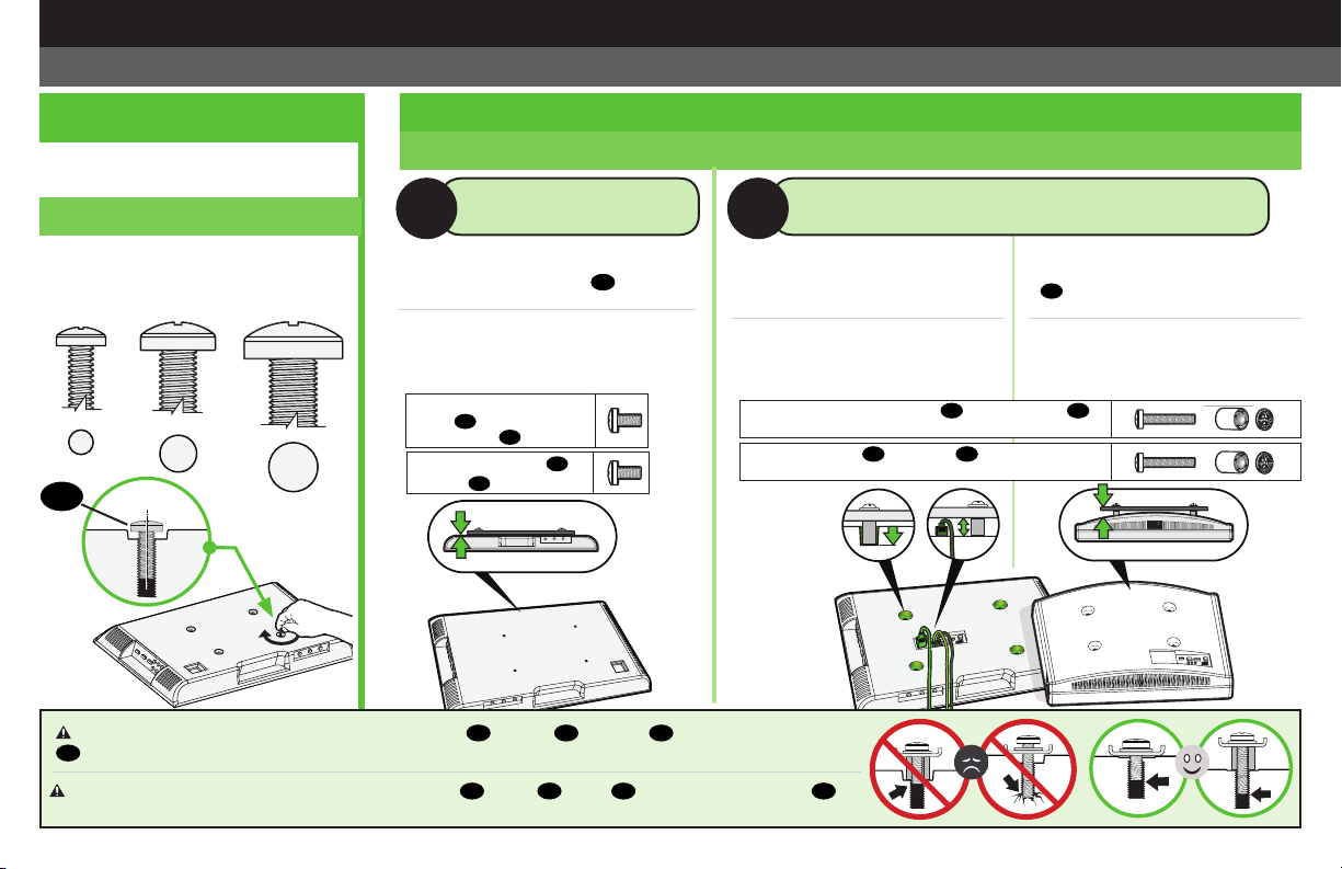
1.2 Select TV Screw Length and Spacers
1,2 Seleccione la longitud de los tornillos para el televisor
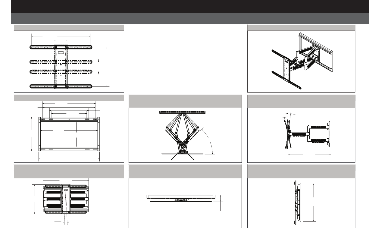
• Televisor con dorso plano
[Los soportes del televisor 04 se apoyan
de manera plana en él]
• Flat Back TV
[TV brackets lay flat on your TV]
SIN ESPACIADOR
NO SPACER CON ESPACIADOR
SPACER NEEDED
A B
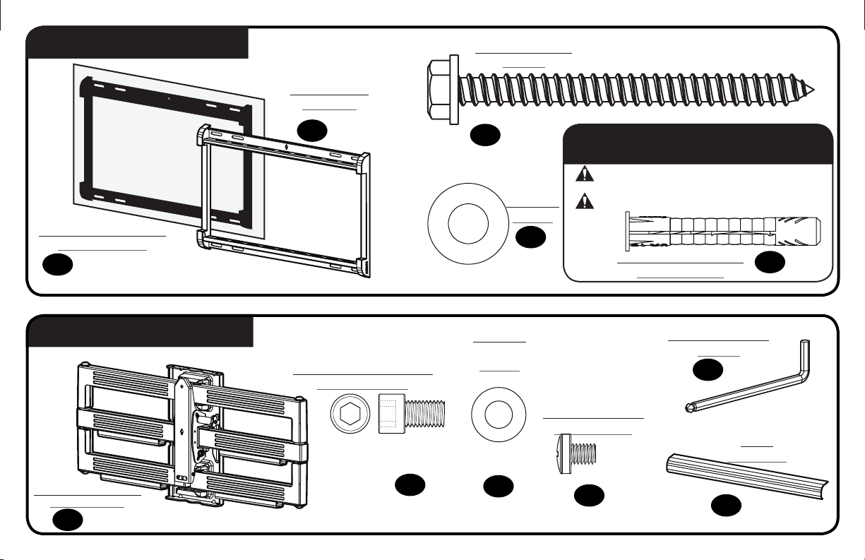
CAUTION: Verify adequate thread engagement with your screw 01 , washer 02 , spacer 03 combination AND TV bracket 04 .
—Too short will not hold your TV. —Too long will damage your TV.
1.1 Select TV Screw Diameter
1,1 Seleccione el diámetro de los
tornillos para el televisor
Only one screw size fits your TV.
M4 M6 M8
01
Use short TV screws 01 .
Spacers 03 not needed.
PRECAUCIÓN: Verifique que el tornillo o la combinación de tornillo 01 , arandelas 02 , espaciador 03 y placas de sujeción del televisor
04 enrosquen correctamente. —Si el tornillo es demasiado corto no sostendrá el televisor. —Si es demasiado largo dañará el televisor.
Use los tornillos del televisor
cortos 01 . No hacen falta
espaciadores 03 .
• Televisor con dorso plano
con necesidad de espacio adicional
[para orificios empotrados o interfe-
rencia de cables]
• Televisores con dorso plano o
irregular [Los soportes del televisor
04 NO se apoyan de manera plana
en él]
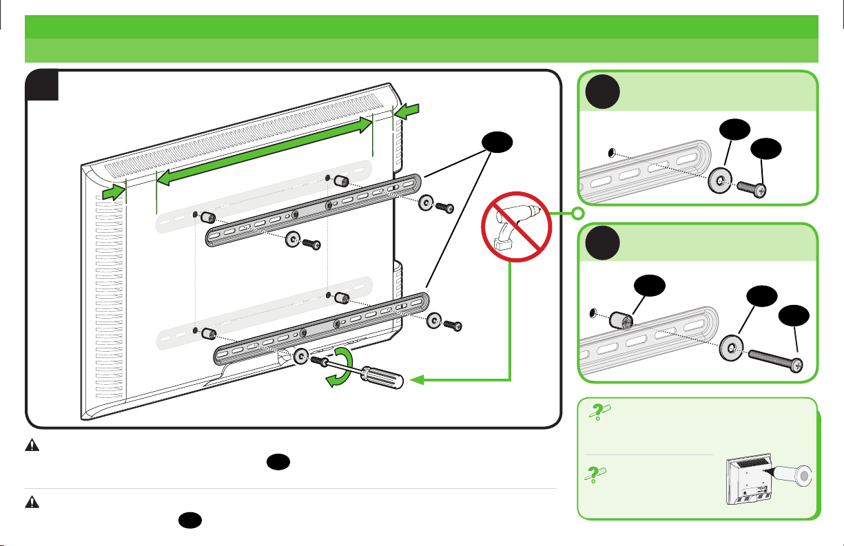
STEP 1 Attach TV Bracket to TV
PASO 1
Fijar el soporte del televisor al televisor
Solo un tamaño de tornillo es
compatible con su TV.
Use los tornillos del televisor largos 01 y los espaciadores 03
para crear espacio adicional entre el televisor y el soporte.
Use long TV screws 01 and spacers 03 to create extra space
between the TV and TV bracket.
• Flat Back TV with extra space needed
[for deep inset holes or cable interference]
• Rounded or Irregular Back TV
[TV brackets NOT resting flat on your TV]