4
Parts and Hardware for STEP 1
22mm
M6 x 12mm
M6 x 35mm
2.5mm
5mm
M8 x 50mm
M6 x 20mm
M8 x 16mm M8 x 20mm
M8 x 40mm
M8 x 30mm
TV Bracket
TV Bracket
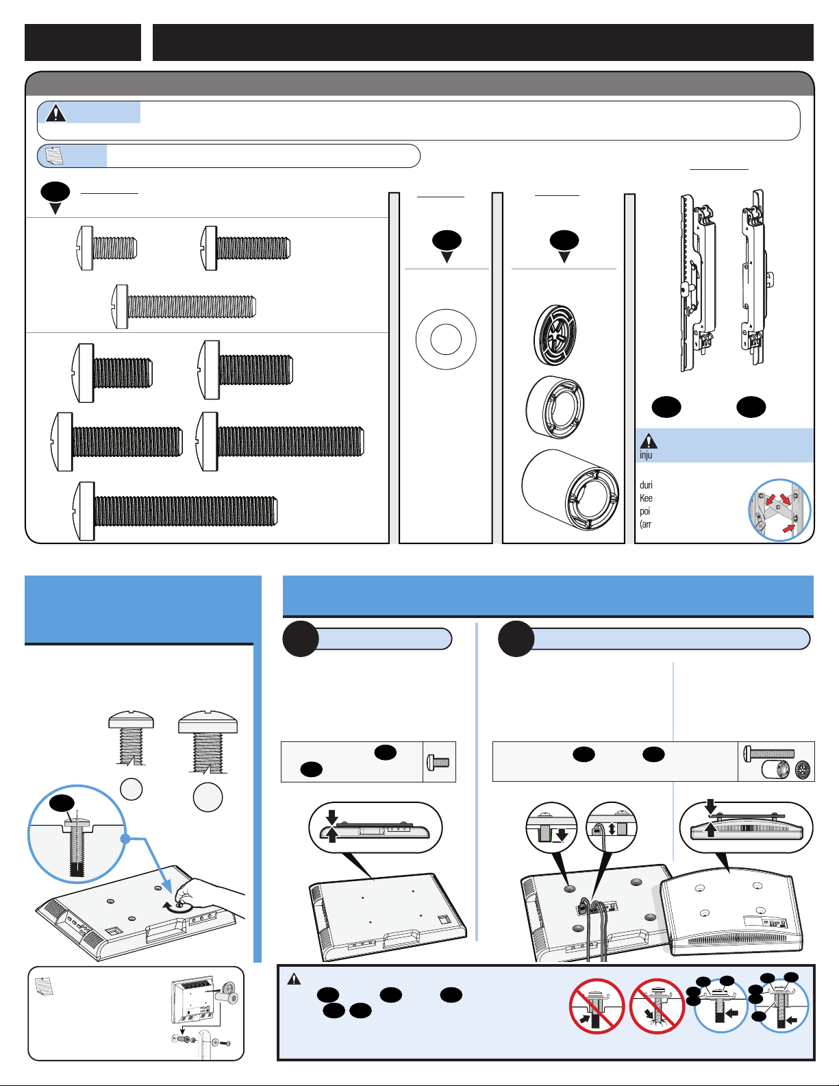
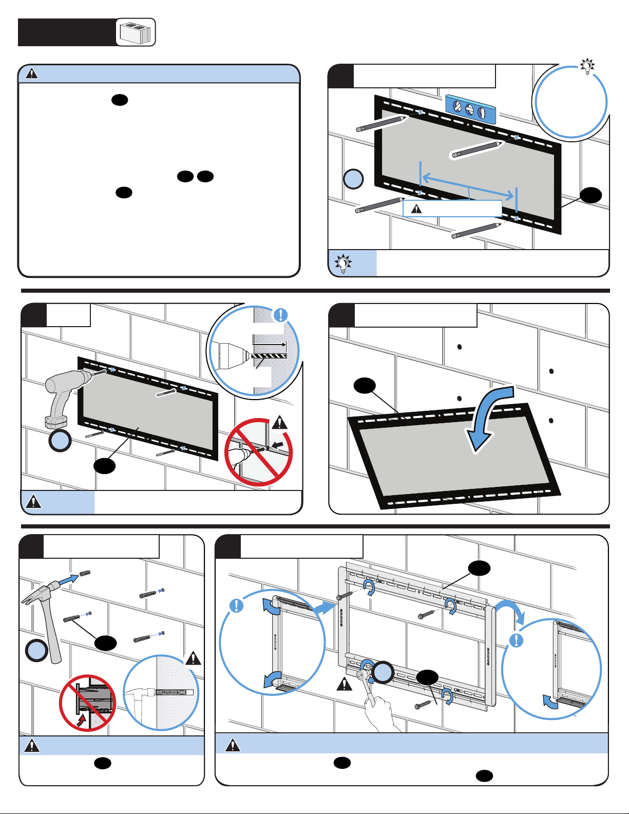
ATTACH TV BRACKET TO TVSTEP 1
CAUTION: Avoid potential personal
injury or property damage!
The TV brackets contain potential pinch points
during operation.
Keep fingers away from pinch
points when retracting the TV.
(arrows)
WARNING: This product contains small items that could be a choking hazard if swallowed. Before starting assembly, verify all parts are included and undamaged. If any parts
are missing or damaged, do not return the damaged item to your dealer; contact Customer Service. Never use damaged parts!
NOTE: Not all hardware included will be used.
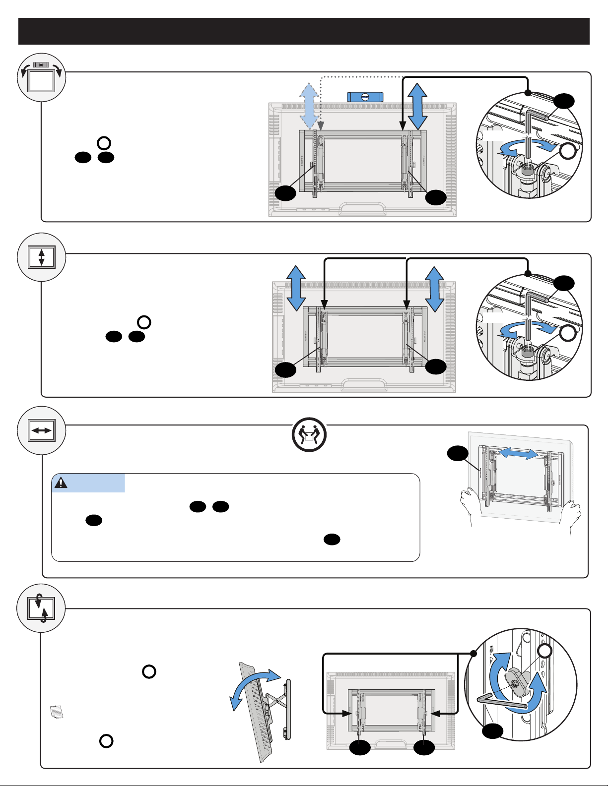
1.1 Select TV
Screw Diameter
1.2 Select TV Screw Length / Spacers
TV Screws
(qty. 4 each) [Only one size fits your TV] Washers
(qty. 4)
Spacers
[If necessary]
(qty. 4 each)
0302
01
M6/M8 M6/M8
M6
M8
(qty. 1)
05
(qty. 1)
04
TV Bracket
03
04 04
05 05
02
02 01
01
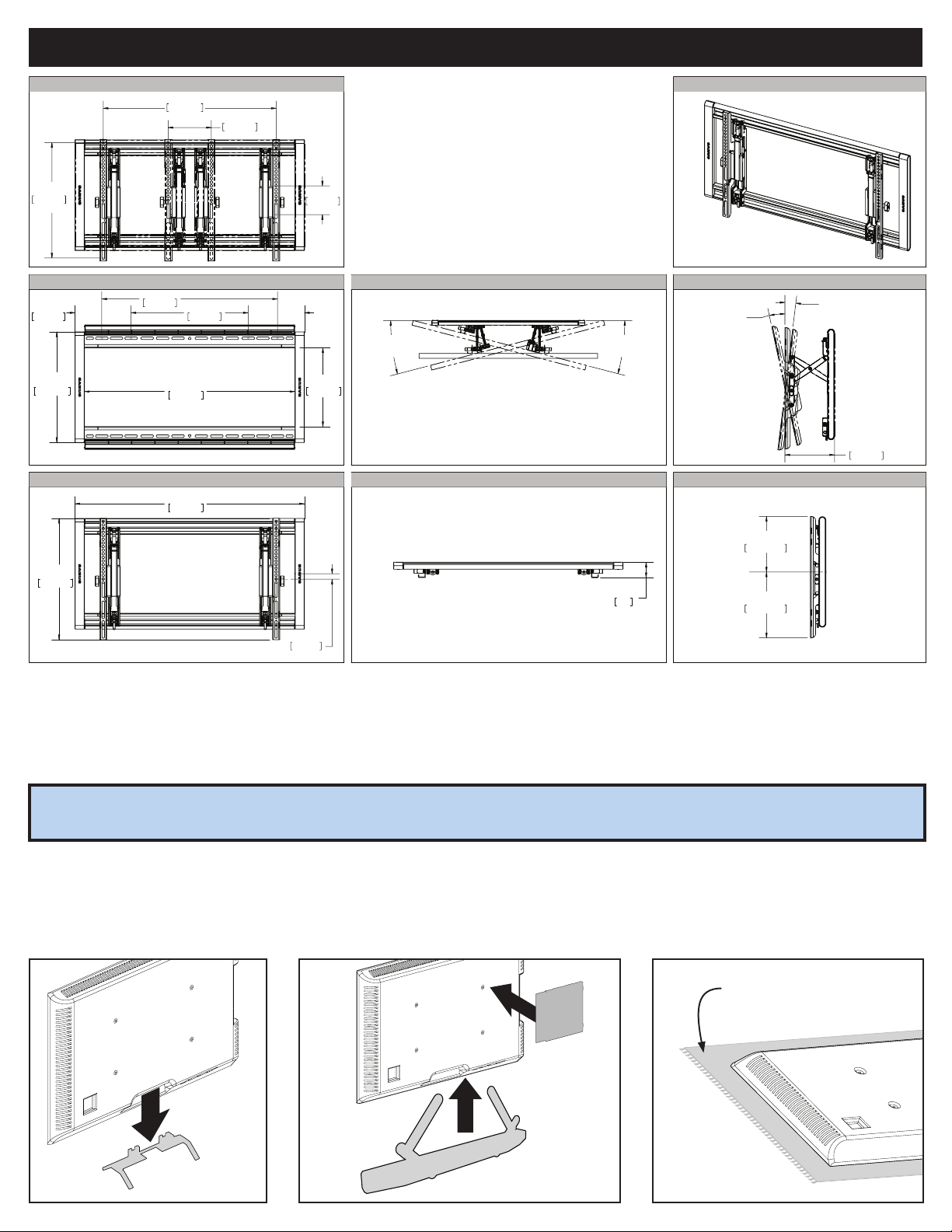
Too Short Too Long Correct
Inset Holes Cables Rounded Back
Only one screw size fits your TV.
M6 M8
• Flat Back TV
[TV brackets
lay flat on your TV]
NO SPACER SPACER NEEDED
• Flat Back TV with
Extra Space Needed
[for deep inset holes
or cable interference]
• Rounded or
Irregular Back TV
[TV brackets NOT
resting flat on your TV]
A B
Use short TV screws 01 .Spac-
ers 03 not needed.
Use long TV screws 01 and spacers 03 to create extra
space between the TV and TV bracket.
01
CAUTION: Verify adequate thread engagement with your
screw 01 , washer 02 , spacer 03 combination AND TV
bracket 04 /05 .
—Too short will not hold your TV.
—Too long will damage your TV.
**
*
NOTE: If your TV included
inset spacers or adapters, use
them UNDER the mount hardware.