manuals.online logo
Brands
  1. Home
  2. •
  3. Brands
  4. •
  5. Sanyo
  6. •
  7. Security Camera
  8. •
  9. Sanyo VCB-3512T User manual

Sanyo VCB-3512T User manual

Other Sanyo Security Camera manuals

Sanyo VCC-HD2100P User manual

Sanyo

Sanyo VCC-HD2100P User manual

Sanyo VCC-9624 User manual

Sanyo

Sanyo VCC-9624 User manual

Sanyo VCC-4110P User manual

Sanyo

Sanyo VCC-4110P User manual

Sanyo VPC-MZ1E User manual

Sanyo

Sanyo VPC-MZ1E User manual

Sanyo VCC-5884E - 1/3" Color CCD DSP High-Resolution... User manual

Sanyo

Sanyo VCC-5884E - 1/3" Color CCD DSP High-Resolution... User manual

Sanyo VCC-9500 User manual

Sanyo

Sanyo VCC-9500 User manual

Sanyo VCC-6585P User manual

Sanyo

Sanyo VCC-6585P User manual

Sanyo VCC-HD4000P User manual

Sanyo

Sanyo VCC-HD4000P User manual

Sanyo VCC-HD4600P User manual

Sanyo

Sanyo VCC-HD4600P User manual

Sanyo VDC-D1185VP User manual

Sanyo

Sanyo VDC-D1185VP User manual

Sanyo VDC-C1024V User manual

Sanyo

Sanyo VDC-C1024V User manual

Sanyo VDC-HD3100P/HD3100 User guide

Sanyo

Sanyo VDC-HD3100P/HD3100 User guide

Sanyo VCC-6592P User manual

Sanyo

Sanyo VCC-6592P User manual

Sanyo Camera Lens User manual

Sanyo

Sanyo Camera Lens User manual

Sanyo VCC-6584E - 1/3" Color CCD DSP High-Resolution... User manual

Sanyo

Sanyo VCC-6584E - 1/3" Color CCD DSP High-Resolution... User manual

Sanyo VCC-XZ200P User manual

Sanyo

Sanyo VCC-XZ200P User manual

Sanyo VCC-N6695P User manual

Sanyo

Sanyo VCC-N6695P User manual

Sanyo VCC-5995P User manual

Sanyo

Sanyo VCC-5995P User manual

Sanyo VCC-XZ600P User manual

Sanyo

Sanyo VCC-XZ600P User manual

Sanyo VCC-4594 User manual

Sanyo

Sanyo VCC-4594 User manual

Sanyo VCC-4790P User manual

Sanyo

Sanyo VCC-4790P User manual

Sanyo VDC-HD3100P User manual

Sanyo

Sanyo VDC-HD3100P User manual

Sanyo VCC-HD5600 - Full HD 1080p Day/Night Pan-Tilt-Zoom... User manual

Sanyo

Sanyo VCC-HD5600 - Full HD 1080p Day/Night Pan-Tilt-Zoom... User manual

Sanyo VCC-MC600P User manual

Sanyo

Sanyo VCC-MC600P User manual

Popular Security Camera manuals by other brands

ADEMCO RapidDome Owners Operating & Installation Guide

ADEMCO

ADEMCO RapidDome Owners Operating & Installation Guide

EverFocus EBA2880 user manual

EverFocus

EverFocus EBA2880 user manual

Honeywell OptiCAM-IR Installation and setup guide

Honeywell

Honeywell OptiCAM-IR Installation and setup guide

Uniq UC-600 user manual

Uniq

Uniq UC-600 user manual

OPTICOM NVD-120-S datasheet

OPTICOM

OPTICOM NVD-120-S datasheet

Steren CCTV-221 instruction manual

Steren

Steren CCTV-221 instruction manual

Arm Electronics C420BCDNVFIR Features

Arm Electronics

Arm Electronics C420BCDNVFIR Features

Eneo PLD-2036PTZ installation guide

Eneo

Eneo PLD-2036PTZ installation guide

Axis AXIS M20 Series installation guide

Axis

Axis AXIS M20 Series installation guide

Panasonic KX-HCM230 operating instructions

Panasonic

Panasonic KX-HCM230 operating instructions

COP-USA CC15NV-SL Specifications

COP-USA

COP-USA CC15NV-SL Specifications

Active Silicon HARRIER H.264 quick start guide

Active Silicon

Active Silicon HARRIER H.264 quick start guide

Motorola Avigilon 1.3C-H5SL-BO1-IR installation guide

Motorola

Motorola Avigilon 1.3C-H5SL-BO1-IR installation guide

INSTEON 2864-232 user manual

INSTEON

INSTEON 2864-232 user manual

Wisenet XNB-6002 quick start guide

Wisenet

Wisenet XNB-6002 quick start guide

Axis M5525-E user manual

Axis

Axis M5525-E user manual

Vitek VTC-IR62NZ922 user guide

Vitek

Vitek VTC-IR62NZ922 user guide

Panasonic WV-SF342 Specifications

Panasonic

Panasonic WV-SF342 Specifications

manuals.online logo
manuals.online logoBrands
  • About & Mission
  • Contact us
  • Privacy Policy
  • Terms and Conditions

Copyright 2025 Manuals.Online. All Rights Reserved.

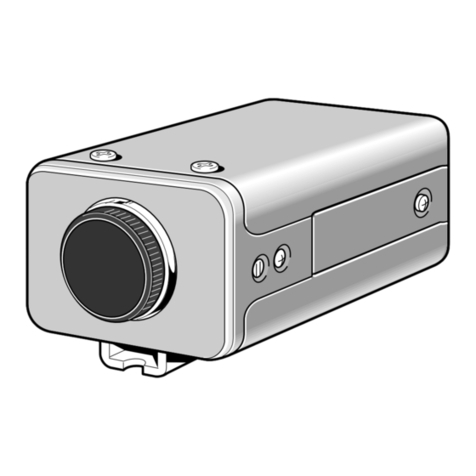
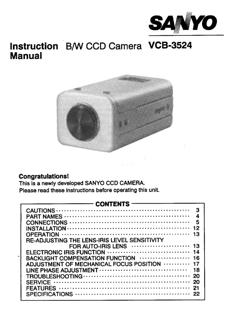
INSTRUCTION MANUAL
B/W CCD Camera
VCB-3512T
About this manual
•Before installing and using the camera, please read this manual carefully. Be sure to
keep it handy for later reference.
L72K2/US2 GB 1998,2,24
SANYO INDUSTRIAL VIDEO
B/W VIDEO CAMERA LIMITED WARRANTY
OBLIGATIONS
Inordertoobtainwarrantyservice,theproductmustbedeliveredtoandpickedupfromanAuthorizedSanyoServiceCenter
attheuser’sexpense,unlessspecificallystatedotherwiseinthiswarranty.ThenamesandaddressesofAuthorizedSanyo
ServiceCentersmaybeobtainedbywritingtoSFSCorporation,SFC’swarrantyadministrator,atanyoftheaddresseslisted
below,orbycalling(toll-free)1-800-421-5013.
NewJerseyOffice
210RiserRoad
LittleFerry,NJ07643
201-641-3000 CaliforniaOffice
1200W.ArtesiaBlvd.
Compton,CA90220
310-537-5830 IllinoisOffice
900N.ArlingtonHeightsRd.
Itasca,IL60143
708-775-1414
THISWARRANTYISVALIDONLYONSANYOPRODUCTSPURCHASEDORRENTEDINTHEUNITEDSTATESOF
AMERICA,EXCLUDINGHAWAIIANDALLU.S.TERRITORIESANDPROTECTORATES.THISWARRANTYAPPLIESONLY
TOTHEORIGINALRETAILUSER.THEORIGINALDATEDBILLOFSALE,SALESSLIPORRENTALAGREEMENTMUSTBE
SUBMITTEDTOTHEAUTHORIZEDSANYOSERVICECENTERATTHETIMEWARRANTYSERVICEISREQUESTED.
SubjecttotheOBLIGATIONSaboveandEXCLUSIONSbelow,SANYOFISHER(USA)CORPORATIONwarrantsthisSANYO
productagainstdefectsinmaterialsandworkmanshipfortheperiodsspecifiedbelow.SFCwillrepairorreplace(atits
option)theproductandanyofitspartswhichfailtoconformtothiswarranty.Thewarrantyperiodcommencesonthedate
theproductwasfirstpurchasedorrentedatretail.
LABOR PARTS IMAGEDEVICE
2YEARS 2YEARS 2YEARS
EXCLUSIONS
Thiswarrantydoesnotcover(A)theadjustmentofcustomer-operatedcontrolsasexplainedintheappropriatemodel’s
instructionmanual,or(B)therepairofanyproductwhoseserialnumberhasbeenaltered,defacedorremoved.
Thiswarrantyshallnotapplytothecabinetorcosmeticparts,antenna,knobs,batteriesorimageburnstoprojectionor
picturetubescausedbyelectronicdevicesorgames.
Thiswarrantydoesnotapplytouncrating,setup,installation,removaloftheproductforrepairorreinstallationoftheproductafterrepair.
ThiswarrantydoesnotapplytorepairsorreplacementsnecessitatedbyanycausebeyondthecontrolofSFCincluding,but
notlimitedto,anymalfunction,defectorfailurecausedbyorresultingfromunauthorizedserviceorparts,improper
maintenance,operationcontrarytofurnishedinstructions,shippingortransitaccidents,modificationorrepairbytheuser,
abuse,misuse,neglect,accident,incorrectpowerlinevoltage,fire,floodorotherActsofGod,ornormalwearandtear.
TheforegoingisinlieuofallotherexpressedwarrantiesandSFCdoesnotassumeorauthorizeanypartytoassumeforit
anyotherobligationorliability.
THEDURATIONOFANYWARRANTIESWHICHMAYBEIMPLIEDBYLAW(INCLUDINGTHEWARRANTIESOF
MERCHANTABILITYANDFITNESS)ISLIMITEDTOTHETERMOFTHISWARRANTY.INNOEVENTSHALLSFCBELIABLE
FORSPECIAL,INCIDENTALORCONSEQUENTIALDAMAGESARISINGFROMOWNERSHIPORUSEOFTHISPRODUCT,
ORFORANYDELAYINTHEPERFORMANCEOFITSOBLIGATIONSUNDERTHISWARRANTYDUETOCAUSESBEYOND
ITSCONTROL.
SOMESTATESDONOTALLOWLIMITATIONSONHOWLONGANIMPLIEDWARRANTYLASTSAND/ORDONOTALLOW
THEEXCLUSIONORLIMITATIONOFCONSEQUENTIALDAMAGES,SOTHEABOVELIMITATIONSANDEXCLUSIONS
MAYNOTAPPLYTOYOU.
THISWARRANTYGIVESYOUSPECIFICLEGALRIGHTS.YOUMAYHAVEOTHERRIGHTS,WHICHVARYFROMSTATETOSTATE.
ATTENTION
Foryourprotectionintheeventoftheftorlossofthisproduct,pleasefillintheinformationbelowforyouownpersonalrecords.
Model No.___________________________________________ Serial No.___________________________________________
(Located on back or bottom side of unit.)
Date of Purchase ____________________________________ Purchase Price _____________________________________
Where Purchased _____________________________________________________________________________________________
L72K2/US2 GB 1998,2,24
14English
Depending on the conditions of use,
installation and environment, please be
sure to make the appropriate settings and
adjustments. If you need help with
installation and/or settings, please consult
your dealer.
CONTENTS
INFORMATION TO USER ..................................2
PRECAUTIONS...................................................3
PARTS NAMES...................................................4
MOUNTING THE LENS......................................6
POWER SOURCE................................................8
CONNECTIONS..................................................9
SETTINGS.........................................................10
TROUBLESHOOTING.......................................12
SPECIFICATIONS .............................................13
ACCESSORIES
1 mount adaptor (5 mm)................ 1 pc.
The mount adaptor must be used to
be able to install a mount lens on the
camera.
2Lens iris plug (4-pin) ........................1 pc.
12
FEATURES
•Built-in interline transfer method 1/2"
D, approx. 410,000 picture elements
•Low smear, anti-blooming, low lag, no
burning and no geometric distortion
using the D solid state image device.
•100% solid state components giving
excellent immunity to shock and
vibration
•Not subject to interference from
magnetic or electrostatic fields
•High sensitivity, minimum required
illumination of 0,07 lux with F1.2 lens
•Horizontal resolution, more than 570 TV
lines
•New backlight compensation function
(Active when using an auto-iris lens)
•Externally adjustable flange back
(mechanical focus)
•Low power consumption and quick start
•12 V D operation
L72K2/US2 GB 1998, 2, 24
English 1
Safety Guard
THIS SYMBOL INDICATES THAT
THERE ARE IMPORTANT
OPERATING AND
MAINTENANCE INSTRUCTIONS
IN THE LITERATURE
ACCOMPANYING THIS UNIT
WARNING:
TO PREVENT THE RISK OF FIRE OR
ELECTRIC SHOCK , DO NOT EXPOSE
THIS APPLIANCE TO RAIN OR
MOISTURE
This installation should be made by a
qualified service person and should
conform to all local codes.
INFORMATION TO USER
For the customers in Canada
This lass B digital apparatus complies
with anadian I ES-003.
Pour la clientèle canadienne
et appareil numerique de la lasse B
est conforme a la norme NMB-003 du
anada.
This equipment has been tested and
found to comply with the limits for a
lass B digital device, pursuant to Part
15 of the F Rules.
These limits are designed to provide
reasonable protection against harmful
interference in a residential installation.
This equipment generates, uses, and
can radiate radio frequency energy and,
if not installed and used in accordance
with the instructions, may cause
harmful interference to radio
communications.
However, there is no guarantee that
interference will not occur in a particular
installation. If this equipment does
cause harmful interference to radio or
television reception, which can be
determined by turning the equipment
off and on, the user is encouraged to
try to correct the interference by one or
more of the following measures:
– Reorient or relocate the receiving
antenna.
– Increase the separation between the
equipment and receiver.
– onnect the equipment into an
outlet on a circuit different from that
to which the receiver is connected.
– onsult the dealer or an experienced
radio/TV technician for help.
This device complies with Part 15 of the
F Rules. Operation is subject to the
following two conditions: (1) This device
may not cause harmful interference,
and (2) this device must accept any
interference received, including
interference that may cause undesired
operation.
hanges or modifications not expressly
approved by Sanyo may void the user’s
authority to operate this camera.
L72K2/US2 GB 1998, 2, 24
2English
PRECAUTIONS
In case of problem
Do not use the camera if smoke or a
strange odour comes from the unit, or if it
seems not to function correctly. Disconnect
the power cord immediately, and consult
your dealer (or a Sanyo Authorized Service
entre).
Do not open or modify
Do not open the cabinet, as it may be
dangerous and cause damage to the unit.
For internal settings and repairs, consult
your dealer (or a Sanyo Authorized Service
entre).
Do not put objects inside the unit
Make sure that no metal objects or
flammable substance get inside the camera.
If used with a foreign object inside, it could
cause a fire, short-circuits or damages.
If water or a liquid gets inside the camera,
disconnect the power cord immediately,
and consult your dealer (or a Sanyo
Authorized Service entre). Be careful to
protect the camera from rain, sea water,
etc.
Be careful when handling the unit
To prevent damages, do not drop the
camera or subject it to strong shock or
vibration.
Install away from electric or
magnetic fields
If installed close to a TV, radio transmitter,
magnet, electric motor, transformer, audio
speakers the magnetic field they generate
will distort the image.
Protect from humidity and dust
To prevent damages to the camera, do not
install it where there is greasy smoke or
steam, where the dampness may get too
high, or where there is a lot of dust.
Protect from high temperatures
Do not install close to stoves, or other heat
generating devices, such as spotlights, etc.,
or where it could be subject to direct
sunlight, as that could cause deformation,
discoloration or other damages.
Be careful when installing close to the
ceiling, in a kitchen or boiler room, as the
temperature may raise to high levels.
Install where the temperature range will
stay between –10˚ and 50˚ .
(no condensation)
Cleaning
•Dirt can be removed from the cabinet
by wiping it with a soft cloth. To
remove stains, wipe with a soft cloth
moistened with a soft detergent
solution and wrung dry, then wipe dry
with dry soft cloth.
•Do not use benzine, thinner or other
chemical product on the cabinet, as that
may cause deformation and paint
peeling. Before using a chemical cloth,
make sure to read all accompanying
instructions. Make sure that no plastic
or rubber material comes in contact
with the cabinet for a long period of
time, as that may cause damage or
paint peeling.
L72K2/US2 GB 1998, 2, 24
English 3
PARTS NAMES
1Video output connector (VIDEO OUT: BNC type)
onnect this connector to a device such as a V R or monitor
with a VIDEO IN connector.
212 V DC input terminal (12 V DC, GND)
3External sync composite video signal input connector
(VS IN: BNC type)
onnect to this connector the synchronizing signal output
from a synchronizing signal device or the composite signal of
a video distributor.
4Power indicator (POWER)
omes on when the power to the camera is on.
5Lens mount cap
The cap is installed to protect the lens mount section.
Remove the lens mount cap before installing a lens (sold
separately).
6Camera installation bracket
The bracket can be fixed at the top or bottom of the
camera. When fixing the bracket, be sure to use the longer
screws and install the shorter screws on the opposite side to
seal the openings.
CAUTION:
When installing the camera support, select a location
that can support the total weight of the camera and
accessories
1232
1
6
5
1
2
4
3
1Shorter screws: M3 x 4
2Longer screws: M3 x 6
3Camera mounting
screw hole: 1/4"-20
UNC
L72K2/US2 GB 1998, 2, 24
4English
PARTS NAMES
8Lens iris output connector (4 pin)
This 4-pin connector is used to send the D control signal
and power supply to an auto-iris type lens.
9Camera setup section (under the cover)
This unit factory settings are as indicated below. These
settings are for when using a 1/2 inch S mount DC
(without EE internal amplifier) type lens. However, if due to
installation conditions or environment the settings may need
to be modified for best results (see "SETTINGS"). To access
the controls, remove the cover fixing screw, then remove the
cover.
Control name Position
aHigh speed electronic shutter
switches (E S ) All OFF: 1/60 sec
bElectronic iris (EI)/
Backlight compensation (BLC)
switch
OFF
c
FFlange-back adjustment screw (FLANGE BACK ADJ )
GFlange-back lock screw (FLANGE BACK LOCK)
Flange-back adjustment
If the pick-up surface is not correctly positioned with relation
to the lens focal point, the picture will be out of focus (in
particular when using auto-iris power zoom lenses, sold
separately). If that is the case, adjust the flange-back position
as described below.
1Using a + screwdriver, loosen the FLANGE BACK LOCK
screw (M2:+).
Set the zoom lens to the maximum telephoto position,
set the focus using the focus ring on the lens.
2Set the zoom lens to the maximum wide angle position,
set the focus using the FLANGE BACK ADJ screw.
3Repeat steps 2 and 3, until the image stays in focus when
changing from a telephoto shot to a wide angle shot.
When the setting is complete, tighten the FLANGE
BACK LOCK screw.
1G
F
1
3
LOCK
2
ADJ.
MOUNTING THE LENS
Check the lens mount
Do not use a lens if the length “L” is more than 7 mm.
That may damage the camera and prevent proper
installation.
Installation of a DC type auto-iris lens (sold
separately)
A 1/3 inch S mount type lens without EE amplifier circuit
that only uses a D power source. This camera can receive
(the A I LENS switch to the D type) a S mount type lens
without the need of an adaptor.
If the lens plug shape or wiring does not correspond, please
install the supplied plug as indicated in the pin layout table.
L
L72K2/US2 GB 1998, 2, 24
6English
MOUNTING THE LENS
Installation of a VIDEO type auto-iris lens
(sold separately)
A 1/2 or 2/3 inch mount type lens with EE amplifier circuit
that uses the video signal and a D power source.
1Remove the lens mount cap.
2Attach the supplied C mount adaptor (A) to the
auto-iris lens (B), then install the assembly on the camera.
3onnect the lens plug to the LENS connector on the side
of the camera.
If the lens plug shape or wiring does not correspond to
the specifications below, connect the supplied plug as
indicated.
•When using lenses from other makers, make sure that
the pins connections in the plug correspond to the
ones of the camera.
Refer to the lens specifications to check the pins
connections in the plug.
•If they are different than indicated, remove the original
plug and connect the supplied plug according to the
diagram.
4Set the A I LENS switch in the camera setup section to
the VIDEO position.
Pin layout
DC type lenses VIDEO type lenses
1Brake coil (–) +12 V D (50 mA max.)
2Brake coil (+) Not used
3Drive coil (+) Video output (1.0 Vp-p, high
impedance)
4Drive coil (–) Ground (for video signal and D
power)
2 (A) (B)
3
31
2
4
DC
VIDEO
4
L72K2/US2 GB 1998, 2, 24
English 7
Compatible auto-iris lenses
1/2 inch Sanyo DC type lens 1/2 or 2/3 inch VIDEO type lens
V L- S12GY: Standard angle, f= 12 mm Standard angle, f= 9 mm
V L- S6GY: Wide angle, f= 6 mm Telephoto angle, f= 12 mm
V L- S3GY: Ultra-wide angle, f= 3.7 mm More telephoto angle, f= 16 mm
If using a VIDEO type auto-iris lens
•Set the ALC and LEVEL controls on the lens to adjust the iris. Normally the ALC volume
should be turned all the way to Av (Average).
•Depending on the type of lens used, the lens may not perform properly. In such a case,
adjust the LEVEL volume on the lens casing to correct.
POWER SOURCE
onnect D 12V power supply to 12V DC input terminal on
the camera.
N : non connect
NC
+–
L72K2/US2 GB 1998, 2, 24
8English