Sapphire Audio HOSS 700 User manual

49-075D 2011-09 Warranty 49-071 1 Sapphire Scientific
HOSS 700 Rotary Cleaning Tool
Owner’s Manual
Sapphire Scientific • Sales: 866-445-3030 • Technical Support: 866-445-3030.
Congratulations on your purchase of a HOSS 700 Rotary Cleaning Tool from Sap-
phire! With a durable design and innovative cleaning features, the HOSS 700 makes
carpet cleaning easier, more effective and more profitable.
Patents pending
READ AND SAVE THESE INSTRUCTIONS
SAFETY INSTRUCTIONS
WARNING! Electric shock hazard, rotating parts, hot
surface hazards. Unplug unit before opening cover
for cleaning or servicing. Unit must be properly
grounded.
•Inspect the power cord before use. If cord is dam-
aged, do not use. Always grasp the plug (not the
cord) to unplug.
•The unit must be operated on a 110V/60Hz circuit.
•Keep motor and wiring dry.
•Do not operate in standing water
•Do not operate in rain or snow. If electrical compo-
nents become wet, allow them to dry before using.
•Do not attempt to repair the unit. For technical sup-
port, call Sapphire at 866-445-3030.
NOTICE: Protect from freezing during storage and
transport. Damage caused by freezing is not covered by
the product warranty.
INTRODUCTION
The HOSS 700 Rotary Cleaning Tool greatly improves
cleaning performance and efficiency on a wide variety of
carpet types.
•High-flow solution orifices and high efficiency va-
cuum plates
•½ HP 1725 RPM motor
•Sealed low-maintenance gear box
•6 in. non-scuffing wheels for easy transport
•Fully adjustable handle for maximum operator com-
fort and control
WARNING

49-075D 2011-09 Warranty 49-071 2 Sapphire Scientific
PARTS IDENTIFICATION
IMPORTANT: The HOSS 700 is shipped with the handle and electrical cord unat-
tached. Attach these items before using. See “Handle Installation Instructions,”
p. 4.
Figure 1
A. Handles.
B. Solution control lever. Squeeze to start solution flow.
C. Motor control lever. Squeeze to start head rotation.
D. Solution line inlet connection. Attach to solution line coming from solution pump.
E. Connection for rotary head solution line.Factory installed.
F. Vacuum hose attachment. Connect to 2 in. vacuum hose, or use adaptor for 1½ in. hose.
G. Power cord connection. Use with a heavy duty extension cord with suitable amp rating.
H. Inline solution filter. Dissassemble for cleaning. See “Clean Inline Filter,” p. 8. A flow control orifice, when in-
stalled, is located here. See “Cleaning and Operational Tips,” p. 8.
J. Handle height adjustment slot.Loosen knob to raise or lower handle. Tighten firmly after adjustment.
Figure 2
K. Transport wheels. Tip unit back on wheels to easily move unit from room to room.
L. Vacuum Inlet Cleanout Cap. Lift out for quick cleaning.
M. Carry handle. Use only when handle is in upright position and locked into position.
A
J
F
G
E
C
B
M
L
K
D
H
Fig. 1
Fig. 2

49-075D 2011-09 Warranty 49-071 3 Sapphire Scientific
PARTS IDENTIFICATION (cont.)
Figure 3
N. Solution orifices (×5). May be removed with a ⅜in. socket or nut driver for cleaning or replacement. Align rotor
with Access Notch P in housing to access each orifice.
Q. Vacuum feet Q (×5). May be removed for cleaning or replacement.
Fig. 3
Q
N
P

49-075D 2011-09 Warranty 49-071 4 Sapphire Scientific
HOSS 700 Assembly Instructions
IMPORTANT! Complete these steps before using the HOSS 700 for the first time.
Tools required:
•Pliers
•Phillips head screwdriver
•¼ in. ratchet
•Two 9/16 in. wrenches.
1. Slide the handle brace to the center of the axle and
attach E clip Aretaining ring to the axle.
Tip: Pliers may be needed to compress washer be-
tween bar and pre-installed E clip.
2. Attach handle assembly using bolts B, metal wash-
ers C, nylon washers Dand lock nuts Eas shown. At-
tach both sides.
B C D D C E
A

49-075D 2011-09 Warranty 49-071 5 Sapphire Scientific
3. Attach handle brace to handle assembly. Place flat
washer Hand rubber washer Gon the threaded shaft
of knob Fas shown. Insert knob Fthrough slot in han-
dle and thread into T-bracket J.
4. Attach the blue solution line Kto the top of vacuum
inlet cap M.
K
M
F
H
G
J

49-075D 2011-09 Warranty 49-071 6 Sapphire Scientific
5. Place nut, rubber gasket as shown over the end of
the power cord. Insert the three wires through the re-
tainer ring one at a time, starting with the black wire,
then the the white wire, then the green wire. After in-
serting the wires, reseat the rubber gasket insider the
retainer ring.
6. Loosen both junction cover plate screws and rotate
the plate away from the junction cavity. Insert end of
cord through threaded hole in side of motor, starting
with the black wire, then the white wire, then the green
wire. Connect black-to-black and white-to-white with
the blade connectors. Attach the green ground wire to
the ground screw.
7. Thread strain relief nut over fitting and tighted.
Carefully coil wires and tuck into junction cavity and
rotate junction cover plate back into place. Tighten
screws.
8. Attach the cover plate Owith the two sets of screws
Pand spacers R.
O
P
R

49-075D 2011-09 Warranty 49-071 7 Sapphire Scientific
9. IMPORTANT: Replace temporary gear box plug (S)
with vent plug provided.
SETUP
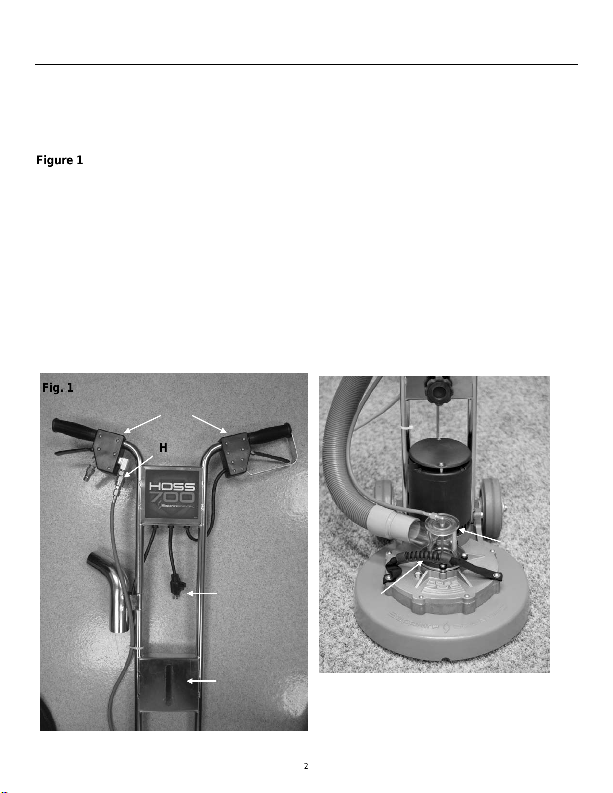
1. Adjust handle height for operator comfort. Loosen
black knob, move handle up or down to desired height,
and retighten. See Fig. 1.
TIP: To maximize control and operator comfort, position
the handles at hip height.
2. Attach vacuum hose to vacuum outlet. The HOSS 700
is fitted with a 2 in. O.D. vacuum outlet, Fig. 1, F.
3. Attach solution hose to quick-connect fitting, Fig. 1, D.
4. Connect to a 115V/15 amp supply power source (Fig.
1, G), using a suitable extension cord. Cords up to 50 ft.
long should be at least 14 gauge 3-wire; longer cords, up
to 100 ft. maximum, should be 12 gauge 3-wire..
WARNING: Electrical shock hazard. Unit must be prop-
erly grounded. Do not remove grounding prong or oth-
erwise alter the grounding system.
OPERATION
WARNING:Rotating parts. Keep hands, feet and all
cords and hoses clear. Make sure the area to be
cleaned is free from obstructions and place power cords
and hoses well away from the unit.
1. Turn on the carpet cleaning extractor vacuum and
solution pump.
2. Start the flow of solution first. Grasp handles firmly
and squeeze right trigger (Fig. 1, B).
3. Balance the unit with the head flat on the carpet. Then
squeeze left trigger (Fig. 1, C) to start rotary head.
WARNING:Rotary head starts abruptly. Be prepared to
raise or lower the handle to control the unit. Only slight
adjustments are required.
Controlling the unit
•To move to the right, LIFT the handle with both
hands slightly.
•To move to the left, LOWER the handle with both
hands slightly.
Tip: Only small adjustments in handle position are
needed to control the unit. If you are unfamiliar with ma-
neuvering this cleaning tool, practice first in an open and
unobstructed area.
Tip: Do not tip the unit to the left or right, as this will im-
pair vacuum performance and make the unit difficult to
control.
Cleaning and Operational Tips
Do not operate the HOSS 700 on dry carpets, as this
may damage carpet fibers.
Do not operate the HOSS 700 on hard surfaces, as
this may damage the vacuum heads and/or floor surfac-
es.
For best results, vacuum the carpet thoroughly before
using the HOSS 700.
Adjust solution flow. The flow of solution can be cus-
tomized to soiling conditions and type of cleaning
equipment used. To provide maximum solution flow, the
HOSS is shipped without a restrictor installed. The Hoss
700 is supplied with .048, .052, and .057 in. flow-
restricting orifices. Customers who wish to restrict flow
may add one of the restrictors provided to the inline filter
assembly (Fig. 1, H). To install a restrictor, disassemble
the in-line filter, place the restrictor in position between
the filter screen and the nut, and reassemble.
For best results, always groom the carpet after clean-
ing.
Always establish adequate drying conditions after
cleaning.
S

49-075D 2011-09 Warranty 49-071 8 Sapphire Scientific
MAINTENANCE
WARNING: Electrical shock hazard. Unplug unit be-
fore performing any maintenance task.
Before each use
Inspect the electrical cord for damage. Look for fray-
ing, cuts, etc. Do not use the unit if you find any damage.
Inspect vacuum hoses, solution lines and all fittings
for proper function. Repair or replace as needed.
Check manifolds for proper flow. With solution hose
attached and pressurized, lay unit on its side and briefly
squeeze the solution control lever. Solution should flow
freely and equally from each manifold. If flow is reduced
from any manifold, inspect for blockage. Remove the
manifold, and with a sharp pointed object, clean the ori-
fices. Take care not to damage the orifices.
After each use
Rinse rotary head clean.
Clear vacuum inlet. Remove the vacuum inlet cap from
the vacuum inlet housing and remove any debris. For
best results, keep unit on the vacuum while withdrawing
the inlet cap. Replace cap securely when finished.
Inspect rotary head and vacuum feet for damage.
Replace worn or damaged parts as needed.
Monthly
Clean exterior housing. To maintain appearance, wipe
exterior surfaces with clean with a damp cloth.
Check solution valve.Check for leaks and replace
seals as necessary.
Check orifice and inline filter screen.Loosen the
strainer assembly nut (Fig. 1, H) and remove the orifice,
strainer and strainer washer. Rinse these items in clean
water and reassemble. Take care not to over-tighten the
strainer assembly nut.
Check gearbox oil levels. Remove vented gear case
plug (S). While looking into vent plug hole, tilt unit back
onto its wheels to allow rotary head to be turned. Turn
the head until vent plug hole is aligned with the hole in
the gear web. Now place the unit flat on floor or table
and insert a screwdriver or similar tool to gauge the oil
level. If the oil level is less than ⅛in. (.3 cm), add
Sapphire gear oil (part number 13-053). Do not overfill.
Reinstall vent plug when finished.
As needed
Lubricate the solution line quick-connect couplings
(Fig. 1, D, E) with a small amount of rust-inhibiting oil
such as LPS-3.
Clean inline strainer (Fig. 1, H) when solution flow is
visibly reduced. To clean the filter, loosen the strainer
assembly nut, and remove the strainer and strainer
washer. Rinse these items in clean water and reassem-
ble the strainer. It is not normally necessary to replace
the inline filter element. Be sure to include the nylon
washer when reassembling, and take care not to over-
tighten the strainer assembly nut.
To maintain appearance, wipe exterior surfaces with a
damp cloth.
TRANSPORT AND STORAGE
NOTICE: Handle the unit carefully. Do not drop, or place
the unit where it could fall. Rough treatment can damage
this equipment and may create a hazardous condition or
void warranty.
1. Do not expose electrical components to moisture
when transporting in uncovered vehicles.
2. Store and transport securely to avoid any damaging
impact to internal parts.
3. Protect from freezing. Store unit in heated area.

49-075D 2011-09 Warranty 49-071 9 Sapphire Scientific
TROUBLESHOOTING
FAULT CAUSE SOLUTION
Unit does not oper-
ate No power to machine. Supply circuit
breaker tripped. Reset supply circuit breaker.
Solution leaks at
trigger control valve. Valve seal has failed. Install valve rebuilt kit.
Poor vacuum per-
formance on carpet.
1. Uptake tube clogged with debris
2. Vacuum slot feet gouged or damaged
3. Vacuum inlet clogged
1. Remove lower end and remove obstruction
2. Replace damaged vacuum slot feet
3. Remove vacuum inlet cap and remove debris
Inadequate solution
output
1. Plugged strainer or orifice
2. Incorrect orifice installed
3. Manifolds plugged or damaged
1. Rinse strainer and/or orifice clean
2. Install correct orifice
3. Clean manifolds; replace any damaged manifolds
If the problem you are experiencing is not listed here, call the Sapphire Service Department
at 800-932-3030. Contact your Sapphire distributor for replacement parts and rebuild kits.
WARRANTY
Warranty information is available from your dealer or at
www.sapphirescientific.com.
Warranty registration
Visit warranty.sapphirescientific.com to register your
purchase. Registration allows us to better assist you with
using, maintaining or servicing your equipment, as well
as to contact you in case we have important safety in-
formation concerning your Sapphire Scientific product. If
you determine service is required, have your equipment
model, serial number and original proof of purchase
available and call your distributor for assistance with ob-
taining a return material authorization (RMA).
CONTACT
Sapphire Scientific
2604 Liberator • Prescott, AZ 86301
Sales: 866-445-3030 • Technical Support: 866-445-3030
HOSS 700 SPECIFICATIONS
Model HOSS 700 Rotary Cleaning Tool
Cleaning width 15 in. | 38 cm diameter head
Use weight 68 lbs. | 31 kg
Power 110V / 60Hz
Motor ½ HP 1725 RPM
Construction Lightweight machined aluminum gear box.
Stainless steel handle. 6 in. non-scuffing
wheels.
Rotary system Gear-driven rotor with five replaceable
long life floating heads.
Vacuum system 2 in. tube with clear view vacuum inlet cap.
Specifications are subject to change without notice. Some values
may be approximate.

49-075D 2011-09 Warranty 49-071 10 Sapphire Scientific
PARTS DIAGRAMS
Wiring Schematic

49-075D 2011-09 Warranty 49-071 11 Sapphire Scientific
Handle Assembly

49-075D 2011-09 Warranty 49-071 12 Sapphire Scientific
Trigger Valve Assembly

49-075D 2011-09 Warranty 49-071 13 Sapphire Scientific
Drive Head Assembly

49-075D 2011-09 Warranty 49-071 14 Sapphire Scientific
Vacuum Head Assembly

49-075D 2011-09 Warranty 49-071 15 Sapphire Scientific
Vacuum Head Assembly: Tube Length Detail

49-075D 2011-09 Warranty 49-071 16 Sapphire Scientific
PURCHASE
Purchase date: ________________________
Serial number: ________________________
Distributor: ________________________ Tel. _________________________
MAINTENANCE
DATE SERVICE PERFORMED PERFORMED BY
Other manuals for HOSS 700
2
Table of contents
Other Sapphire Audio Cleaning Equipment manuals
Popular Cleaning Equipment manuals by other brands

BÖWE
BÖWE M21 instruction manual

P.Lindberg
P.Lindberg 9063194 Original manual

HydraMaster
HydraMaster DriMaster HiFlo owner's manual

Vaportek
Vaportek Restorator 90-5000 Use and Operating Instructions

Kärcher
Kärcher Battery Power+ Fast Charger 18/60 manual

GEISMAR
GEISMAR BRV Operation & maintenance instructions