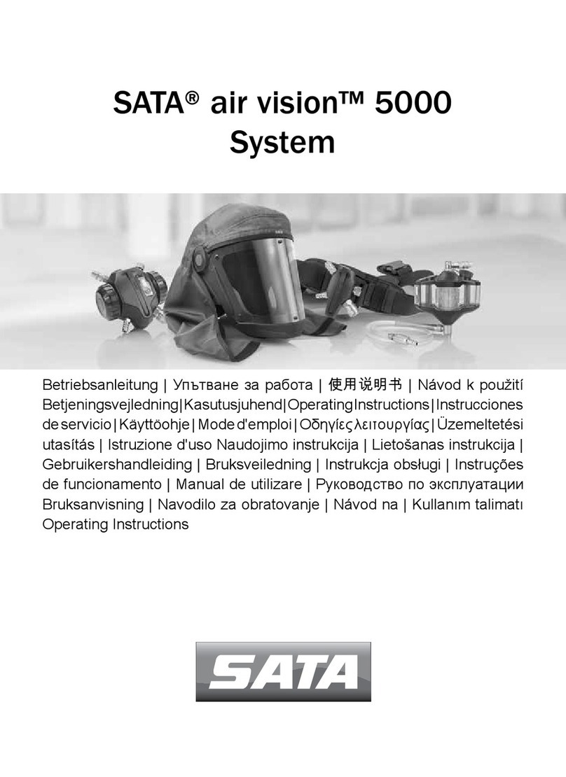
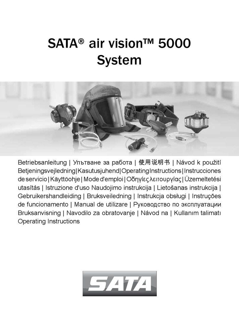
SATA air vision 5000 User manual

SATA® air vision™ 5000
system NIOSH
Betriebsanleitung
Operating Instructions
Mode d'emploi
Instrucciones de servicio

THIS RESPIRATOR IS APPROVED ONLY IN THE FOLLOWING CONFIGURATIONS:
1005562
208421
1022053
213017
221853
209403
1000265
1004556
214759
676010
679010
676015
679015
676020
679020
676025
679025
676035
679035
676050
679050
676075
679075
676100
679100
19C-0533
SA / CF
X X X X X X X X X X X X X X X X X X X X X X X X X A B C D E J
M N O S
1. PROTECTION
2. CAUTION AND LIMITATIONS
A - Not for use in atmospheres containing less than 19.5 percent oxygen.
B -
C -
Do not exceed maximum use concentrations established by regulatory standards.
D -
E - Use only the pressure ranges and hose lengths specified in the User’s Instructions.
J - Failure to properly use and maintain this product could result in injury or death.
M -
N -
O -
S -
Alternate
Belt
Tel. 49-07154-811-255
Fax 49-07154-811-193
Germany
D-70806 Kornwestheim
Domertalstaße 20
Accessories
10 ft
SATA GmbH & Co. KG
TC#
PROTECTION¹
SA=Supplied Air / CF = Continuous flow
Not for use in atmospheres immediately dangerous to life or health.
Air-line respirators can be used only when the respirators are supplied with respirable air meeting the requirements of CGA G-7. Grade D
or high quality.
All approved respirators shall be selected, fitted, used, and maintained in accordance with MSHA, OSHA, and other applicable regulations.
Never substitute, modify, add, or omit parts. Use only exact replacement parts in the configuration as specified by the manufacturer.
Refer to User’s Instructions, and/or maintenance manuals for information on use and maintenance
of these respirators.
Special or critical User’s Instructions and/or use limitations apply. Refer to User’s Instructions before donning.
TYPE C CONTINUOUS FLOW SUPPLIED-AIR RESPIRATOR
Protective respirator equipment family PART. No. 1012301
Alternate Hoses
Facepiece /
Hood or
Helmet
Alternate
Flow
Regulator Caution
and
Limitations²
75 ft 100 ft15 ft 20 ft 25 ft 35 ft 50 ft
Rev: D Date:Febr/26/2021

[0]


5
US
Operating Instructions for SATA Breathing Protection Equipment Operating Instructions for SATA Breathing Protection Equipment
Table of Contents
[Original language: Ger-
man]
1. General Information.................5
2. Safety Instructions.................13
3. Safety Gear ...........................15
4. Intended Use.........................15
5. Technical Data.......................15
6. Breathing Protection Equipment
Scope of Delivery ..................15
7. System Overview ..................16
8. Description of Breathing
Protection Equipment............ 16
9. How to use the breathing
protection hood......................19
10. Maintenance and Repair to
Breathing Protection Hood ....22
11. Operation of Air Regulator..... 24
12. Maintenance and Repair to Air
Regulator...............................26
13. Operatingtheairhumidier ...26
14. Maintenance and Repair of Air
Humidier ..............................29
15. Operating the air warmer/
cooler.....................................30
16. Maintenance and Repair of Air
Warmer/Cooler ......................32
17. Use of Belt Unit .....................32
18. Maintenance and Repair to Belt
Unit........................................32
19. Service, Care and Storage ....32
20. Troubleshooting.....................32
21. Service and Parts ..................33
1. General Information
1.1. Introduction
These User’s Instructions contain
important information on how to
use the breathing protection equip-
ment, which comprises the SATA
air vision 5000 breathing protection
hood, the SATA air regulator, the al-
ternative air regulator with activated
carbonlterSATAaircarbonregu-
lator with optional SATA air warmer
carbon,theSATAairhumidier,
the standalone SATA air warmer /
cooler and the SATA air regulator
belt. They also describe operation,
care, maintenance, cleaning, warn-
ings and error messages as well as
troubleshooting.
Read first!
Read these User’s Instructions
thoroughly and carefully before
using the breathing protection
equipment. Always observe
safety precautions and hazard
warnings!
Always keep these operating in-
structions with the breathing pro-
tection equipment or at a location
accessible to everyone at any time.
1.2. Target group
These operating instructions are intend-
ed for
■Skilled personnel in the painting
trade.
■Personnel trained for painting work in
industrial and trade shops.
[US | CDN] Operating Instructions | US-english

6
US
Operating Instructions for SATA Breathing Protection Equipment
1.3. Cautions and Limita-
tions
A - Not for use in atmospheres
containing less than 19.5 per-
cent oxygen.
B - Not for use in atmospheres
immediately dangerous to life
or health.
C - Do not exceed maximum use
concentrations established by
regulatory standards.
D - Air-line respirators can be
used only when the respirators
are supplied with respirable
air meeting the requirements
of CGA G-7. Grade D or high
quality.
E - Use only the pressure ranges
andhoselengthsspeciedin
the User’s Instructions.
J - Failure to properly use and
maintain this product could
result in injury or death.
M - All approved respirators shall
beselected,tted,used,and
maintained in accordance with
MSHA, OSHA, and other appli-
cable regulations.
N - Never substitute, modify, add,
or omit parts. Use only exact
replacement parts in the con-
gurationasspeciedbythe
manufacturer.
O - Refer to User’s Instructions,
and/or maintenance manuals
for information on use and
maintenance of these respira-
tors.
S - Special or critical User’s In-
structions and/or use limitations
apply. Refer to User’s Instruc-
tions before donning.
1.4. S-Special or Critical Us-
er‘s instructions
General technical data
Description Unit
Max. operating pres-
sure
125 psi
(8.6 bar)
Burst pressure for
pressure hose to air
regulator
1450 psi
(100 bar)
Minimum required
owrate
(for use in Europe.
When pressure drops
below 5.3 cfm (150
Nl/min) an accous-
tic warning signal
sounds)
6.0 cfm
(170 Nl/
Min)
Storage temperature -4 -
+140°F
(-20 -
+60°C)
Operating tempera-
ture
+41 -
+140°F
(+5 -
+60°C)
Operating tempera-
ture with SATA air
warmer
+41 -
+95°F
(+5 -
+35°C)
Operating tempera-
ture with SATA air
cooler
+68 -
+140°F
(+20 -
+60°C)
Max. hose length 100 ft
(30.5 m)

7
US
Operating Instructions for SATA Breathing Protection Equipment Operating Instructions for SATA Breathing Protection Equipment
Description Unit
Max. noise level 74 dB (A)
Weight of breathing
protection hood
34.4 oz
(975 g)
Weight of air regu-
lator
8.2 oz
(233 g)
Weight of air regulator with active
carbonlter
without air warmer 19.1 oz
(541 g)
with air warmer 20.4 oz
(577 g)
Weight of air humidi-
er(empty)
16.3 oz
(462 g)
Weight of air warmer/
cooler
12.2 oz
(345 g)
Description Unit
Weight of belt 8.4 oz
(239 g)
Danger!
Operating the breathing protec-
tionequipmentwiththeairow
rate set incorrectly is prohibited.
Thiscanmakebreathingdifcult.
→Verifytheproperconditionof
all components in use.
→Adjusttherequiredairow
rate so that the indicator on the
pressure gauge [15-1] is in the
green zone [15-2].
System combination
Notice!
air regulator (regulator
fully opened)
air cooler / warmer (regu-
lator fully opened)
Inlet pres-
sure filter
unit (psi)
It is not permissi-
ble to extend these
hoses or combine
them with one
another.
10 ft.
15 ft.
20 ft.
25 ft.
35 ft.
50 ft.
75 ft.
100 ft.
min max
x x 18.9 40.6
x x 20.3 42.0
x x 20.3 43.5
x x 20.3 44.9
1. SATA air vision 5000 x x 20.3 44.9
2. SATA air regulator x x 21.8 47.8
x x 23.2 50.7
x x 24.7 55.1

8
US
Operating Instructions for SATA Breathing Protection Equipment
System combination
Notice!
air regulator (regulator
fully opened)
air cooler / warmer (regu-
lator fully opened)
Inlet pres-
sure filter
unit (psi)
It is not permissi-
ble to extend these
hoses or combine
them with one
another.
10 ft.
15 ft.
20 ft.
25 ft.
35 ft.
50 ft.
75 ft.
100 ft.
min max
x x 24.7 40.6
x x 24.7 42.0
x x 26.1 42.0
x x 26.1 42.0
1. SATA air vision 5000 x x 26.1 42.0
2. SATA air regulator x x 27.6 43.5
3.SATAairhumidier x x 29.0 47.8
x x 30.5 50.7
x x x 76.9 124.7
x x x 76.9 124.7
x x x 76.9 124.7
x x x 78.3 124.7
1. SATA air vision 5000 x x x 78.3 124.7
2. SATA air regulator x x x 78.3 124.7
3. SATA air cooler x x x 79.8 124.7
x x x 82.7 124.7
x x x 76.9 124.7
x x x 78.3 124.7
x x x 78.3 124.7
x x x 78.3 124.7
1. SATA air vision 5000 x x x 79.8 124.7
2. SATA air regulator x x x 79.8 124.7
3. SATA air warmer x x x 82.7 124.7
x x x 82.7 124.7

9
US
Operating Instructions for SATA Breathing Protection Equipment Operating Instructions for SATA Breathing Protection Equipment
System combination
Notice!
air regulator (regulator
fully opened)
air cooler / warmer (regu-
lator fully opened)
Inlet pres-
sure filter
unit (psi)
It is not permissi-
ble to extend these
hoses or combine
them with one
another.
10 ft.
15 ft.
20 ft.
25 ft.
35 ft.
50 ft.
75 ft.
100 ft.
min max
x x x 84.1 124.7
x x x 85.6 124.7
x x x 85.6 124.7
x x x 85.6 124.7
1. SATA air vision 5000 x x x 87.0 124.7
2. SATA air regulator x x x 87.0 124.7
3. SATA air cooler x x x 88.5 124.7
4.SATAairhumidier x x x 88.5 124.7
x x x 85.6 124.7
x x x 85.6 124.7
x x x 85.6 124.7
x x x 85.6 124.7
1. SATA air vision 5000 x x x 87.0 124.7
2. SATA air regulator x x x 87.0 124.7
3. SATA air warmer x x x 89.9 124.7
4.SATAairhumidier x x x 89.9 124.7
x x 21.8 47.8
x x 21.8 49.3
x x 21.8 50.7
x x 23.2 50.7
1. SATA air vision 5000 x x 23.2 52.2
2. SATA air carbon regulator x x 24.7 52.2
x x 26.1 58.0
x x 27.6 60.9

10
US
Operating Instructions for SATA Breathing Protection Equipment
System combination
Notice!
air regulator (regulator
fully opened)
air cooler / warmer (regu-
lator fully opened)
Inlet pres-
sure filter
unit (psi)
It is not permissi-
ble to extend these
hoses or combine
them with one
another.
10 ft.
15 ft.
20 ft.
25 ft.
35 ft.
50 ft.
75 ft.
100 ft.
min max
x x 26.1 43.5
x x 26.1 44.9
x x 27.6 44.9
x x 27.6 44.9
1. SATA air vision 5000 x x 27.6 47.8
2. SATA air carbon regulator x x 29.0 49.3
3.SATAairhumidier x x 30.5 50.7
x x 31.9 53.6
x x x 97.2 124.7
x x x 97.2 124.7
x x x 98.6 124.7
x x x 98.6 124.7
1. SATA air vision 5000 x x x 98.6 124.7
2. SATA air carbon regulator x x x 98.6 124.7
3. SATA air warmer carbon x x x 98.6 124.7
x x x 100.1 124.7
x x x 101.5 124.7
x x x 101.5 124.7
x x x 101.5 124.7
x x x 101.5 124.7
1. SATA air vision 5000 x x x 101.5 124.7
2. SATA air carbon regulator x x x 103.0 124.7
3. SATA air warmer carbon x x x 103.0 124.7
4.SATAairhumidier x x x 103.0 124.7

11
US
Operating Instructions for SATA Breathing Protection Equipment Operating Instructions for SATA Breathing Protection Equipment
System combination
Notice!
air regulator (regulator
fully opened)
air cooler / warmer (regu-
lator fully opened)
Inlet pres-
sure filter
unit (psi)
It is not permissi-
ble to extend these
hoses or combine
them with one
another.
10 ft.
15 ft.
20 ft.
25 ft.
35 ft.
50 ft.
75 ft.
100 ft.
min max
x x x 81.2 124.7
x x x 81.2 124.7
x x x 81.2 124.7
x x x 82.7 124.7
1. SATA air vision 5000 x x x 82.7 124.7
2. SATA air carbon regulator x x x 84.1 124.7
3. SATA air cooler x x x 85.6 124.7
x x x 85.6 124.7
x x x 81.2 124.7
x x x 81.2 124.7
x x x 81.2 124.7
x x x 82.7 124.7
1. SATA air vision 5000 x x x 82.7 124.7
2. SATA air carbon regulator x x x 84.1 124.7
3. SATA air warmer x x x 85.6 124.7
x x x 85.6 124.7
x x x 88.5 124.7
x x x 88.5 124.7
x x x 88.5 124.7
x x x 91.4 124.7
1. SATA air vision 5000 x x x 92.8 124.7
2. SATA air carbon regulator x x x 92.8 124.7
3. SATA air cooler x x x 94.3 124.7
4.SATAairhumidier x x x 94.3 124.7

12
US
Operating Instructions for SATA Breathing Protection Equipment
System combination
Notice!
air regulator (regulator
fully opened)
air cooler / warmer (regu-
lator fully opened)
Inlet pres-
sure filter
unit (psi)
It is not permissi-
ble to extend these
hoses or combine
them with one
another.
10 ft.
15 ft.
20 ft.
25 ft.
35 ft.
50 ft.
75 ft.
100 ft.
min max
x x x 88.5 124.7
x x x 88.5 124.7
x x x 88.5 124.7
x x x 91.4 124.7
1. SATA air vision 5000 x x x 92.8 124.7
2. SATA air carbon regulator x x x 92.8 124.7
3. SATA air warmer x x x 94.3 124.7
4.SATAairhumidier x x x 94.3 123.2
1.5. Warnings in these oper-
ating instructions
Danger!
This warning indicates a hazard
with medium risk, which could
result in possible death or severe
injury, if not avoided.
Danger! Hazardous substances
This arrow indicates the appro-
priate precautionary measures to
avoid the hazard.
Notice!
This warning indicates a hazard
with low risk, which could result
in minor or moderate injury, if not
avoided.
This arrow indicates the appro-
priate precautionary measures to
avoid the hazard.

13
US
Operating Instructions for SATA Breathing Protection Equipment Operating Instructions for SATA Breathing Protection Equipment
Information!
This note provides application
recommendations and helpful
tips for operation, control, mainte-
nance and repair.
1.6. Accident prevention
Always observe the general as
wellasspecicnationalaccident
prevention regulations and corre-
sponding workplace and plant safe-
ty instructions.
Personnel wearing breathing pro-
tection must be examined by a phy-
sician for suitability for such work.
1.7. Replacement parts,
accessories and parts
subject to wear
Always use genuine SATA replace-
ment parts and accessories. Acces-
sories not supplied by SATA have
not been tested and approved.
SATA cannot assume any liability
whatsoever for use of parts and
accessories which have not been
approved.
1.8. Guarantee and liability
The SATA General Conditions of
Sale and Delivery and further con-
tractual agreements, if applicable,
as well as the valid legislation at the
time apply.
SATA cannot assume any liability
for
■Failure to observe the operating
instructions.
■Use of untrained personnel.
■Use of the product for purposes other
than intended.
■Failure to use personal protective
equipment.
■Failure to use genuine parts and
accessories.
■Unauthorized conversion or technical
modication.
■Nature wear and tear.
■Stress from shock or impact not
typical for use.
■Impermissible assembly and disas-
sembly work.
2. Safety Instructions
Read and observe all of the instruc-
tions below. Failure to observe or
incorrect observance can lead to
malfunctions and severe injury.
2.1. Requirements for per-
sonnel
This breathing protection equip-
ment is intended for use only by
skilled personnel with appropriate
training, who have read and un-
derstood these User’s Instructions
completely.
Never use this breathing protection
equipment when tired or under the
inuenceofdrugs,alcoholormed-
ication.
2.2. Personal protective
equipment (PPE)
This breathing protection equip-
ment is a highly effective method
of health protection when perform-
ing paintwork and activities under
health-endangering ambient con-
ditions. This breathing protection
equipment is a part of the personal

14
US
Operating Instructions for SATA Breathing Protection Equipment
protective equipment PPE in combi-
nation with safety shoes, protective
suit, protective gloves and, if re-
quired, ear protection.
2.3. General Safety Instruc-
tions
■Before use always check breathing
protection hood for proper function
and leakage.
■Use compressed air suitable for respi-
ratory purposes.
■Ensure that the safety compressed
air hose is not connected to systems
conducting other mediums.
■Use of oxygen or oxygen-enriched air
is not permissible.
■Remove breathing air impurities from
compressor - e.g. oil vapor - with
activated charcoal adsorber.
■Avoid noxious gases, vapors and par-
ticles in air sucked in by compressor.
■Observe safety precautions.
■Observe accident prevention regula-
tions.
■Do not use breathing protection
equipment in areas where a danger
ofammabilityexists.
■Use breathing protection equipment
only in combination with stationary
compressed air connections.
2.4. Safety precautions for
breathing protection
hood
■Do not use breathing protection hood
inconnedspacesorunderambient
conditions with low oxygen content
(<19.5%) or enriched oxygen content
(>23.0%).
■Do not use breathing protection hood
in surroundings which present an
immediate hazard for health or life.
■Keep breathing protection hood in a
clean, dry location when not in use.
■Never store breathing protection hood
together with protective suits.
■Do not modify the breathing protec-
tion hood.
■Use breathing protection hood only
with visor foil installed correctly.
■At maximum respiratory frequency
a vacuum can develop inside the
device at extremely high work loads.
■ Observeminimumairowrate.
2.5. Safety precautions for
air regulator
■Before each use, always check the
air regulator for proper function and
leakage with the breathing protection
hood connected.
■Connect air regulator to safety com-
pressed air hose only.
■Use safety, quick-release couplings.
■Do not use air regulator as tool.
■Do not disassemble air regulator.
■Do not open sealed connection.
■Never connect paint spray guns to air
regulator.
■Do not use defective air regulators -
replace immediately.
■Have defective air regulators repaired
by SATA.
■ Manipulationoftheairowrateregu-
lator is prohibited.
■Do not modify the air regulator.
For air regulator with active carbon
lteronly:
■ Replaceltercartridgeattheendof
its service life.
2.6. Safety precautions for
air humidifier
■Before each use, always check the
airhumidierforproperfunctionand
leakage with the breathing protection
hood connected. The connection

15
US
Operating Instructions for SATA Breathing Protection Equipment Operating Instructions for SATA Breathing Protection Equipment
pointsontheairhumidiershould
not leak. (For instance, feel, listen or
spray with water to detect leaks.)
Information!
If necessary, retighten screws
[28-3](torque:1.1-1.47lbfft
(150 - 200 Ncm)).
■ Donotusedefectiveairhumidiers-
replace immediately.
■ Havedefectiveairhumidiersre-
paired by SATA.
■Manipulation of the pressure relief
valve is prohibited.
■ Donotmodifytheairhumidier.
■Maintain the appropriate moisture
level in the breathing air to prevent
freezing the device.
2.7. Safety precautions for
air warmer/cooler
■Only operate the air warmer within
a line temperature range of +41 -
+95°F.
■Only operate the air cooler within
a line temperature range of +68 -
+140°F.
■Before each use, always check the
air warmer/cooler for proper function
and any leakage with the breathing
protection hood connected.
■Replace defective air warmers/cool-
ers.
■Have defective air warmers/coolers
repaired by SATA.
■Do not modify air warmers/coolers.
2.8. Safety precautions for
belt unit
■Do not use belt unit for securing.
■Avoid constrictions on body.
■Do not use as carrying aid.
■Use only in combination with suitable
SATA module parts.
3. Safety Gear
■Safety quick-release couplings.
4. Intended Use
Intended Use
The breathing protection equipment
is a part of the personal protec-
tive equipment (PPE) to protect
the wearer from inhaling noxious
substances from the ambient atmo-
sphereorfromoxygendeciency.
Use other than intended
The breathing protection equipment
is not intended for use in ambient
atmospheres with high levels of
radiation, heat or dust.
5. Technical Data
Information!
Technical data are listed in the
Chapter S-Special or Critical
User‘s instructions (see Chapter
1.4).
6. Breathing Protection
Equipment Scope of
Delivery
6.1. Breathing protection
hood scope of delivery
■SATA air vision 5000 breathing pro-
tection hood with installed breathing
air hose, connection nipple and visor
foil
■Comfort head band, 2 pcs. (1 x
installed, 1 x loose)
■CCS disks, 2 bags (red, black, green,
blue); red is installed

16
US
Operating Instructions for SATA Breathing Protection Equipment
■Breathing air guide feature (visor)
■ Visorfoil.5pcs.
6.2. Air regulator scope of
delivery
■SATA air regulator /
SATA air carbon regulator
For air regulator with active carbon
lteronly:
■SATA air carbon regulator
■ Activatedcarbonlter(shrink-
wrapped)
■ SATAltertimer
6.3. Air humidifier scope of
delivery
■ SATAairhumidier
■CCS disks, 1 bags (red, black, green,
blue); red is installed
6.4. Air warmer/cooler scope
of delivery
■SATA air warmer / cooler, standalone
■CCS disk, 1 bag (red, black, green,
blue); red is installed for air warmer;
blue is installed for air cooler
6.5. Belt unit scope of deliv-
ery
■SATA air belt with loop for breath-
ing air hose, adjustable clasp and
padding
■2 Adapter plates with padding
■1 PROTECT protective cap
7. System Overview
[0-1] Compressed air supply
system
[0-2] Breathing protection hood
(SATA air vision 5000)
[0-3] Belt loop
[0-4] Connection hose for air
regulator
[0-5] SATA air warmer / cool-
er, standalone
[0-6] Belt unit (SATA air regula-
tor belt)
[0-7] Air regulator (SATA air reg-
ulator)
[0-8] Air regulator with activated
charcoallter(SATAaircar-
bon regulator)
[0-9] Safety compressed air sup-
ply hose for air regulator
[0-10] Paint spray gun
[0-11] Airhumidier(SATAairhu-
midier)
[0-12] Compressed air hose to
paint spray gun
[0-13] Air warmer (SATA air warm-
er)
[0-14] Basic model
[0-15] Modelwithairhumidier
[0-16] Model with air warmer/cooler
[0-17] Modelwithairhumidierand
air warmer/cooler
8. Description of Breathing
Protection Equipment
Basic model [0-14]
The basic breathing protection
equipment consists of the breathing
protection hood [0-2], belt unit [0-
6] and air regulator [0-7].
These components are matched
to one another and tested and
approved as breathing protection
equipment.
Upgraded model [0-15], [0-16],
[0-17]
As an alternative, the air regulator
is also available with an activated

17
US
Operating Instructions for SATA Breathing Protection Equipment Operating Instructions for SATA Breathing Protection Equipment
carbonlter[0-8]. The upgraded
modelwithactivatedcharcoallter
includes the option of using an air
warmer [0-13]. The breathing pro-
tection equipment can be upgraded
toincludeanairhumidier[0-11]
and a standalone air warmer or air
cooler [0-5].
The individual components are
connected to each other and to
the compressed air supply system
[0-1] by safety compressed air
supply hoses. The components are
matched to one another and tested
and approved as breathing protec-
tion equipment.
8.1. Layout of breathing pro-
tection hood
[1-1] Hood shell
[1-2] Breathing air hose
[1-3] Bearing bolt
[1-4] CCS disk
[1-5] Velcro®strap
[1-6] Visor
[1-7] Pressure gauge
[1-8] Head straps
[1-9] Comfort head band
[1-10] Diffuser block
[1-11] Visorfoil
[1-12] Air guide element
[1-13] Facial seal
[1-14] Visorbolt(6pcs)
[1-15] Velcro®strap(visor)
[1-16] Hood cloth
[1-17] Velcro®strapforhoodcloth
(hood shell)
[1-18] Breathing air tube strap
[1-19] Velcro®strapforhoodcloth
(chest clasp)
[1-20] Velcro®strapforhoodcloth
(chest clasp)
[1-21] Centering mark
[1-22] Velcro®strapforhoodcloth
(visor)
8.2. Description of breathing
protection hood
The breathing protection hood
consists of the following main com-
ponents:
■Hood shell [1-1] with adjustable
headxation,breathingairtubewith
connector nipple
■ Visor[1-6] with facial seal, visor
foil, breathing air tube and regulator,
xationinopen/closedposition
■Hood cloth [1-15] for covering neck
and chest, removable, washable,
fastenedwithVelcro®strapsto
breathing protection hood and visor
Hood shell and visor are connected
inseparably with one another with
two permanently connected bearing
bolts [1-3]. The bearing bolts have
a receptacle for the exchangeable
CCS disk [1-4] for personalization.
8.3. Layout of air regulator
Air regulator
[2-1] CCS disk
[2-2] Airowrateregulator
[2-3] Hood bracket, can be folded out
[2-4] Compressed air connection
[2-5] Breathing protection hood
connection
[2-6] Fastening module, rotating
[2-7] Adapter plate
Air regulator with active carbon
lter
[3-1] CCS disk

18
US
Operating Instructions for SATA Breathing Protection Equipment
[3-2] Airowrateregulator
[3-3] Screwcapforltercartridge
[3-4] SATAltertimer
[3-5] Hood bracket, can be folded
out
[3-6] Compressed air connection
[3-7] Screw cap
[3-8] Breathing protection hood
connection
[3-9] Fastening module, rotating
[3-10] Adapter plate
8.4. Description of air regu-
lator
The air regulator (alternatively fea-
turinganactivecharcoallterand
optional air warmer) serves as the
interface between the compressed
air supply system and the breathing
protection hood and consists of the
followingmaincomponents:
■CCS disk [2-1] / [3-1]
■Folding hood bracket [2-3] / [3-5]
■Compressed air supply connection
[2-4] / [3-6]
■Breathing protection hood connection
[2-5] / [3-8]
■ Airowrateregulator[2-2] / [3-2]
■Fastening module [2-6] / [3-9] for
fastening air regulator to belt unit
■Grooved adapter plate [2-7] / [3-
10] for installation on belt unit
For air regulator with active carbon
lteronly:
■ Screwcapforltercartridge[3-3]
■Screw cap [3-7]
Information!
After installing on the belt unit the
air regulator can be tilted from the
basic position as required. Arrest-
ing increments at 22.5° and 45°
toward front or rear.
8.5. Air humidifier layout
[4-1] Breathing protection hood
connection (rotatable)
[4-2] Filling plug
[4-3] Pressure relief valve
[4-4] Water tank
[4-5] Humidiermodule
[4-6] Air regulator connection
hose with kink protector
(rotatable)
[4-7] Cover
[4-8] SATAltertimer
[4-9] Cover
[4-10] CCS disk
[4-11] Adapter plate
8.6. Air humidifier descrip-
tion
Theairhumidierisanoptionalpart
of the breathing protection appara-
tus. It is used to humidify breathing
air and is inserted between the air
regulator and the breathing protec-
tion hood. It consists of the follow-
ingmaincomponents:
■Breathing protection hood connection
(rotatable) [4-1]
■Air regulator connection hose (rotat-
able) [4-6]
■Water tank [4-4]withhumidier
module [4-5]
■CCS disk [4-10] for personalization

19
US
Operating Instructions for SATA Breathing Protection Equipment Operating Instructions for SATA Breathing Protection Equipment
8.7. Air warmer/cooler layout
[5-1] Breathing protection hood
connection (rotatable)
[5-2] CCS disk
[5-3] Air regulator connection
hose with kink protector
(rotatable)
[5-4] Air temperature regulator
[5-5] Mounting plate
8.8. Air warmer/cooler de-
scription
The air warmer/cooler is an option-
al part of the breathing protection
equipment. It is used to warm/cool
the breathing air temperature.
If the air warmer/cooler is used in
conjunction with an air regulator
thathasanactivecarbonlter,the
integrated air warmer should be
removed. The air regulator is not
designed to be used with two air
warmers. The air regulator consists
ofthefollowingmaincomponents:
■Breathing protection hood connection
(rotatable) [5-1]
■Air regulator connection hose with
kink protector (rotatable) [5-3]
■Air temperature regulator [5-4]
8.9. Layout of belt unit
[6-1] Textile belt
[6-2] Left adapter plate with
padding
[6-3] PROTECT cap
[6-4] Belt clasp with padding
[6-5] Right adapter plate with
padding
[6-6] Release level
[6-7] Belt loop for breathing air
hose
8.10. Description of belt
unit
The belt unit consists of the follow-
ingmaincomponents:
■Textile belt [6-1] with padded, adjust-
able clasp [6-4]
■2 padded adapter plates [6-2],
[6-5]
■Belt loop for breathing air tube [6-7]
The arresting plate for the fasten-
ing module can be pushed into the
guide grooves in the adapter plate
until the arresting lug catches.
A PROTECT cap [6-3] can be
pushed on to the adapter plate
when not in use to protect the guide
grooves.
9. How to use the breath-
ing protection hood
Danger!
Use only heat-resistant, an-
ti-static, undamaged SATA safety
compressed air hoses in perfect
technical condition, e.g. Part No.
676010 or 679010 (10 ft), 676015
or 679015 (15 ft), 676020 or
679020 (20 ft), 676025 or 679025
(25 ft), 676035 or 679035 (35 ft),
676050 or 679050 (50 ft), 676075
or 676075 (75 ft), 676100 or
679100 (100 ft). It is not permis-
sible to extend these hoses or
combine them with one another.

20
US
Operating Instructions for SATA Breathing Protection Equipment
9.1. Initial operation of
breathing protection
hood
The breathing protection hood is
delivered completely assembled
and ready for use.
Afterunpackingcheckwhether:
■Breathing protection hood is dam-
aged.
■complete delivery of all listed parts
(see Chap. 6.1).
Personalizing breathing protec-
tion hood
The breathing protection hood can
be personalized with a CCS disk
[7-2]. A red CCS disk is installed
on the right and left bearing bolts
[7-1] on the visor at the factory.
Replacing CCS disk
■Press out CCS disk from inside of
hood and replace with CCS disk of a
different color.
Adjusting head straps
The head straps have four adjust-
ment possibilities for individual
adjustment to the wearer. To adjust
the head straps, remove them from
thehoodshellasfollows:
■Remove hood cloth [1-16] and open
visor [1-6].
■ Unbuttonrearassemblyaps[8-3]
and release catches on front assem-
blyaps[8-1].
■Remove head straps.
Adjusting head straps to head
size
Use adjustment screw [8-4] to ad-
just the circumference of the head
straps until they make contact with
the head without pressure.
Adjusting height of head straps
The bottom edge of the front of the
comfort head band [8-5] should be
positioned approx. 1 cm above the
eyebrows. For this purpose adjust
head strap [8-2] with incremental
arrest until the right position is
reached. The comfort head band
provided can be attached to the
head strap for greater comfort.
Other manuals for air vision 5000
3
Table of contents
Languages:
Other SATA Safety Equipment manuals
Popular Safety Equipment manuals by other brands

Federal Signal Corporation
Federal Signal Corporation StreetHawk instruction sheet

Falltech
Falltech DuraTech 72706SA1 instruction manual

Dräger
Dräger Bodyguard 1500 Instructions for use

NewMar
NewMar PE Series Installation & operation manual

Panasonic
Panasonic SF2B Series instruction manual

Tusk
Tusk OLYMPUS METAL PLATE Installation