manuals.online logo
Brands
  1. Home
  2. •
  3. Brands
  4. •
  5. Satec
  6. •
  7. Measuring Instrument
  8. •
  9. Satec PM130 series User manual

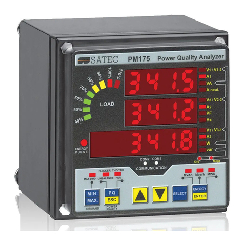
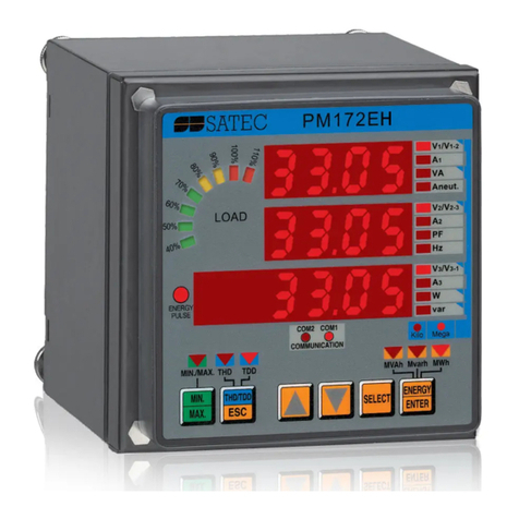
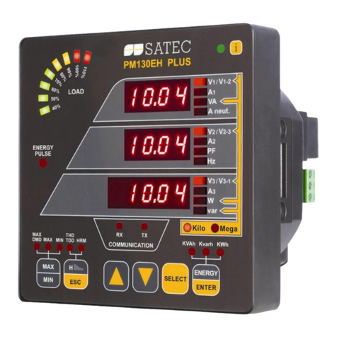
Satec PM130 series User manual

1
PM130 Series Powermeter
PM130 Series Powermeter PM130 Series Powermeter
PM130 Series Powermeter -
--
- Quick Start
Quick Start Quick Start
Quick Start
Typical Mechanical Installation
1.
Figure 1: Mounting the PM130 (Square or Round Cut-out) Figure 2: Physical imensions
Figure 3: CT Wiring
IMPORTANT!
All incoming power sources must be turned off during installation. Setup can be performed by qualified personnel only.
uring operation of the meter, hazardous voltages are present on the input terminals. Failure to observe precautions can result
in serious or even fatal injury, or damage to equipment.
Please refer to the installation and operation manual for further information.
2
NOTE:
Refer to the User
Guide for the wiring
schematics diagrams
Typical Electrical Installation
Figure 4: Common Wiring Mode: 4LL3 or 4L-n3
*
Elementary Setup
All setups can be performed directly from the display panel or via communications using PAS
communication software, except for ommunications and Display setups, which must be performed
directly on the instrument panel.
To set the CT Primary current, perform the following steps:
• Press 3 times: CHG should blink.
• Press 2 times:
• Press ▲ 2 times:
• Press : "5" should blink.
• Use the ▲▼ arrows to scroll to the desired value
(press ▲▼ continuously for quick scrolling).
• Press to save the selected value.
• Press (X3) to return to the display menu.
3OP2
3-wire open delta using 2
CTs
4Ln3∗
∗∗
∗
4-wire Wye using 3 PTs
3dir2
3-wire direct connection
using 2 CTs
4LL3
4-wire Wye using 3 PTs
3OP3
3-wire open delta using 3
CTs
3Ln3
4-wire Wye using 2 PTs
3LL3
4-wire Wye using 2 PTs
SELE T
ENTER
bASc
4Ln3
ConF
menu
option
value
bASc
5
Ct
menu
option
value
SELE T
STA
CHG
OPS
menu
option
value
*connect the ground
PM130 terminals of
the power supply and
of the communication
connectors to the
switchg ear earth
ground, using 1.5
mm
2
/14AWG
dedicated wire.
ENTER
ES
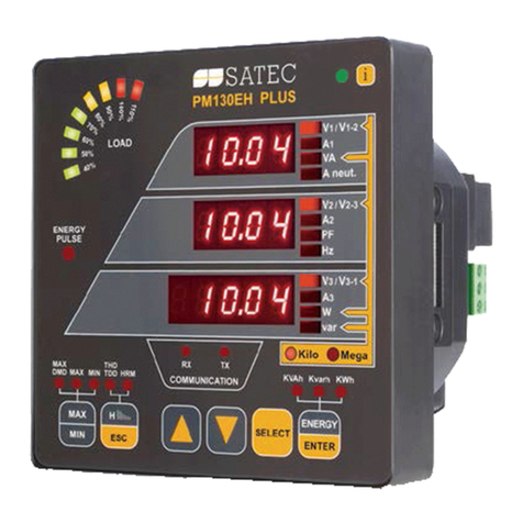
Small LE s indicate
measured parameter
Load bar graph, indicates %
Nominal load current
Round LE s indicate
measurement group
3
Performing Basic and ommunications Setup
• Press (X3) .
• Press ▲▼ to scroll to desired menu.
• Press to activate middle window.
• Press ▲▼ to scroll to desired option.
• Press to activate lower window.
• Press ▲▼ to scroll to desired value.
• Press to save selected value.
• Press (X3) to return to the display menu.
D
DA
AT
TA
A
D
DI
IS
SP
PL
LA
AY
Y
2.
Navigating in Display Mode
The front panel has a simple interface that allows you to display numerous measurement parameters in
up to 38 display pages. For easier reading, the parameters are divided into three groups, each
accessible by a designated key. These are:


 ommon measurements - no selection key


 Min/Max measurements - selected by the key


 Energy measurements - selected by the key
The up/down arrow keys are used as follows in isplay Mode:
Scrolls through the pages downward (forward)
Scrolls through the pages upward (backward)
Returns to the first page within current measurement group
For each display page, up to three parameters can be displayed. The Load bar graph displays the
percentage of the highest of 3 phases current measured by the PM130.
Selecting a Display Page
• Press the ▲▼ to scroll through display pages.
Selecting ommon Measurements
• Press the key pointed to by the illuminated round LE below the front panel display. If no LE is
lit up, the front panel is currently displaying the common measurements parameters.
Selecting Min/Max Measurements
• Press the key. Use the ▲▼ to scroll through Min/Max and Max. demand measurements.
Selecting Energy Measurements
• Press the key. Use the ▲▼ to scroll through the different energy readings.
SELE T
ENTER


ENTER
SELE T
ENTER
bASc
4L/n3
ConF
Port
ASCII
Prot
menu
option
value
menu
option
value
CHG
MAX/MIN
MAX/MIN
ENERGY
ENERGY












ES
4
Basic Menu
ode Parameter Options Description
ConF
Wiring mode 3OP2 3-wire open delta using 2 CTs
4Ln3∗ 4-wire Wye using 3 PTs
3dir2 3-wire direct connection using 2 CTs
4LL3 4-wire Wye using 3 PTs
3OP3 3-wire open delta using 3 CTs
3Ln3 4-wire Wye using 2 PTs
3LL3 4-wire Wye using 2 PTs
Pt
PT ratio 1.0∗ - 6,500.0 The potential transformer ratio
Ct
CT primary current 1-50,000A
(5*)
The primary rating of the current transformer
d P
PM130E
Power demand
period
1, 2, 5, 10, 15*, 20,
30, 60, E
The length of the period for power demand calculations, in minutes
.
E = external synchronization
n dp
PM130E
Number of power
demand periods
1-15
(1*)
The number of demand periods to be averaged for sliding window
demands
1 = block interval demand calculation
A dP
Ampere/Volt
demand period
0-1800
(900*)
The length of the period for volt/ampere demand calculations, in
seconds. 0 = measuring peak current
buF
Averaging buffer
size
8∗,16,32 The number of cycles for RMS sliding averaging
rSt
Reset
enable/disable
diS∗, En Protects all reset functions, both via the front panel or
communications
Freq
Nominal frequency 50, 60 Hz The nominal power utility frequency
ommunication (Port Menu)
ode Parameter Options Description
Prot Communications protocol ASCII
∗
, rtu, dnP3 ASCII, Modbus RTU or NP3.0 protocol
rS Interface standard 485 RS-485 interface (not changeable)
Addr Address ASCII: 0∗-99, Modbus: 1∗-247, NP3.0: 0∗-255
bAud Baud rate 110, 300, 600, 1200, 2400, 4800, 9600*, 19200 bps
dAtA ata format 7E , 8E (7/8 bits, even parity), 8n* (8 bits, no parity)
Input and Output Ratings
IRECT INPUT - Nominal: 690V line-to-line voltage, 790V
maximum; 400V line-to-neutral, 460V maximum - Burden: <0.5
VA. INPUT USING PT - Burden: <0.15 VA
690 V: (standard)
INPUT USING PT - Nominal: 120V line-to-line voltage,
144V maximum - Burden: <0.1 VA
120 V: (optional)
3 voltage inputs
INPUT VIA CT with 5A secondary output - Burden: 2.5 to 4 mm2
(13-11 AWG) wire from CT Overload withstand: 15A RMS
continuous, 250A RMS for 1 second.
5A: (standard)
INPUT VIA CT with 1A secondary output - Burden: 2.5 to 4 mm2
(13-11 AWG) wire from CT Overload withstand: 3A RMS
continuous, 50A RMS for 1 second.
1A:(optional)
3 current inputs
(galvanically
isolated)
Maximum wire section: 4 mm2 (10 AWG) Voltage input terminals
EIA RS-485 standard . Maximum wire section: 2.5 mm2 (12 AWG) Optically isolated communication ports
Relay rated at 3A, 250 V AC / 3A, 30 V C / 0.5A, 110 V C.
Maximum wire section: 1.5 mm2 (14 AWG) 2 contacts (SPST
Form A)
Relay outputs
Maximum wire section: 1.5 mm2 (14 AWG)
88-138V AC or 176-265V AC; 50/60 Hz; Burden: 5 VA
85-265VAC , 88-290V C ; 50/60 Hz 9VA
Power Supply
Galvanically isolated power supply (factory set)
120 or 230 V AC
AC/ C power supply available upon special order
BG0376 Rev. A1

Other manuals for PM130 series

2

Other Satec Measuring Instrument manuals
Satec EM132 User manual

Satec

Satec EM132 User manual

Satec PM135P User manual

Satec

Satec PM135P User manual

Satec PNA295-1 User manual

Satec

Satec PNA295-1 User manual

Satec BFM II EM Specification sheet

Satec

Satec BFM II EM Specification sheet

Satec PM130 PLUS User manual

Satec

Satec PM130 PLUS User manual

Satec PM172P Owner's manual

Satec

Satec PM172P Owner's manual
Satec PM130 series User manual

Satec

Satec PM130 series User manual

Satec expertmeter EM720 User manual

Satec

Satec expertmeter EM720 User manual

Satec PM130 PLUS User manual

Satec

Satec PM130 PLUS User manual

Satec PM130 PLUS Instruction manual

Satec

Satec PM130 PLUS Instruction manual

Satec PM172 Series User manual

Satec

Satec PM172 Series User manual

Satec PM172 Series User manual

Satec

Satec PM172 Series User manual

Satec C191HM User manual

Satec

Satec C191HM User manual

Satec PM175 Series User manual

Satec

Satec PM175 Series User manual

Satec PM171 series User manual

Satec

Satec PM171 series User manual

Satec PM172 Series User manual

Satec

Satec PM172 Series User manual

Satec PM172EH Series User manual

Satec

Satec PM172EH Series User manual

Satec PM290 User manual

Satec

Satec PM290 User manual

Satec expertmeter EM720 User manual

Satec

Satec expertmeter EM720 User manual

Satec System 295 User manual

Satec

Satec System 295 User manual

Satec PM290 User manual

Satec

Satec PM290 User manual

Satec expertmeter EM720 User manual

Satec

Satec expertmeter EM720 User manual

Satec EM133 User manual

Satec

Satec EM133 User manual

Satec Expertmeter Series User manual

Satec

Satec Expertmeter Series User manual

Popular Measuring Instrument manuals by other brands

QuiltCut Strip Savvy Square Up QC2-SU quick start guide

QuiltCut

QuiltCut Strip Savvy Square Up QC2-SU quick start guide

Nedo ACCEPTOR 2 digital operating instructions

Nedo

Nedo ACCEPTOR 2 digital operating instructions

Triplett CM450 user manual

Triplett

Triplett CM450 user manual

Extech Instruments HD300 user guide

Extech Instruments

Extech Instruments HD300 user guide

Extech Instruments 401027 user manual

Extech Instruments

Extech Instruments 401027 user manual

Honeywell VERSAFLOW MAG 200 quick start

Honeywell

Honeywell VERSAFLOW MAG 200 quick start

Ofs Softening Control instruction manual

Ofs

Ofs Softening Control instruction manual

Nivel System CL3D manual

Nivel System

Nivel System CL3D manual

PCE Instruments PCE-EM 890 user manual

PCE Instruments

PCE Instruments PCE-EM 890 user manual

Anritsu MP1900A Series quick start guide

Anritsu

Anritsu MP1900A Series quick start guide

Hanna Instruments HI 98171 instruction manual

Hanna Instruments

Hanna Instruments HI 98171 instruction manual

QED GA5000 operating manual

QED

QED GA5000 operating manual

Matelec KW15110 user manual

Matelec

Matelec KW15110 user manual

PCE Americas PCE-VM 5000 Operation manual

PCE Americas

PCE Americas PCE-VM 5000 Operation manual

Metal Work Pneumatic FLUX Series user manual

Metal Work Pneumatic

Metal Work Pneumatic FLUX Series user manual

CONDTROL NEO G220 user manual

CONDTROL

CONDTROL NEO G220 user manual

CT Lab Vecto III user manual

CT Lab

CT Lab Vecto III user manual

Keysight Technologies PNA-X N5249A Configuration guide

Keysight Technologies

Keysight Technologies PNA-X N5249A Configuration guide

manuals.online logo
manuals.online logoBrands
  • About & Mission
  • Contact us
  • Privacy Policy
  • Terms and Conditions

Copyright 2025 Manuals.Online. All Rights Reserved.