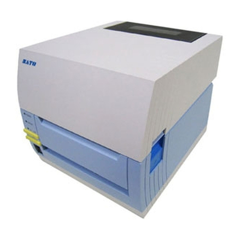
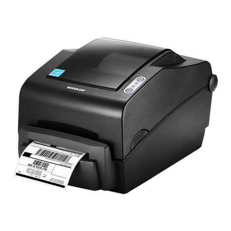
SATO CX Series User manual

CX200
Desktop Label Printer
®
All manuals and user guides at all-guides.com
all-guides.com

1
Rev B
SATO SERVICE MANUAL
CX Series Printers
General Information
1-1 Overview
The SATO CX Series Printers are compact desktop printers designed especially for bar
code labeling and tagging. The CX uses SATO Command Language making it simple
to integrate with any other SATO printer models. Designed for convenience the CX
has many advanced features like larger media capacity user replaceable print head
and platen and a high lift print head carriage that makes it easy to clean and load
supplies.
This manual covers in detail:
CX200DT and CX200TT
Direct Thermal and Thermal Transfer Units
Features include:
••
••
•4.1 inch Wide Print Area
••
••
•Label Width From 2 inches to 4.65 inches
••
••
•Up To 3 inches Per Second Print Speed
••
••
•203 DPI Resolution
••
••
•512K Flash and 512K RAM Memory
••
••
•2Mb or 4Mb Expanded Memory
••
••
•12 Proportional and Mono-spaced Fonts
••
••
•14 Bar Code Symbologies, Including 2D
••
••
•Parallel and Serial Interfaces
Step-by-step maintenance instructions are described in this manual. It is
recommended that you become familiar with each section before installing
and maintaining your printer.
Section
1
All manuals and user guides at all-guides.com

2
Rev B
SATOSERVICE MANUAL
CX Series Printers
1-2 Dimensions
D
H
W
CX200DT CX200TT
Weight 3.1lb./1.41 kg 3.6 lb./1.63 kg
Depth 10 in. (254 mm)
Heigth 6.6 in (168 mm)
Width 6.9 in. (175 mm)
SECTION 1 - GENERAL INFORMATION
All manuals and user guides at all-guides.com

3
Rev B
SATO SERVICE MANUAL
CX Series Printers
1-3 Specifications
Model CX200DT/CX200TT
Print Method Direct Thermal/Thermal Transfer
Resolution 203 dpi 8 dpmm
Max. Media Width 4.65 inches 118 mm
Min Media Width 2.0 inches 51 mm
Max. Print Width 4.1 inches 104 mm
Max. Print Length 14 inches 356 mm
Max. Print Speed 3 ips 76 mm/s
Installed RAM 512 KB, non-volatile
Installed ROM 512 KB, Flash
Communications RS232C Serial and Centronics Parallel
Max. Media Roll OD 5.0 inches 127 mm
Ribbon 460 feet (140m) Wax, Wax/Resin
418 feet (127m) Resin
0.5 inch core, Coated Side Out
Label Sensing method Eye-Mark, Gap or Notch, Fixed Position
Minimum Form Length 0.375 inches 9.5 mm
Text Fonts 12 proportional and monospaced fonts up to 12X expansion
Graphics PCX and SATO Hex/Binary
Bar Codes UPC-A/E, EAN-8/13, UCC/EAN-128, Bookland, Code 39,
I 2 of 5, Code 128, Codabar, Plessey, MSI, Code 93,
Postnet, PDF417, Maxicode
Rotation Text and bar codes can be rotated in four 90oincrements
Power 20-26 VAC 50/60 Hz or 18-26 VDC
120 VAC 50/60 Hz
230 VAC 50/60 Hz
40 W power supply provided with printer
Environmental Operating: 41o to 104oF (5oto 40oC)
Storage: - 4o to 122oF (-20oto 50oC)
RH: 25 to 85% non-condensing
SECTION 1 - GENERAL INFORMATION
All manuals and user guides at all-guides.com

4
Rev B
SATOSERVICE MANUAL
CX Series Printers
1-4 Attributes
READY INDICATOR
ON-LINE/OFF LINE
BUTTON
FEED BUTTON
TOP CASE
PAPER GUIDE
PLATEN ROLLER
REMOVAL ACCESS
SLOTS
WALL
MOUNTING
SLOTS
POWER INPUT POWER CABLE
ROUTING
CHANNEL
SERIAL
PORT
PARALLEL
PORT
EXTERNAL MEDIA
FEED KNOCKOUT
SECTION 1 - GENERAL INFORMATION
BOTTOM CASE
FRONT CASE
All manuals and user guides at all-guides.com

5
Rev B
SATO SERVICE MANUAL
CX Series Printers
1-4 Attributes
RELEASE LEVERS FOR
PRINT HEAD/RIBBON
MECHANISM
PAPER GUIDE (SHOWN
WITH LABELS)
PAPER GUIDE (SHOWN
WITHOUT LABELS)
SECTION 1 - GENERAL INFORMATION
All manuals and user guides at all-guides.com
all-guides.com

6
Rev B
SATOSERVICE MANUAL
CX Series Printers
1-5 Controls, Indicators and Connections
The following table summarizes the functions of the various printer controls
indicators and connections.
PRESS - to advance media
PRESS while pressing READY
indicator-to print test label
PRESS to pause printing during
batch mode operation
GREEN - Printer ready for data
OFF - Printer busy, or Off-Line
RED - Printer needs attention
PRESS to switch to/from Off-Line
or to reset the printer
Connect to power supply pro-
vided with printer
DB9 female connector for connec-
tion to host controller, RS232
interface
Centronics compatible connector
for connection to host controller
Push both releases toward rear of
printer to release print head
Lift to open
Push outward at hinge to remove
FEED button Advances print media
READY indicator Shows print status
ON-OFF line Places printer in On-
Line or Off-Line mode
Power input Connects to power
supply
Serial port Data input
Parallel port Data input
Print head Unlocks print head
release
Media cover Protects print media
mechanism
DEVICE NAME PRIMARY FUNCTION USE
SECTION 1 - GENERAL INFORMATION
All manuals and user guides at all-guides.com

7
Rev B
SATO SERVICE MANUAL
CX Series Printers
1-5 Controls, Indicators and Connections
PIN # DESCRIPTION
2 RXD (printer data input)
3 TXD (printer data output)
5 Ground
7 RTS (printer busy)
8 CTS
1,9 +5 VDC, 200 mA max
PIN # DESCRIPTION
1 Strobe
2-9 Data bits 0-7
10 Acknowledge
11 Busy
12 Out of paper
13 +5 VDC
14-15 No connection
17 Chassis ground
18 +5 VDC
31 Reset
32 Error
16,33 Signal Ground
19-30
34-36 No connection
PARALLEL INPUT
CONNECTOR
CENTRONICS 36 PIN
SERIAL INPUT
CONNECTOR DB9S
1
18
5
1
6
9
1936
BACK END OF
PRINTER
SECTION 1 - GENERAL INFORMATION
All manuals and user guides at all-guides.com

8
Rev B
SATOSERVICE MANUAL
CX Series Printers
POWER INPUT
READY INDICATOR
ON-LINE/OFF LINE
BUTTON
FEED BUTTON
UNDERSIDE OF PRINTER POWER
SUPPLY
AC OUTLET
1. Plug the output of the AC power supply provided with the printer
into the connector on the underside of the printer.
2. Plug the supply into an AC outlet having the correct voltage.
Important!
The required AC voltage is marked on the power supply.
Confirm that your AC voltage matches the power supply
requirements. Do not use any power supply other
then the one provided with the printer.
Note:
CX200 printers consume very little power when idle so are not equipped
with a power switch. Press the READY indicator ON-OFF (a combined
control) to reset the printer and switch from OFF-Line to On-Line mode.
SECTION 1 - GENERAL INFORMATION
1-5 Controls, Indicators and Connections
Printer Power Connection
All manuals and user guides at all-guides.com

9
Rev B
SATO SERVICE MANUAL
CX Series Printers
1-5 Controls, Indicators and Connections
Connecting the Interface Cable
AVAILABLE DB9S
SERIAL PORT PARALLEL PORT
CONNECT THIS END OF THE
CENTRONICS 36 PIN CABLE
TO THE PARALLEL PORT ON
THE PRINTER
CONNECT THIS END OF THE
PARALLEL CABLE TO THE
PORT ON THE COMPUTER
SECTION 1 - GENERAL INFORMATION
All manuals and user guides at all-guides.com

10
Rev B
SATOSERVICE MANUAL
CX Series Printers
ALSO REFER TO THE ACCOMPANYING ILLUSTRATIONS (NEXT PAGE)
1. Lift open the top case.
2. Press the two print head releases toward the rear of the printer to
unlock the print head. The print head will pop up slightly. Lift it up
until it is fully raised.
3. Remove print media (if any) or empty core from the printer.
4. Unwrap the new media and unwind a few labels from the roll. Labels
must be wound face-in for best results.
5. Slide the paper guide all the way to the right.
6. Place media roll in the tray so that the media unwinds from the
bottom of the roll toward the front of the printer. The label imaging
surface must face up as it passes under the print head.
7. Lift the print head and slip the free end of the media under the
print head.
8. Adjust the paper guide until the media is snug between the paper
guide and the left side of the paper tray.
9. Lower the print head and press it down firmly until it locks closed on
both sides.
10. Close the top case.
11. Wait until the Ready Indicator glows green then press the FEED
button to feed a label or to resume printing.
12. If the printer feeds out 7 inches of label and stops and the indicator
glows red recalibrate for the media installed. See calibration.
SECTION 1 - GENERAL INFORMATION
1-6 Printer Setup
Loading Labels or Tags
All manuals and user guides at all-guides.com
all-guides.com

11
Rev B
SATO SERVICE MANUAL
CX Series Printers
PAPER GUIDE
LIFT PRINT HEAD AND
SLIDE UNDER MEDIA
MEDIA ROLL
FEED BUTTON
READY
INDICATOR
SECTION 1 - GENERAL INFORMATION
1-6 Printer Setup
Loading Labels or Tags
PRESS BACK THE
RELEASES TO UNLOCK
All manuals and user guides at all-guides.com

12
Rev B
SATOSERVICE MANUAL
CX Series Printers
ALSO REFER TO THE ACCOMPANYING ILLUSTRATIONS
1. Lift open the top cover.
2. Press the two print head releases toward the rear of the printer to
unlock the printhead. The print head will pop up slightly. Lift it up
until it is fully raised.
3. Unwrap the new ribbon and unwind about 4" from the roll. The end
of the ribbon is attached to a take-up core.
4. Observe the notches on both ends of the supply core and the take-up
core. These notches must fit on the corresponding nibs on both the
supply and take-up spindles.
5. Roll several turns of ribbon on the take-up core winding to the under-
side as shown. The dull (coated) side of the ribbon must be on the
outside of the take-up roll.
6. Place the take-up core (ribbon unrolling from the top side) into the
left take-up spindle lining up the notches with the spindle nibs. The
take-up spindles are the take-up spindles.
7. Pull out the spring loaded knob on the right take-up spindle and place
the right end of the take-up core into the right spindle lining up the
notches with the spindle nibs.
8. Pull the ribbon down and over the print head and insert the supply
core onto the left supply spindle making sure the notches in the core
fit over the nibs.
9. Pull out the spring loaded knob on the right supply spindle and place
the right end of the supply core into the right spindle lining up the
notches with the spindle nibs.
Note:
Make sure the (coated) dull side of the ribbon is to the outside where it will be
in contact with the label media.
The CX200TT Thermal Transfer Printer transfers ink from a ribbon to the label
to produce an image.
Ribbon is N A for CX200DT
SECTION 1 - GENERAL INFORMATION
1-6 Printer Setup
Loading Ribbon
All manuals and user guides at all-guides.com

13
Rev B
SATO SERVICE MANUAL
CX Series Printers
10. Turn the take-up knob to pull the ribbon over the print head without any slack.
Check to make sure there are no ribbon wrinkles.
11. Lower the print head and press it down firmly until it locks closed on both sides.
12. Close the top case.
13. Wait until the Ready Indicator glows green and press the FEED button to feed a
label or to resume printing.
14. If the printer feeds out 7 inches of label and stops and the indicator glows red
recalibrate for the media installed. See calibration.
SECTION 1 - GENERAL INFORMATION
ROLL SEVERAL
TURNS ON THE
TAKE-UP CORE
UNWIND ABOUT 4"
SPINDLE
NOTCHES
BOTH ENDS
SPINDLE
NOTCHES
BOTH ENDS
1-6 Printer Setup
Loading Ribbon (Continued)
DIRECT THERMAL
UNIT SHOWN
(NO RIBBON)
PRESS BACK THE
RELEASES TO UNLOCK
All manuals and user guides at all-guides.com

14
Rev B
SATOSERVICE MANUAL
CX Series Printers
PLACE TAKE-UP
CORE INTO LEFT
TAKE-UP SPINDLE
SECTION 1 - GENERAL INFORMATION
SPRING LOADED
RIBBON TAKE-UP
KNOB
SUPPLY ROLL
PRINT HEAD
PULL THE RIBBON OVER
THE PRINT HEAD
1-6 Printer Setup
Loading Ribbon (Continued)
TAKE-UP
CORE
SUPPLY
KNOB
TAKE-UP KNOB
All manuals and user guides at all-guides.com

15
Rev B
SATO SERVICE MANUAL
CX Series Printers
SECTION 1 - GENERAL INFORMATION
LOWER THE PRINT HEAD
AND PRESS DOWN FIRMLY
ON BOTH HEAD LATCHES
TO LOCK THE PRINT HEAD
IN POSITION
1-6 Printer Setup
Loading Ribbon (Continued)
TURN RIBBON TAKE-UP
KNOB CLOCKWISE TO
ELIMINATE RIBBON
SLACK
Selecting the Label Sensor Type
CX200 printers support Eye-Mark gap or notch label sensing. The printer must be
set for the proper sensing method. If you are using label printing software it should
provide a means to set up these parameters. See your software documentation for
details. If you are writing your own software or controlling the printer using direct
commands you must use printer commands to set up the print mode and sensing
method. Refer to the programming manual.
All manuals and user guides at all-guides.com
all-guides.com

16
Rev B
SATOSERVICE MANUAL
CX Series Printers
1-7 Printer Test and Calibration
Preparation for Test
Cuts or gouges in the rubber drive roller
Dust buildup or other obstructions of the label sensor or sensor LED
Adhesive buildup or scratches on the print head
Adhesive buildup or other obstructions in the paper path
Any other physical damage that might affect printer alignment
These procedures run a complete set of performance tests. If the printer fails a test
troubleshoot as required then rerun all tests.
Inspect the printer for physical damage before testing or calibrating it. Inspect for:
Correct any problems found before beginning the printer calibration using the
calibration software.
NOTE:
The calibration software is DOS-based and can be run directly
from the diskette or installed on your hard drive. You must run
the software from the DOS prompt. If using Windows 95, reboot
your computer in MS-DOS mode. Do not try to run the software
in a window.
Installing the software to your hard drive:
1. At the DOS prompt insert the calibration disk in your computer's 3-1/2 disk
drive and access the drive.
2. At the prompt type dir and press the Enter key.
3. Copy the file CX200.exe to your hard drive.
4. Type CX200.exe to view the opening screen. Refer to the following pages
to continue with the program.
All manuals and user guides at all-guides.com

17
Rev B
SATO SERVICE MANUAL
CX Series Printers
1-7 Printer Test and Calibration
Preparation for Test
Running the software from your 3-1 2 drive
1. At the DOS prompt insert the calibration disk in your computer's 3-1/2 disk
drive and access the drive.
2. At the prompt type CX200.exe and press the Enter key. The opening
screen will appear.
Review the menu and make your selection. At the prompt type 1 2 3 4
or to exit the program type 0.
Description of Test Menu
1. Print Head / Status Print - Prints head pattern status. Refer to illustra-
tion on page 26
2. Change RS232 Settings - Sets the RS232 settings through the LPT1 port
3. Set Top of Form - Positions the label towards or away from the sensor.
4. Calibrate Printer - Calibrates printer to current label and/or ribbon
installed in the machine.
All manuals and user guides at all-guides.com

18
Rev B
SATOSERVICE MANUAL
CX Series Printers
1-7 Printer Test and Calibration
Print Head / Status Print
1
Access the software
1. Enter 1 at the prompt.
2. As the sequential screens appear respond to the prompts.
Refer to page 26 for an example of a test label.
All manuals and user guides at all-guides.com

19
Rev B
SATO SERVICE MANUAL
CX Series Printers
Access the software
1. Enter 2 at the prompt.
1-7 Printer Test and Calibration
Change RS232 Settings
2. As the sequential screens appear respond to the prompts.
2
All manuals and user guides at all-guides.com
Other manuals for CX Series
2
This manual suits for next models
1
Table of contents
Other SATO Label Maker manuals
SATO
SATO TG3 Series User manual

SATO
SATO SX4M User manual
SATO
SATO s84ex User manual
SATO
SATO CLLM Basic 412e User manual
SATO
SATO GZ4e Series User manual
SATO
SATO CL4NX RIDF User manual
SATO
SATO LM400e Series User manual

SATO
SATO SG112-ex User manual

SATO
SATO CL4NX RIDF User manual
SATO
SATO Argox D4 Series User manual

