SATO S8412 Standard User manual

PN: 9001160B
S8408/S8412/S8424
PRINTERS
OPERATOR MANUAL

PN: 9001160B
SATO America, Inc.
10350A Nations Ford Road
Charlotte, NC 28273
Main Phone: (704) 644.1650
Technical Support Hotline: (704) 644.1660
Technical Support Fax: (704) 644.1661
E-Mail: satosale[email protected]
techsupport@satoamerica.com
www.satoamerica.com
WARNING
THE EQUIPMENT REFERENCED IN THIS DOCUMENT COMPLIES WITH THE REQUIREMENTS IN PART 15
OF FCC RULES FOR A CLASS B COMPUTING DEVICE. OPERATION OF THIS EQUIPMENT IN A
RESIDENTIAL AREA MAY CAUSE UNACCEPTABLE INTERFERENCE TO RADIO AND TV RECEPTION.

S8400 Series Operator Manual PN: 9001160B
TABLE OF CONTENTS
INTRODUCTION
About This Manual 1-2
General Description 1-3
Control Features 1-5
TECHNICAL DATA
Physical Characteristics 2-2
Power 2-2
Enviromental 2-2
Processing 2-2
Command 2-2
Interface Modules 2-2
Regulatory Approvals 2-2
Print 2-3
Media 2-3
Ribbon 2-3
Sensing 2-4
Character Font Capabilities 2-4
Barcode Capabilities 2-5
INSTALLATION
Unpacking & Parts Identification 3-2
Printer Installation 3-3
Printer Loading 3-5
Operational Mode Selection 3-8
Interface Selection 3-9
RS232C High-Speed Serial Interface 3-10
IEEE1284 Parallel Interface 3-12
Universal Serial BUS (USB) Adapter 3-13
Local Area Network (LAN) Ethernet 3-14
802.11G Wireless 3-15
All Interfaces 3-17
Accessories Installation 3-25
Interface 3-25
Remote Operator Panel 3-26

S8400 Series Operator Manual PN: 9001160B
PRINTER CONFIGURATION
Printer Configuration 4-2
Configuration Modes 4-3
User Mode 4-3
Advanced Mode 4-4
Parallel Interface Mode 4-5
Serial Interface Mode 4-6
Local Area Network (LAN) Interface Mode 4-7
Universal Serial BUS (USB) Interface Mode 4-8
Centronics Interface Mode 4-9
Wireless LAN (Local Area Network) Interface Mode 4-10
Service Mode 4-11
Factory Mode 4-12
Work Shift Mode 4-13
Hidden Mode 4-14
Download Mode 4-15
Boot Download Mode 4-16
Print Cancel Mode 4-17
Default Settings Mode 4-18
Test Print Mode 4-19
Hex Dump Mode 4-20
CF (Compact Flash) Card Mode 4-21
Stand Alone Mode 4-22
Menu Definition Tables 4-23
TROUBLESHOOTING
Error Signal Troubleshooting 5-2
Warning Signal Troubleshooting 5-6
Troubleshooting Table 5-7
Interface Troubleshooting 5-9
Parallel Interface 5-9
RS232 Serial Interface 5-9
Universal Serial Bus (USB) Interface 5-9
LAN Ethernet Interface 5-10
802.11g Interface 5-10
Centronics Interface 5-10
Test Print Troubleshooting 5-11
Hex Dump Mode 5-11
Test Label Printing 5-11
Sample Test Label 5-11

S8400 Series Operator Manual PN: 9001160B
MAINTENANCE
Cleaning Procedures 6-2
Replacement Procedures 6-3
Print Head 6-3
Platen Rollers 6-4
Interface Board 6-5
Fan Filter 6-6
Adjustment Procedures 6-7
Label Sensor Positioning 6-7
Print Head Pressure 6-8
Print Head Alignmnent 6-9
Ribbon Guide Alignment 6-10
Media Pressure Roller Balance 6-11
Ribbon Cassette Belt Tensioning 6-12
Print Head Balance 6-13
Eye-Mark/Paper-End Sensor Sensitivity 6-14
Gap Sensor Sensitivity 6-15
Operational Adjustments 6-16
Pitch 6-16
Offset 6-16
Darkness 6-16
APPENDIX
Ready/Busy timing Charts 7-2
X-On/X-Off Timing Charts 7-3
Session Connect/Disconnect Diagram 7-4
Printer Dimensions (Standard w/Cassette) 7-5
Printer Dimensions (Opposite w/Cassette) 7-8
Printer Dimensions (Standard Direct Load) 7-11
Printer Dimensions (Opposite Direct Load) 7-14
Glossary 7-17

S8400 Series Operator Manual 1-1 PN: 9001160B
INTRODUCTION
• About This Manual
• General Description
• Control Features

Unit 1: Introduction
S8400 Series Operator Manual 1-2 PN: 9001160B
ABOUT THIS MANUAL
This manual is laid out consistent with the product discussed and provides all of the information required for
general printer configuration, operation, troubleshooting, and maintenance. For specialized programming, refer to
the Programming Reference document.
Step-by step maintenance instructions are provided with typical problems and solutions. Become familiar with each
unit and section before installing and maintaining the printer.
This manual also incorporates the use of special information boxes. Examples of these boxes and the type of
information provided in each, are below.
A comprehensive Table Of Contents provided at the front of this manual facilitates rapid movement within. The
contents identify the different Units, Chapters, and some Sections. Each references the page number of their
commencement.
The pages of this manual have embedded headers and footers to assist the user in identifying his or her exact
position within the manual. The header provides the unit number followed by its name. The footer identifies the
product on the left, the page number in the center, and the manual’s part number to the right side of the page.
Page enumeration is two-part with each separated by a hyphen. The first character set references the Unit and the
second identifies the page number within that unit. Page numbers begin with the numeral one (1) at the beginning
of a new unit and ascend sequentially.
WARNING: PROVIDES INFORMATION THAT, IF UNHEEDED, MAY RESULT IN
PERSONAL INJURY.
CAUTION: PROVIDES INFORMATION THAT, IF UNHEEDED, MAY RESULT IN
EQUIPMENT DAMAGE.
ATTENTION: Provides information that is deemed of special importance but will not
result in personal injury or product damage if unheeded.
NOTE: Provides helpful hints to assist in performing the tasks at hand.
LCD DISPLAY: Provides the specific display that should be visible on the LCD at that
point.
ATTENTION: The illustrations and graphics provided in this manual may display
components, assemblies, and purchase options that may not be present on idividual
printers. However, where those instances arise, they are not revalent to the topic
discussed.
Unit 1: Introduction
S8400 Series Operator Manual 1-3 PN: 9001160B
GENERAL DESCRIPTION
The S8400 series print engines are specifically designed for use in high-volume, automated print/apply labeling
applications demanding unparalleled reliability and around the clock operation. These print engines offer four-inch
wide printing ability and are available in 203, 305, and 609 dpi print resolution. However, more compelling is their
user-friendly design and application flexability.
These OEM print engines follow the design concepts and principles of SATO’s previous, market leading, industrial
print engines. The S8400 series can physically and electronically replace any of SATO’s previous S-type OEM
print engines. Additionally, this printer utilizes the same SATO Barcode Printing Language (SBPL) as drives all
current SATO OEM print engines.
The S8400 series print engine is available with many options, including quick-change ribbon cassette, ribbon
saver, and RFID capability.
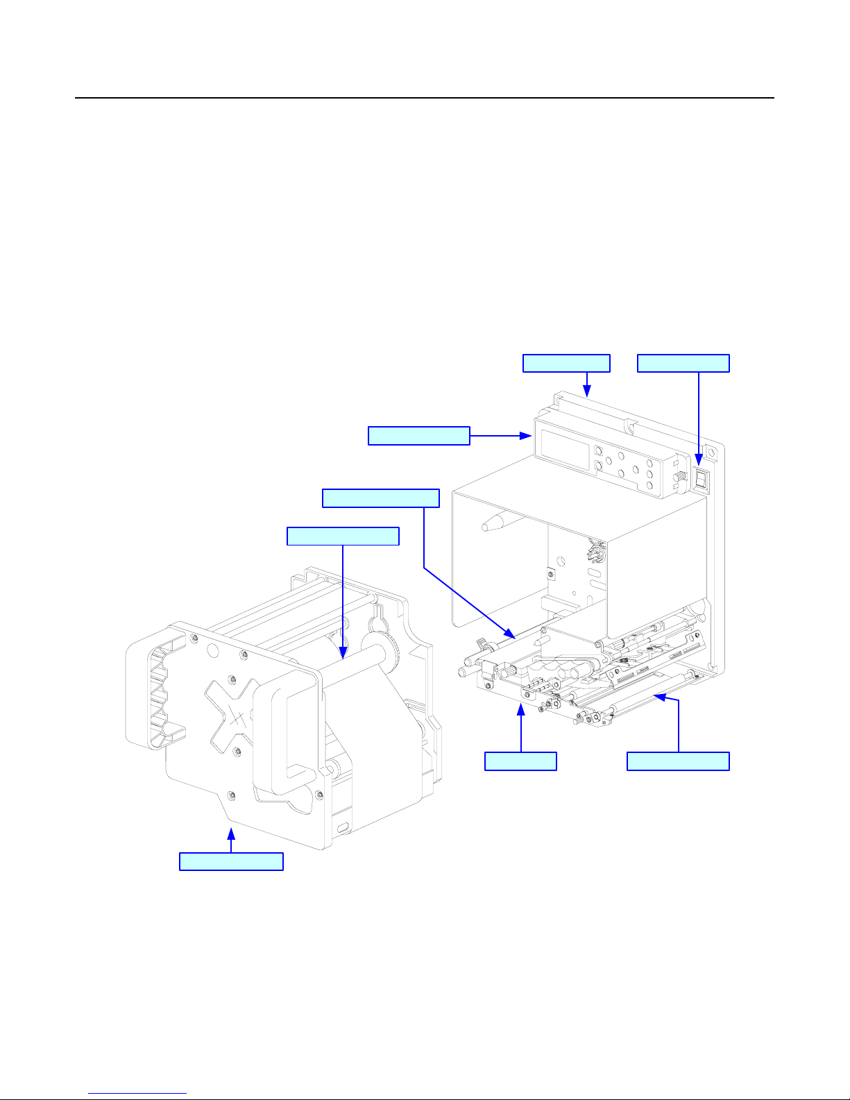
Figure 1-1a, Primary Components
Platen Roller x3
Ribbon Cassette
Chassis
Ribbon Spindle x2
Center Frame
Operator Panel
Label Sensor Assy
Power Switch

Unit 1: Introduction
S8400 Series Operator Manual 1-4 PN: 9001160B
Figure 1-1b, Primary Components
Ribbon Roller x2
Print Head Latch
Ribbon Supply Spindle
Front Housing Cover
Label Sensor Adjustment Knob
Rear Housing Covers
Ribbon Rewind Spindle
Media Guide
Ribbon Guide
Head Pressure Knob
Head Balance
Printer Chassis

Unit 1: Introduction
S8400 Series Operator Manual 1-5 PN: 9001160B
CONTROL FEATURES
This chapter identifies the interactive control features of the printer. These functions are defined generally here.
More specific explanations will be found throughout this manual on how to use them.
Figure 1-2, Operator Panel
OPERATOR PANEL FEATURES
LED DEFINITION
POWER Illuminates green when the printer is powered on. Terminates when powered off.
ONLINE Illuminates green when the printer is in an online state. Terminates when the printer goes offline.
LABEL Off = Normal state.
Red Constant = When a Label Error has occurred.
RIBBON Off = Normal state.
Red Flashing = Ribbon supply is low.
Red Constant = When a Ribbon Error has occurred.
KEYS DEFINITION
POWER Removes power supply at its entry to the printer.
LINE Moves the printer from an online to offline state and vise-versa. Has other special functions as
identified in flow charts throughout this manual as applicable.
FEED Advances the label media when pressed. Has other special functions as identified in flow charts
throughout this manual as applicable.
FUNCTION Pressing steps the LCD back to a previous menu. Has other special functions as identified in flow
charts throughout this manual as applicable.
ENTER Used to select a menu option and to advance the menu screen accordingly. Has other special
functions as identified in flow charts throughout this manual as applicable.
CANCEL Pressing steps the LCD back to a previous menu. Has other special functions as identified in flow
charts throughout this manual as applicable.
ARROWS Allows the operator to scroll through various menus and menu options. Has other special
functions as identified in flow charts throughout this manual as applicable.
POTENTIOMETERS DEFINITION
VOLUME Allows volume control of the printer’s audible alarm.
PITCH For adjusting the print position.
OFFSET Adjusts the peel or dispense stop position.
DARKNESS Adjusts the print density resulting in a lighter or darker print image.
ENTER
CANCEL
FUNCTION
LINE
FEED
LCD DISPLAY

S8400 Series Operator Manual 2-1 PN: 9001160B
TECHNICAL DATA
• Physical Characteristics
•Power
• Environmental
• Processing
• Command
• Interface Modules
• Regulatory Approvals
•Print
•Media
• Ribbon
• Sensing
• Character Font Capabilities
• Barcode Capabilities

Unit 2: Technical Data
S8400 Series Operator Manual 2-2 PN: 9001160B
PHYSICAL CHARACTERISTICS
Typical Width 9.65 Inches (245mm)
Typical Height 11.81 Inches (300mm)
Maximum Depth 18.82 Inches (478mm)
Standard Weight 35.27 Pounds (16.0Kg)
POWER
Input Voltage 100-240 Volts AC +/- 10%, 50/60 Hertz +/-5%
Power Consumption 220 Watts, 2.7 to 1.1 Amperes (operating)
Accelleration Perfomance 3.5G (Frequency: 10Hz or below, Vibration Time: within 5 minutes)
ENVIRONMENTAL
Operating Temperature 41 to 104°F (5° to 40°C)
Storage Temperature 0 to 140°F (-20° to 60°C)
Storage Humidity 15 to 85% RH Non-Condensing
Operating Humidity 15 to 85% RH Non-Condensing
PROCESSING
CPU 32 Bit RISC
FLash ROM 4 Megabytes
SDRAM 16 Megabytes
FRAM 32 Kilobytes
Receive Buffer 2.95 Megabytes
SRAM (integrated calendar) 8 Kilobytes
COMMAND
Standard SATO Barcode Printer Language (SBPL)
INTERFACE MODULES
Enhanced Parallel Port IEEE1284 (ECP Compatible)
Serial Port
RS232C (9600 to 57,600 bps) - 25 Pin
RS422/485 (9600 to 57600 bps)
RS232C - 9 Pin PCI
Universal Serial Bus (USB) USB Adapter (12 Mbps) - PCI
Local Area Network (LAN) 10BASE-T/100BASE-TX Automatic Switching
Wireless LAN 802.11g Wireless
REGULATORY
Safety MET, NEMKO-GS, C-MET
Radiant Noise FCC (Class B), EN 55022 (Class B)
Efficiency International Energy Star
Packaging Drop Test ISTA-2A

Unit 2: Technical Data
S8400 Series Operator Manual 2-3 PN: 9001160B
PRINT
Method Direct Thermal / Thermal Transfer
Head Width 4.09 Inches (104mm)
Maximum Speed
203 Dots Per Inch (8dpmm): 4 to 16 Inches Per Second (102-406mm/s)
305 Dots Per Inch (12dpmm): 4 to 14 Inches Per Second (102-356mm/s)
609 Dots Per Inch (24dpmm): 2 to 6 Inches Per Second (51-152mm/s)
Resolution
203 Dots Per Inch (8dpmm)
305 Dots Per Inch (12dpmm)
609 Dots Per Inch (24dpmm)
Maximum Printable Area
203 Dots Per Inch (8dpmm): 4.09 x 98.4 Inches Wide (104mm W x 2500mm L)
305 Dots Pre Inch (12dpmm): 4.09 x 59.0 Inches Wide (104mm W x 1500mm L)
609 Dots Per Inch (24dpmm): 4.09 x 15.7 Inches Wide (104mm W x 400mm L)
MEDIA
Width Media Width: 0.394 to 5.039 Inches (10-128 mm)
Media Width with Backing Paper: 0.5 to 5.1 Inches (13-131 mm)
Length (Pitch) Media Length: 0.6 Inches (15 mm) (to printable area)
Type Die-Cut Labels, Waste removed, Roll, 0.125 inch Gap or Eye-Mark
Thickness 0.002 to 0.012 Inches (0.05 - 0.31mm)
Media Handling
Media Width (mm) Label Supply Load (grams) Liner Rewind Load (grams)
13 to 18 < 250 < 150
18 to 28 < 400 < 300
28 to 48 < 900 < 300
48 to 63 < 1,200 < 400
63 to 83 < 1,200 < 650
83 + < 1,400 < 800
RIBBON
Width Minimum: 0.98 Inches (25mm)
Maximum: 5.04 Inches (128mm)
Length 3280 Feet (1000m)
Ribbon Handling
Ribbon Length (m) Ribbon Width (mm) Label Pitch (mm)
1,000 76 60 +
600 39.5 to 75 25 +
450 < 39.5 < 25
Wound Face In / Face Out
Roll Diameter 4.252 Inches (108mm)
Core Diameter 1.01 +/-0.008 Inches (25.6mm +/-0.2mm)
Color Black (standard), Other Tints (non-standard)

Unit 2: Technical Data
S8400 Series Operator Manual 2-4 PN: 9001160B
SENSING
Gap Adjustable
Reflective Eye-Mark Adjustable
Ribbon Near End Enable/Disable
Media Out Constant
Cover-Open Constant
Head-Open Constant
CHARACTER FONT CAPABILITIES
MATRIX FONTS
XU 5 dots W x 9 dots H (Helvetica)
XS 17 dots W x 17 dots H (Univers Condensed Bold)
XM 24 dots W x 24 dots H (Univers Condensed Bold)
OA Font (OCR-A)
203dpi (8dots/mm): 15 dots W x 22 dots H
305dpi (12dots/mm): 22 dots W x 33 dots H
609dpi (24dots/mm): 44 dots W x 66 dots H
OB Font (OCR-B)
203dpi (8dots/mm): 20 dots W x 24 dots H
305dpi (12dots/mm): 30 dots W x 36 dots H
609dpi (24dots/mm): 60 dots W x 72 dots H
AUTO SMOOTHING FONTS
XB 48 dots W x 48 dots H (Univers Condensed Bold)
XL 48 dots W x 48 dots H (Sans Serif)
VECTOR FONT
Proportional or Fixed Spacing
Font Size 50 x 50 dots to 999 x 999 dots
Helvetica, 10 Font Variations
AGFA RASTER FONTS
A Font CG Times, 2 to 99 pt. (4-999 dots)
B Font CG Triumvirate, 2 to 99 pt. (4-999 dots)
DOWNLOADABLE FONTS
Compact Flash Card required
CHARACTER CONTROL
Expansion up to 12 x in either the X or Y coordinates.
Character Pitch Control
Line Space Control
Journal Print Facility
0, 90, 180, and 270 Degree Rotation
Unit 2: Technical Data
S8400 Series Operator Manual 2-5 PN: 9001160B
BAR CODE CAPABILTIES
Linear Bar Codes
UPC A/E
EAN 8/13
Code 39
Code 93
Code 128
Interleaved 2 of 5
Industrial 2 of 5
Matrix 2 of 5
Bookland
RSS-14
MSI
POSTNET
UCC/EAN 128
NW-7 (Codabar)
Two Dimemsional
QR Code
Data Matrix (ECC200)
Maxi Code
PDF417
Composite Symbology
Bar Width Ratio 1:2, 1:3, 2:5, User definable bar widths
Bar Height 4 to 999 dots, User progammable
Rotation 0, 90, 180, and 270 Degrees
Sequential Numbering Sequential numbering of both numerics and bar codes
Graphics Full dot addressable graphics, SATO Hex/Binary, BMP or PCX formats
Form Overlay Form overlay for high-speed editing of complex formats

S8400 Series Operator Manual 3-1 PN: 9001160B
INSTALLATION
• Unpacking & Parts Identification
• Printer Installation
• Printer Loading
• Operational Mode Selection
• Interface Selection
• Accessories Installation

Unit 3: Installation
S8400 Series Operator Manual 3-2 PN: 9001160B
UNPACKING & PARTS IDENTIFICATION
Unpack the printer as directed in the folowing procedure.
1. Place the shipping container (box) upright on a stable, flat surface.
2. Open the box, remove any loose items and the first layer of packing material.
3. Carefully lift the printer and accessories from the box and place them on a stable, flat surface.
4. Remove the plastic covers from the packed items and visually inspect for physical damage.
5. Ensure all components are present as dictated on the Packing List.
6. Report damaged property to the shipping carrier.
Figure 3-1, Unpacking

Unit 3: Installation
S8400 Series Operator Manual 3-3 PN: 9001160B
PRINTER INSTALLATION
This chapter provides guidance on how to station, connect, and load the printer once unpacked. Following printer
setup, proceded to the next chapter for information on interface selection.
SITE LOCATION
• Stationed away from hazardous materials.
• Stationed within an enclosed structure that conforms to the printer’s enviromental requirements.
• Stationed within operational distance of the host based on interface specifications.
• Stationed to allow unimpeded access to the printer for operation, loading, and maintenance.
INSTALLATION REQUIREMENTS
The printer has five bores in its center frame for the purpose of mounting to a support structure. Refer to the
following list of mounting requirements.
• The support structure must be firmly secured to the floor or production machinery.
• The support structure must be sturdy and stable so as to prevent unnecessary movement or vibration.
• The printer is to be mounted to the support structure using attaching hardware design to accommodate the
printer’s weight, as well as, the prevailing operational and enviromental conditions within the facility.
• A power supply recepticle or junction box is to be properly secured within regulated proximity to the printer.
• The power supply is to be metered condusive to the printer’s design requirements.
• The printer must be installed so that its output side is within the designated distance and height relative to the
applicator.
• Media supply dispensers must be mounted or placed with operational distance of the printer’s input side.
Figure 3-2, Typical Printer/Applicator Process
NOTE: Figures 3-2 and 3-3 are to be used as instructional displays only and are not to
be literally interpretted as precise examples.
Applicator
Printer
Packaging
Production Line

Unit 3: Installation
S8400 Series Operator Manual 3-4 PN: 9001160B
Figure 3-3, Printer Mounting
Figure 3-4, Printer Connection
ATTENTION: Figure 3-4 displays the printer interfaced with a host computer.
However, the printer may also be interfaced with a PLC, keyboard, scanner, etc.
OR
Applicator
Host Computer
Breaker Box
Interface Card
Power Cord
Printer
EXT Interface
Interface Cable

Unit 3: Installation
S8400 Series Operator Manual 3-5 PN: 9001160B
PRINTER LOADING
MEDIA SELECTION
The size and type of labels to be printed should have been taken into consideration before printer purchase.
Ideally, the media width will be equal to, or just narrower than, the print head. Using media that does not cover the
print head will allow the platen roller to tread upon its surface resulting in premature wear. The media edge will also
wear a groove in the platen roller affecting print quality.
There are two types of media that may be used: thermal transfer and direct thermal. Thermal transfer media
requires the use of ribbon stock for print application. In such a scenario, it is the ribbon stock (carbon paper) that
contains the ink that will be transfered to the media.
Direct thermal media has thermally reactive material embedded within and is brought to the surface through heat
penetration by print head contact. Only load ribbon stock into the printer if that media type is to be used.
MEDIA LOADING
To load label media, unlatch the print head and remove any remnants that may exist of the prior media supply.
Feed the free end of the media from the printer’s left side, beneath the shaft of the media guide, between the upper
and lower halves of the label sensor, across the top of all forthcoming rollers, and through to protrude six or more
inches beyond the printer chassis.
Ensure the media is flush against the printer’s back side (toward the center wall) and then adjust the media guide
inward until it almost makes contact with the media’s backing paper.
Remove all labels from the backing paper that extend beyond the printer chassis and relatch the print head.
Lift upward on the pressure roller release knob (purple) and allow the pressure roller plate to fall to a vertical
position. Route the backing paper’s free end around the front of the printer chassis, beneath the front platen roller
and onward between the second platen roller and the pressure roller. Pull the free end of the backing paper to
remove all slack while lifting the pressure plate until latched. Refer to Figures 3-5 and 3-6 for visual assistance.
RIBBON LOADING
To load ribbon stock, unlatch the print head and remove exhausted ribbon stock if applicable. Insert an unused
ribbon roll, with ribbon core, fully onto the ribbon supply boss (left) and an empty core onto the ribbon rewind boss
(right). Route the ribbon’s free end around the print assembly and tape it to the blank core on the rewind boss.
Rotate the core a couple of times while holding the boss stationary to take up take up slack. Refer to Figure 3-5 and
Figure 3-6 for visual assistance.
WARNING: AVOID PHYSICAL CONTACT WITH THE PRINT HEAD TO PREVENT
BURNED FINGERS/HANDS AND COMPONENT DAMAGE.
NOTE: Properly installed label media will be oriented so that the label side is upward
and the backing paper is downward resting upon the printer chassis.
NOTE: Refer to the Printer Configuration unit of this manual for media configuration
instructions and the Adjustment chapter of the Maintenance unit for label sensor
adjustment instructions as necessary.
NOTE: Properly installed ribbon stock will be oriented so that its dull, ink side is facing
the printer chassis while the ribbon is dispensed and taken up on the right side of
each roll. The non-ink side of the riibon stock is the shiniest of the two surfaces.
This manual suits for next models
2
Table of contents
Other SATO Printer manuals

SATO
SATO CL408e User manual

SATO
SATO CL608VA Use and care manual

SATO
SATO CX200 User manual

SATO
SATO s84ex Owner's manual

SATO
SATO M-8400RVe Series Use and care manual

SATO
SATO WS408TT User manual

SATO
SATO M-8450 User manual

SATO
SATO CG408TT User manual

SATO
SATO MB 200i User manual

SATO
SATO XL400 User manual


