SATO S84 ex User manual

Service Manual
For printer model:

Copyrights
Any unauthorized reproduction of the contents of this document, in part or whole, is strictly prohibited.
Limitation of Liability
SATO Corporation and its subsidiaries in Japan, the U.S. and other countries make no representations or
warranties of any kind regarding this material, including, but not limited to, implied warranties of
merchantability and fitness for a particular purpose. SATO Corporation shall not be held responsible for errors
contained herein or any omissions from this material or for any damages, whether direct, indirect, incidental or
consequential, in connection with the furnishing, distribution, performance or use of this material.
Specifications and contents in this document are subject to change without notice.
Trademarks
SATO is a registered trademark of SATO Holdings Corporation and its subsidiaries in Japan, the U.S. and
other countries.
Secure Digital (SD) Card is a registered trademark of the SD Card Association.
QR Code is a registered trademark of DENSO WAVE INCORPORATED.
Bluetooth is a trademark of Bluetooth SIG, Inc., U.S.A.
All other trademarks are the property of their respective owners.
Version: GBS-S84ex_S86ex-r02-07-11-14SM
© 2015 SATO Corporation. All rights reserved.

1
S84-ex/S86-ex Service Manual
Table of Contents ................................................................................... 1
1 Introduction .......................................................................................... 5
1.1 About This Manual.............................................................................................. 5
1.2 Safety Precautions.............................................................................................. 5
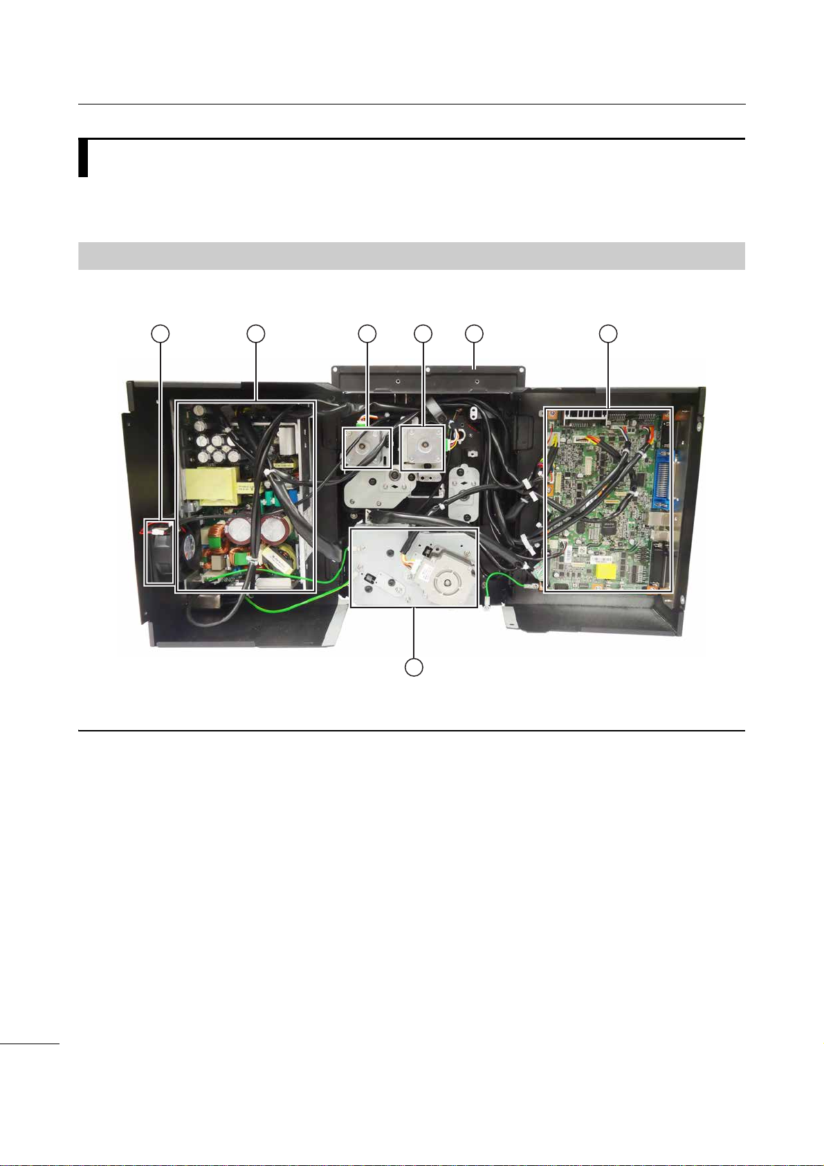
1.3 Parts Identification of the Printer ...................................................................... 6
1.3.1 Internal View with Rear Cover Opened..................................................................... 6
2 Operation and Configuration................................................................ 7
2.1 Operating Modes................................................................................................. 7
2.1.1 History Data Save Mode............................................................................................ 8
2.1.2 KB Download Mode................................................................................................. 14
2.1.3 Default Head Mode (Changing Head Density)........................................................ 16
2.1.4 RFID Mode .............................................................................................................. 17
2.2 List of Initial Values .......................................................................................... 19
2.2.1 Normal Mode........................................................................................................... 19
2.2.2 User Mode............................................................................................................... 19
2.2.3 Interface Mode......................................................................................................... 20
2.2.4 Memory Mode.......................................................................................................... 23
2.2.5 Advanced Mode....................................................................................................... 23
2.2.6 Service Mode........................................................................................................... 26
2.2.7 RFID Mode .............................................................................................................. 27
2.2.8 RFID User Mode...................................................................................................... 28
2.2.9 Hidden Setting Mode............................................................................................... 29
2.2.10 Work Shift Setting Mode........................................................................................ 29
3 Troubleshooting.................................................................................. 31
3.1 Troubleshooting Flowchart.............................................................................. 31
3.1.1 Power Problem........................................................................................................ 31
3.1.2 Feed Problem.......................................................................................................... 32
3.1.3 Print Problem........................................................................................................... 35
3.1.4 Media Problem ........................................................................................................ 40
4 Checking and Performing Printer Adjustments................................. 41
4.1 Functional Structure of Main (CONT) PCB ..................................................... 42
4.2 Checking the Direct Current Power Voltage................................................... 44
4.3 Test Print Check................................................................................................ 46
4.4 Adjusting the Print Position............................................................................. 47
4.5 Checking the Ribbon End Function ................................................................ 48
Table of Contents

Table of Contents
2S84-ex/S86-ex Service Manual
4.6 Checking the Head Open Error........................................................................ 50
4.7 Checking the Top Cover Open Error............................................................... 51
4.8 Adjusting the Timing Belt Tension
(Gearbox) ........................................................................................................... 52
4.9 Adjusting the Timing Belt Tension (Ribbon Motors, Optional Ribbon Saver
Motor)................................................................................................................. 53
5 Replacement....................................................................................... 55
5.1 Removing the Housing Cover.......................................................................... 56
5.1.1 Opening the Rear Housing Cover ........................................................................... 56
5.1.2 Removing the Front Housing Cover........................................................................ 57
5.2 Replacing the Print Head.................................................................................. 59
5.2.1 Replacing the Print Head (without the Optional UHF RFID Antenna Installed)....... 59
5.2.2 Replacing the Print Head (with the Optional UHF RFID Antenna Installed)............ 61
5.3 Replacing the Platen Roller, Pressure Roller and Feed Roller..................... 64
5.3.1 Replacing the Platen Roller..................................................................................... 64
5.3.2 Replacing the Pressure Roller................................................................................. 66
5.3.3 Replacing the Media Feed Roller............................................................................ 68
5.4 Replacing the Media Sensor ............................................................................ 70
5.5 Replacing the Main (CONT) PCB ..................................................................... 73
5.6 Replacing the Operator Panel KB PCB........................................................... 75
5.7 Replacing the Power Supply Unit.................................................................... 76
5.8 Replacing the Fan Motor .................................................................................. 77
5.9 Replacing the Timing Belt................................................................................ 78
5.9.1 Replacing the Timing Belt of Gearbox..................................................................... 78
5.9.2 Replacing the Timing Belt of Ribbon Motors ........................................................... 80
5.9.3 Replacing the Timing Belt of Ribbon Unwind Mechanism....................................... 82
5.10 Replacing the Ribbon Sensor........................................................................ 85
5.11 Replacing the Ribbon End Sensor ................................................................ 87
5.12 Replacing the Head Open Sensor ................................................................. 90
5.13 Replacing the Media Sensor Assembly Open Sensor................................. 91
5.14 Replacing the Top Cover Sensor................................................................... 92
5.15 Replacing the USB PCB ................................................................................. 93
5.16 Replacing the Torque Limiter for Ribbon Spindle ....................................... 94
5.17 Replacing the Torque Limiter for Ribbon Roller.......................................... 96
5.18 Replacing the Optional Ribbon Saver Motor Driver PCB............................ 99

Table of Contents
3
S84-ex/S86-ex Service Manual
5.19 Replacing the Optional Ribbon Saver Sensor............................................ 100
5.20 Replacing the Timing Belt for the Optional Ribbon Saver........................ 101
6 Installation of Options...................................................................... 103
6.1 Installation of the Optional RFID Kit.............................................................. 103
7 Appendix........................................................................................... 113
7.1 Conditions for Use with Support Structure/Applicator ............................... 113
7.1.1 Media Forward Feed Force................................................................................... 113
7.1.2 Media Allowable Load ........................................................................................... 113
7.1.3 Media Back Feed Load Tolerance......................................................................... 114
7.2 Download and Upload Mode.......................................................................... 115
7.2.1 Countermeasure on Firmware Download Failure.................................................. 117
7.3 Memory Cards ................................................................................................. 118

Table of Contents
4S84-ex/S86-ex Service Manual
This page is intentionally left blank.

5
S84-ex/S86-ex Service Manual
1.1
About This Manual
This service manual gives all the information necessary for you to adjust and repair the S84-ex/S86-ex
printer. This service manual is written only for SATO authorized service personnel. The information in
this manual is confidential to general users.
This service manual is used as an extension of the operator manual. For basic specification, installation,
operation and configurations of the printer, refer to the operator manual of the S84-ex/S86-ex printer.
1.2
Safety Precautions
For your safety and to protect valuable equipment, always read and follow all warnings, cautions and
instructions carefully before you operate or repair the printer.
Pictographic Symbols
The warning and caution symbols in this manual alert you of the information that you should follow. The
symbol explanations are as follows.
WARNING
• Always power off the printer and disconnect the AC power cord from the outlet before you start any
maintenance procedures. Perform maintenance procedures with the printer power on could cause
injury to people or damage to equipment. Power on the printer only when you are instructed to do so.
• Wear a properly grounded static wrist strap when you perform maintenance procedures.
• Wear proper gloves when you perform maintenance procedures.
• Do not touch the printing element with your bare hand when you replace the print head.
• Hold the circuit board on the sides. Do not touch the components or bend the circuit board when you
remove or install the circuit board.
• The print head will become hot after printing. Be careful not to touch it when replacing media or
cleaning immediately after printing, to avoid being burned.
CAUTION
RISK OF EXPLOSION IF BATTERY IS REPLACED BY AN INCORRECT TYPE.
DISPOSE OF USED BATTERIES ACCORDING TO THE INSTRUCTIONS.
1Introduction
Warning
The Warning symbol indicates that
you can cause death or serious
injury if you do not follow the
instruction or procedure. Caution
The Caution symbol indicates that
you can cause injury or property
damage if you do not follow the
instruction or procedure.

1Introduction
6S84-ex/S86-ex Service Manual
1.3
Parts Identification of the Printer
For the parts identification of the external view of the printer, refer to Section 1.1 Parts Identification of
the Printer of S84-ex/S86-ex operator manual.
1.3.1
Internal View with Rear Cover Opened
21 3 4 6
7
5
Fan
Power supply unit
The power board contains the printer’s
transformers, relays, etc., for transference of
electrical current from the supply source to the
printer’s control circuits.
Ribbon rewind motor assembly
To support the winding motion of the ribbon
rewind spindle.
Ribbon supply motor assembly
To support the winding motion of the ribbon
supply spindle.
Printer center frame
Main (CONT) PCB board
The main (CONT) PCB is the primary
brain-center for all printer activities.
Gearbox
The stepper motor, timing belt and gears in the
gearbox provide the main rotation motion for
precise print positioning.

7
S84-ex/S86-ex Service Manual
This is supplementary information to the Chapter 4 Operation and Configuration of the S84-ex/S86-ex
operator manual. For other detailed information on operation and configuration, refer to the
S84-ex/S86-ex operator manual. In this chapter, we only explain the operation and configuration for the
operating modes not mentioned in the operator manual.
2.1
Operating Modes
The operating modes described in this section are as follows:
Click on the blue links below to go directly to the details of the selected operating mode.
• History Data Save Mode
• KB Download Mode
• Default Head Mode (Changing Head Density)
• RFID Mode
The flow chart provides a clear summary of all the modes and their access methods.
2Operation and
Configuration
Power off
Online state
Power on
Offline state button
button
6H[[[[GSL
9(5;;
History Data
Save mode
(Press for 5
seconds)
KB Download
mode
+ + +
Power on
Default Head
mode
New print head
with different density +
Power on
Maintenance
mode
RFID mode
+ + +
Print head
open +
Power on
Select RFID
MODE +
button
5),'02'8/(
',6$%/(
(1$%/(
KB Download
Mode
History Data
Save Mode
Default Head
Mode
RFID Mode

2Operation and Configuration
8S84-ex/S86-ex Service Manual
2.1.1
History Data Save Mode
This mode allows you to execute saving the printer operation log and received data. The printer
operation log such as the print log, error log and received data can be saved to an SD card or USB
memory.
Before executing this mode, make sure that SAVE PRINT LOG in SETTING of SERVICE MODE is set to
ENABLE. Refer to Chapter 4 Operation and Configuration of the S84-ex/S86-ex operator manual for
more details.
The flowchart shows the sequence of the setting screens for the history data save mode. The table
describes each setting screen in detail.
button
button or
select NO +
button
button
button
button
Select NO + button
Shows when SAVE LOG is
set to YES.
Select YES + button
Select YES + button
Finished copying
the history data
Finished saving
the received data
(Press for 5 seconds)
* Press the , , or button to select an item or set the value
accordingly. The active arrow icons are shown on the screen.
* Pressing the button on each screen will revert to the OFFLINE
screen.

2Operation and Configuration
9
S84-ex/S86-ex Service Manual
SAVE LOG
Select whether or not to save the printer operation log to an SD card or
USB memory.
•YES: Goes to the COPYING... screen for saving the print log.
•NO: Goes to the DATA SAVE START screen for saving the received
data.
Note
Three beeps will sound if you select YES and press
the ENTER button
when the memory is full or SAVE PRINT LOG in SETTING of SERVICE
MODE is set to DISABLE.
For details on how to select an SD card or USB memory, refer to
Supplementary explanation on page 11.
COPYING... (LOG)
This screen shows while the printer is copying the print log to an SD card
or USB memory. After that, the printer goes to the SAVE LOG
COMPLETED screen automatically.
Note
Shows only if SAVE LOG is set to YES.
SAVE LOG COMPLETED
This screen shows when copying the print log to an SD card or USB
memory is completed. Press the ENTER button to proceed to the
DATA SAVE START screen.
Note
Shows only if SAVE LOG is set to YES.

2Operation and Configuration
10 S84-ex/S86-ex Service Manual
DATA SAVE START
Select whether or not to save the received data to an SD card or USB
memory.
•YES: Goes to the COPYING... screen for saving the received data.
•NO: Returns to the OFFLINE screen.
Note
Three beeps will sound if you select YES and press
the ENTER button
when the memory is full.
COPYING... (DATA)
This screen shows while the printer is copying the received data to an SD
card or USB memory. After that, the printer goes to the DATA SAVE
COMPLETED screen automatically.
DATA SAVE COMPLETED
This screen shows when copying the received data to an SD card or USB
memory is completed. Press the ENTER button to return to the
OFFLINE screen.

2Operation and Configuration
11
S84-ex/S86-ex Service Manual
Memory Layout of the Operation History Data
The following information is saved to the SD card or USB memory as the printer operation history.
Supplementary explanation
• When the printer status is changed, the operation history is saved. The printer status is the status
listed in the high byte on the next page.
• The operation history can be saved up to 20000 items when an SD card or USB memory is inserted
into the printer.
• When the operation history exceeded the upper limit, the data is overwritten from the oldest data.
• The printer operation history can be cleared by the CLEAR PRINT LOG in the service mode when an
SD card or USB memory is inserted into the printer. Refer to Chapter 4 Operation and
Configuration of the S84-ex/S86-ex operator manual for more details.
• When an SD card or USB memory is inserted into the printer, and the operation history data for 400
items have been saved to the printer, all 400 data are written to the SD card or USB memory
respectively. If the history data are less than 400, the data is not saved to the SD card or USB memory
automatically. Save the data to the SD card or USB memory by pressing the arrow button for about
five seconds while the printer is in offline mode (refer to Section 2.1.1 History Data Save Mode for
details). When operation history is uploaded without saving, it is impossible to read all the operation
history data.
• Saving the history data to the SD card or USB memory is available only when the SAVE PRINT LOG
in the service mode is enabled. Refer to Chapter 4 Operation and Configuration of the S84-ex/S86-
ex operator manual for more details.
- SD card and USB memory can be used for saving. Select SD card or USB memory in the MEMORY
SELECT screen in the service mode.
- The initial date of reckoning is 1980. The range is from 1980 to 2079.
- When an RTC (Real Time Clock) is not installed and the integrated hours have reached to the
maximum value (FFFFFFFFH), the integrated hours return to 0.
No. Item Size Description
1 Date 6 bytes The print date or error occurred date is saved as integrated
hours from the time the printer is powered on.
2 Printer status 2 bytes Save the printer status.
3 Job ID 5 bytes Save the job ID of the print start.
The information specified by the command <ID> is saved
as this information.
When <ID> is not specified, space is saved.
In STATUS5, five-digit ID is saved. In other status, two-digit
ID is saved with left aligned.
4 Number of prints 6 bytes Save the print number of the print start.
When the number of prints is not set, space is set for the
number of prints.
5 Line feed 1 byte Addition of CR (Line feed) code.

2Operation and Configuration
12 S84-ex/S86-ex Service Manual
[Data format]
When an RTC is installed;
* Displayed in binary
When an RTC is not installed;
* Displayed in binary
[Printer status information]
Low byte
*1In case of command error, when command stop function is enabled, other error (55H) is replied in the
high byte and command error is not replied in the low byte.
[0] [1] [2] [3] [4] [5]
Year Month Date Hour Minute Second
[0] [1] [2] [3] [4] [5]
0 0 Millisecond
0H - FFFFFFFFH
Printer Status Description
ASCII HEX
0 30H No warning
1 31H Ribbon near end
2 32H Buffer near full
3 33H Ribbon near end and buffer near full
4 34H Command Error *1
5 35H Ribbon near end and command error
6 36H Buffer near full and command error
7 37H Ribbon near end, buffer near full and command error
8 38H Label near end
9 39H Ribbon near end and label near end
: 3AH Buffer near full and label near end
; 3BH Ribbon near end, buffer near full and label near end
< 3CH Command error and label near end
= 3DH Ribbon near end, command error and label near end
> 3EH Buffer near full, command error and label near end
? 3FH Ribbon near end, buffer near full, command error and label near end
@ 40H Head error (when released and keep printing)

2Operation and Configuration
13
S84-ex/S86-ex Service Manual
High byte
Printer Status Description
ASCII HEX
% 25H Power on
& 26H Power off
0 30H Offline state
1 31H Online state
2 32H Print start
3 33H Print complete
4 34H Paper feed
5 35H Printing has been stopped
A 41H Machine error
C 43H Head open
D 44H Paper end
E 45H Ribbon end
F 46H Sensor error
G 47H Head error
H 48H Memory card read/write error
I 49H Memory card memory full
K 4BH Calendar error
L 4CH Kanji data error
Q 51H BCC check error
R 52H Item No. error
U 55H Other error
V 56H Cover open

2Operation and Configuration
14 S84-ex/S86-ex Service Manual
2.1.2
KB Download Mode
This KB download feature allows the operator to download KB (key board) firmware from SD card and
write to the Flash ROM memory of the KB PCB.
The flowchart shows the sequence of the setting screens for the KB download mode. The table
describes each setting screen in detail.
Note
• Make sure that the LED4 in the right figure lights off before entering this
mode.
• In this mode, there is neither LED indication (other than Power LED) nor
beep when an error occurs.
• Hold down the LINE, FUNCTION and arrow buttons until the
first screen shows.
• To start download, the DSW 1-6 on the main (CONT) PCB should be set
from OFF to ON, then ON to OFF.
• KB firmware can be downloaded from SD card only. (Downloading from
USB memory is not supported.)
• The screen message is shown in English regardless of the language set in
the SERVICE mode.
• In this mode, the printer takes longer time to be powered off. Make sure
that the LED4 in the right figure lights off before you power on the printer
again.
Press + + +
Power on
Set the DSW1-6 on the main
(CONT) PCB to ON position.
Set the DSW1-6 on the main
(CONT) PCB to OFF position.
Waiting to be powered off.
Reading the data
Writing the data
Finished receiving the downloaded data
Finished writing the downloaded data

2Operation and Configuration
15
S84-ex/S86-ex Service Manual
KB PROGRAM ON
This is the first start screen of KB download mode.
On the main (CONT) PCB (refer to Section 1.3.1 Internal View with Rear
Cover Opened), set the DIP switch DSW1-6 to ON position.
When the DIP switch DSW1-6 is set to ON position, DSW1-6 -> OFF is
shown on the screen.
KB PROGRAM OFF
This is the second start screen of KB download mode.
On the main (CONT) PCB, set the DIP switch DSW1-6 to OFF position.
When the DIP switch DSW1-6 is set back to OFF position, the printer
starts downloading.
READING...XX/XX
This screen shows while the printer is reading data from the SD card.
The bar on the lower portion of the screen indicates the data reception
progress.
XX/XX shows the file number being read and total number of files.
After receiving data, the printer goes to the WRITING… XX/XX screen.
WRITING...XX/XX
This screen shows while the printer is writing data to the Flash ROM
memory.
The bar on the lower portion of the screen indicates the data writing
progress.
XX/XX shows the file number being written and total number of files.
After writing data, the printer goes to the PROGRAM DOWNLOAD
COMPLETED screen.
PROGRAM DOWNLOAD COMPLETED
This screen shows when the KB program download is completed.
Power off the printer for the program to take effect.

2Operation and Configuration
16 S84-ex/S86-ex Service Manual
2.1.3
Default Head Mode (Changing Head Density)
This mode allows user to change the head dot density after replacing with a new print head with different
head dot density.
The flowchart shows the sequence of the setting screens for the default head mode. The table describes
each setting screen in detail.
HEAD CHANGE
This screen shows when the printer is powered on after the print head has
been changed to a different dot density head.
Set whether or not to change the head dot density.
•YES: The printer initializes the printer setting/protocol code.
•NO: The printer does nothing. The ENTER button has no response.
DEFAULT SETTING COMPLETED
This screen shows that the printer has completed the initialization of printer
setting/protocol code.
Power off the printer for the new head dot density to take effect.
Waiting to be powered off.
New print head
with different density +
Power on
Select YES + button

2Operation and Configuration
17
S84-ex/S86-ex Service Manual
2.1.4
RFID Mode
The RFID mode allows user to enable RFID module if the optional RFID kit is installed. The RFID User
mode described in the operating modes in the operator manual is available only if the RFID module is
enabled.
The flowchart shows the sequence of the setting screens for the RFID mode. The table describes each
setting screen in detail.
RFID MODULE
This screen allows user to set whether or not to use the RFID function.
•ENABLE: The RFID User mode is available as one of the operating
modes.
•DISABLE: The RFID User mode is not available.
Print head open +
Press + + +
Power on
Select RFID
MODE +
button
',6$%/(
(1$%/(
button
button
button
button
',6$%/(
(1$%/(
7,0(287PV
button
Select ENABLE
+ button
Select DISABLE
+ button
* Press the , , or button to select an item or set the value
accordingly. The active arrow icons are shown on the screen.
* Pressing the button on each screen will revert to the
MAINTENANCE MODE menu.
',6$%/(
(1$%/(

2Operation and Configuration
18 S84-ex/S86-ex Service Manual
RFID Freq Band
This screen allows user to set the RFID frequency band from the following
six regions:
Note
This screen shows only if you have selected ENABLE in the RFID
MODULE menu.
INVENTORY CHECK
User can set whether or not to perform the inventory check of the RFID
tags and to set the timeout for checking.
•ENABLE: Perform the inventory check of the RFID tags. The printer
checks the taken tag number before writing to/read from the tag. An
error occurs when the number is other than one.
•DISABLE: Do not perform the inventory check of the RFID tags.
The timeout can be set from 25, 50, 75, 100, 150, 200, 300 and 500 ms.
Note
This screen shows only if you have selected ENABLE in the RFID
MODULE menu.
Region Frequency
North America 902,000 to 928,000 kHz
Europe 865,600 to 867,600 kHz
China 920,625 to 924,375 kHz
Korea 917,000 to 923,500 kHz
Australia 918,750 to 925,250 kHz
Singapore 866,300 to 867,500 kHz
This manual suits for next models
1
Table of contents
Other SATO Printer manuals

SATO
SATO CG2 Series User manual

SATO
SATO M8485S User manual

SATO
SATO GZ4e Series User manual

SATO
SATO M-5900RV Use and care manual

SATO
SATO CX400 User manual

SATO
SATO GL408e User manual

SATO
SATO Argox D2 Series User manual

SATO
SATO LP 100R L Manual

SATO
SATO CX400 User manual

SATO
SATO LC400e Series Owner's manual