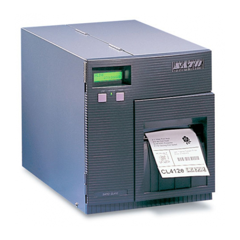
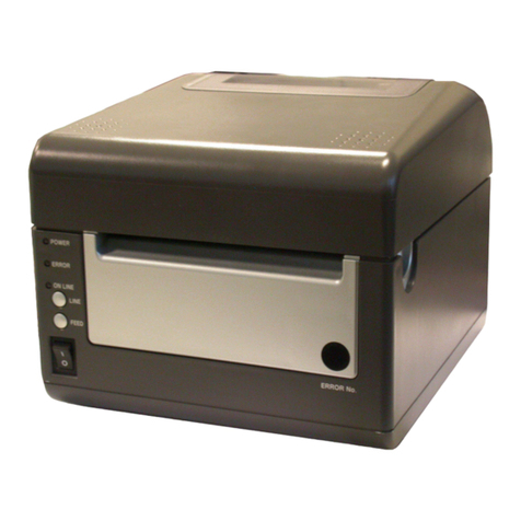
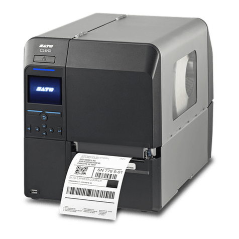
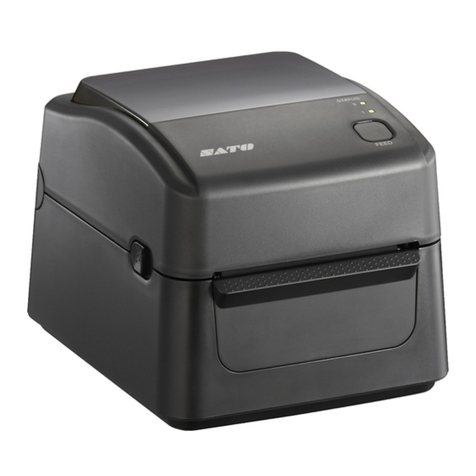
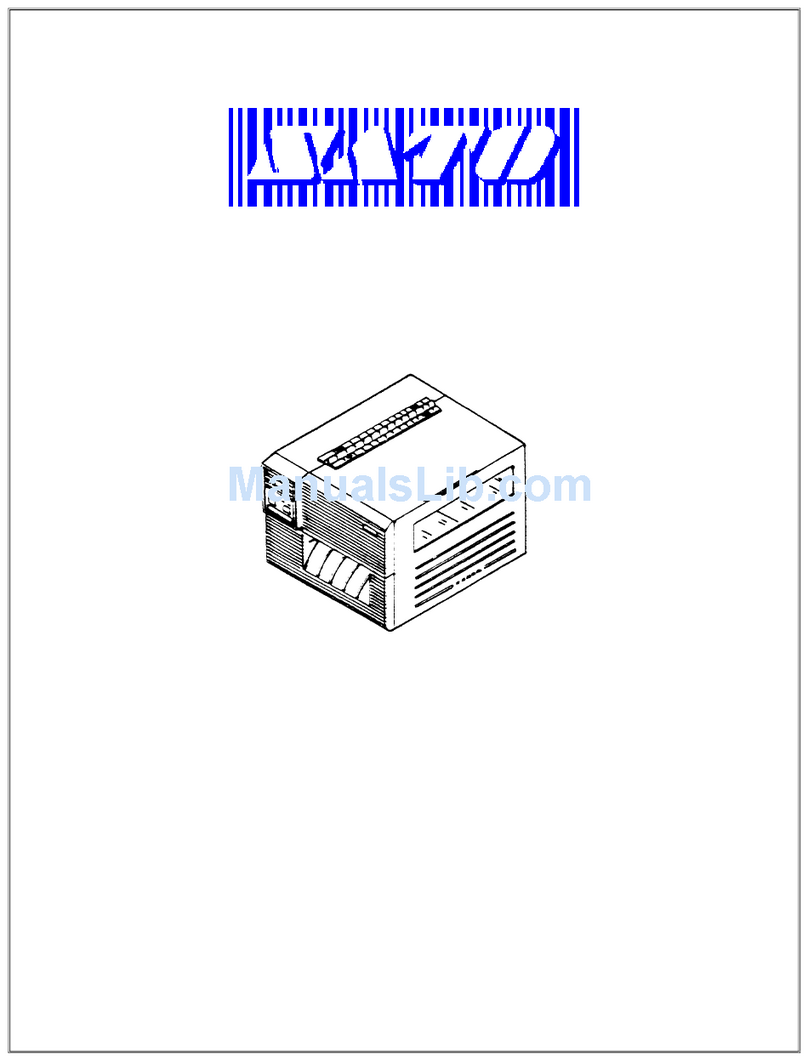
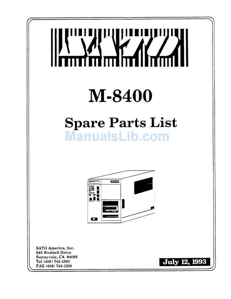
SATO CL408e User manual

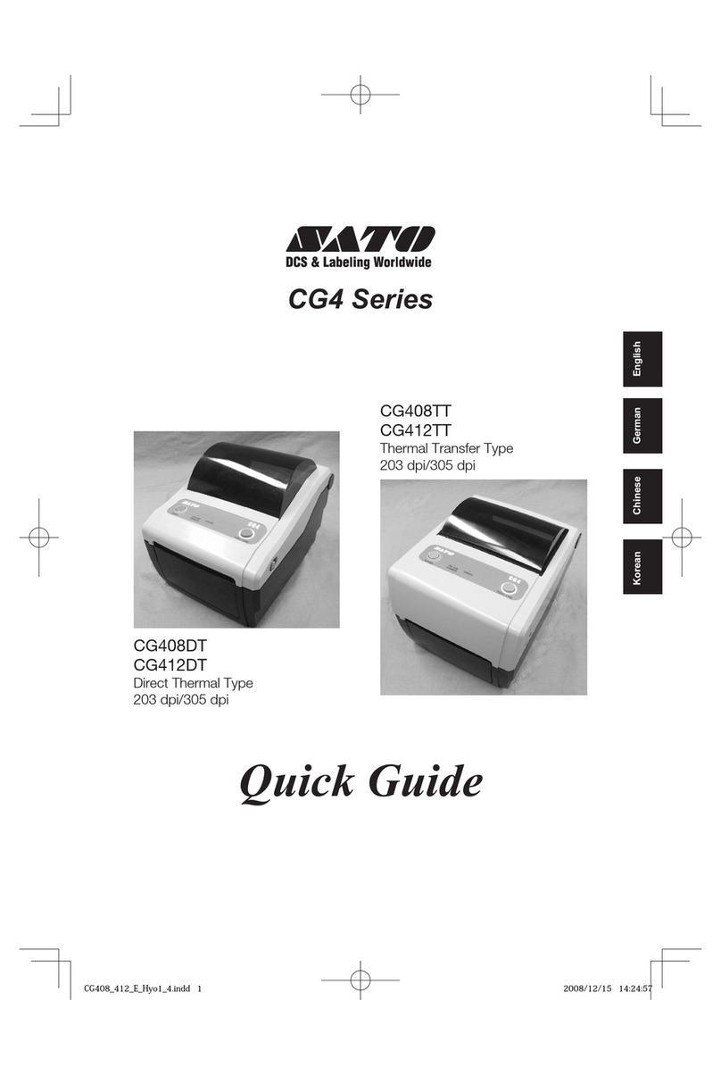
CL408e/CL412e Printers
Service Manual
PN 9001078
Rev. A
®

SATO America, Inc.
545 Weddell Drive
Sunnyvale, CA 94089
Main Phone: (408) 745-1300
Tech Support Hotline: (408) 745-1379
Fax: (408) 745-1309
http:\\www.satoamerica.com
ãCopyright 2001
SATO America, Inc.
PN 9001078
Rev. A SATO CL408e/CL412e Service Manual
The information supplied in this manual was current at time of
publication. If you come across procedures that need clarification or
Warning: This equipment complies with the requirements in Part 15 of FCC
rules for a Class B computing device. peration of this equipment in a
residential area may cause unacceptable interference to radio and TV
reception requiring the operator to take whatever steps are necessary to
correct the interference.
All rights reserved. No part of this document may be reproduced or issued to
third parties in any form whatever without the express permission of SAT
America, Inc. The materials in this document are provided for general
information and are subject to change without notice. SAT America, Inc.
assumes no responsibility for any errors that may appear.

i
PN 9001078
Rev. A SATO CL408e/CL412e Service Manual
Section 1. Overview and Specifications Page
1 Overview ........................................................................................................... 1-1
2 Physical Characteristics.................................................................................. 1-2
3 Printer Features................................................................................................ 1-3
4 Sensors ............................................................................................................. 1-6
5 Operation Panel................................................................................................ 1-7
6 Installation Considerations ............................................................................. 1-9
7 Optional Accessories ...................................................................................... 1-9
8 Environment & Approvals ............................................................................. 1-10
9 General Printer Specifications...................................................................... 1-10
10 Character Fonts.............................................................................................. 1-13
11 Bar Codes ....................................................................................................... 1-14
Section 2. Configuration
1 Dip Switch Settings .......................................................................................... 2-1
2 Default Settings ................................................................................................ 2-7
3 LCD Panel Configuration................................................................................. 2-8
Normal Mode ................................................................................................ 2-9
Advanced Mode.......................................................................................... 2-13
Card Mode................................................................................................... 2-17
Service Mode .............................................................................................. 2-25
Counters Mode ........................................................................................... 2-32
Test Print Mode........................................................................................... 2-33
Default Setting Mode ................................................................................. 2-34
Maintenance Mode — Factory Mode........................................................ 2-35
Clear Non-Standard Protocol.................................................................... 2-37
Download User Defined Protocol Codes ................................................. 2-37
Hex Dump Mode......................................................................................... 2-38
Firmware Download Mode ........................................................................ 2-39
4 Sample Test Labels ........................................................................................ 2-40
Section 3. Interface Specifications
1 Overview...........................................................................................................3-1
2 Interface Types.................................................................................................3-1
3 Receive Buffer..................................................................................................3-3
4 IEEE 1284 Parallel Interface............................................................................3-4
5 RS232C Serial Interface...................................................................................3-6
6 Universal Serial Bus (USB) Interface .............................................................3-9
7 Ethernet Interface ............................................................................................3-10
8 Bi-Directional Communications .....................................................................3-10
9 Accessory (EXT) Connector ...........................................................................3-11
Section 4. Electrical Checks and Adjustments
1 Overview ........................................................................................................... 4-1
2 Steps Prior to Some Procedures .................................................................... 4-2
3 DC Power Voltage Checks............................................................................... 4-3
4 Potentiometer Assignments & Adjustments................................................. 4-6
5a Print Position Adjustment............................................................................... 4-8
5b Print Position Adjustment............................................................................... 4-9
6 Label Gap Adjustment................................................................................... 4-10
Table of Contents

ii SATO CL408e/CL412e Service Manual PN 9001078
Rev. A
Table of Contents
Section 4. Electrical Checks and Adjustments
7 Eye-Mark Adjustment .....................................................................................4-11
8 Offset Label Stop Position Adjustment ....................................................... 4-12
9a Ribbon Sensor Operation Verification......................................................... 4-13
9b Ribbon Sensor Voltage Checking ................................................................ 4-14
10 Print Darkness Adjustment........................................................................... 4-16
Section 5. Mechanical Adjustments
1 Overview ........................................................................................................... 5-1
2 Ribbon Clutch Adjustments............................................................................ 5-2
3 Ribbon Guide Plate Adjustment ..................................................................... 5-5
4 Tear Plate Adjustment ..................................................................................... 5-6
5 Print Head Position Alignment ....................................................................... 5-7
6 Print Head Balance Adjustment...................................................................... 5-8
7 Print Head Alignment Adjustment.................................................................. 5-9
8 Timing Belt Tension Adjustment .................................................................. 5-10
Section 6. Replacement Procedures
1 Overview .......................................................................................................... 6-1
2 Replacing the Main Circuit Board.................................................................. 6-2
3 Replacing the Fuses........................................................................................ 6-7
4 Replacing the Power Supply........................................................................... 6-9
5 Replacing the Stepper Motor .........................................................................6-11
6 Replacing the Timing Belts ........................................................................... 6-12
7 Replacing the Print Head............................................................................... 6-14
8 Replacing the Platen...................................................................................... 6-17
9 Replacing the Ribbon Drive Clutch Washers .............................................. 6-19
10 Replacing the Ribbon Motion Sensor .......................................................... 6-23
11 Replacing the Label Sensor .......................................................................... 6-24
12 Replacing the Label Sensor Module ............................................................ 6-26
13 Replacing the Head Open Switch ................................................................. 6-27
14 Replacing the Display Panel PCB................................................................. 6-28
Section 7. Factory Resets
1 Overview ........................................................................................................... 7-1
2 Factory/Service Test Print ............................................................................... 7-2
3 Clear Head Counters........................................................................................ 7-3
4 Clear Dispenser Counter ................................................................................. 7-4
5 Clear Cutter Counter........................................................................................ 7-5
6 Clear EEPROM.................................................................................................. 7-6
7 Sample Test Prints ........................................................................................... 7-7
Section 8. Troubleshooting
1 Overview .......................................................................................................... 8-1
2 Initial Checklist ................................................................................................ 8-2
3 The IEEE 1284 Parallel Interface .................................................................... 8-2
4 The RS232C Serial Interface........................................................................... 8-4
5 The Universal Serial BUS (USB) .................................................................... 8-4
6 The LAN Ethernet Interface ............................................................................ 8-5
7 Error Signals .................................................................................................. 8-10
8 Troubleshooting Tables .................................................................................8-11
9 Head Pattern Examples ................................................................................ 8-15
10 Hex Dump Diagnostic Labels....................................................................... 8-17
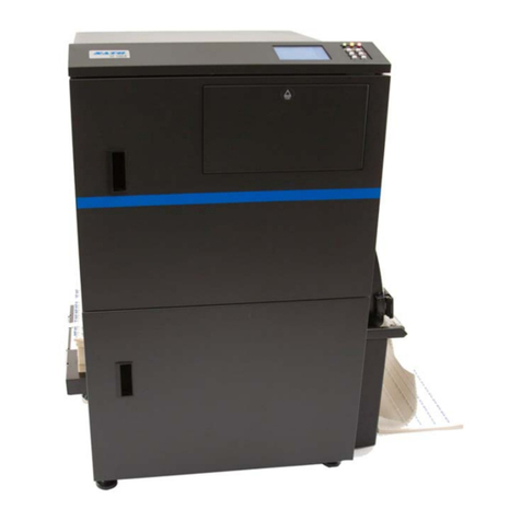
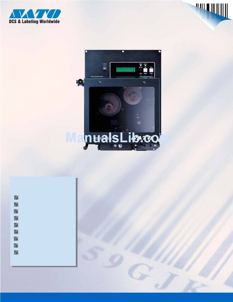
iii
PN 9001078
Rev. A SATO CL408e/CL412e Service Manual
Section 9. Optional Accessories
1 Overview .......................................................................................................... 9-1
2 Label Cutter Kit Installation............................................................................ 9-2
3 Label Dispenser Kit Installation..................................................................... 9-6
4 PCMCIA Memory Expansion Installation .................................................... 9-16
5 Flash Memory Expansion Installation ......................................................... 9-23
6 Real Time Clock Installation......................................................................... 9-26
Section 10. Parts List
1 Overview ........................................................................................................ 10-1
2 Frame Assembly............................................................................................ 10-2
3 Print Head Assembly .................................................................................... 10-5
4 Ribbon Assembly .......................................................................................... 10-9
5 Base Cover Assembly................................................................................. 10-13
6 Main PCB Assembly.................................................................................... 10-20
7 Interface Options......................................................................................... 10-21
8 PCMCIA Memory Option............................................................................. 10-22
9 Cutter Assembly Option ............................................................................. 10-23
10 Dispenser Assembly Option .......................................................................10-25
Index .............................................................................................................................. Index -1
Table of Contents

iv SATO CL408e/CL412e Service Manual PN 9001078
Rev. A
®

Page 1-1
PN 9001078
Rev. A SATO CL408e/CL412e Service Manual
Overview and Specifications
1.1 Overview
Section
The sections in this manual cover the following:
·Section 1. Overview and Specifications
·Section 2. Configuration
·Section 3. Interface Specifications
·Section 4. Electrical Checks and Adjustments
·Section 5. Mechanical Adjustments
·Section 6. Replacement Procedures
·Section 7. Factory Resets
·Section 8. Troubleshooting
·Section 9. Optional Accessories
·Section 10. Parts list
·Index
The SATO CL408e/CL412e rinters Service Manual provides information for
installing and maintaining CL408e/CL412e Thermal Transfer printers. Step-by-
step maintenance instructions are included in this manual with typical problems
and solutions. It is recommended that you become familiar with each section in
this manual before installing and maintaining the printer.
The major differences in the CL408e and the CL412e printers is the resolution of
the head. The CL408e with its 203 dpi head provides an economical labeling
solution for most applications. It can print labels up to 4.1 inches wide. The
CL412e provides a higher print resolution, 305 dpi to give laser-quality printing. It
is useful when higher resolution is needed for detailed graphic images.
The CL Series "e" printers use a subset of the standard SATO Command
Language. The CL408e/CL412e share the same command set, the only
differences are the allowable values representing the print positions on the label.
These values are specified in "dots" and will vary depending upon the resolution
of the printer and the amount of memory available for imaging the label. The
allowable range for each printer is specified in a table for those command codes.

PN 9001078
Rev. A
Page 1-2 SATO CL408e/CL412e Service Manual
Section 1. Overview and Specifications
1.2 Physical Characteristics
Width
Height
Depth
FRONT ACCESS
DOOR
TOP ACCESS
DOOR
PAPER CHECK
WINDOW
LABEL OUT
SLOT
snoisnemiDe214LCe804LC
ediW)mm172(.ni7.01
peeD)mm034(.ni9.61
hgiH)mm123(.ni6.21
thgieW)gk31(.sbl7.82
stnemeriuqeRrewoP
egatloV )%01-/+(V022-511 )%1-/+(zH06/05
noitpmusnoCrewoP eldiW05 gnitarepOW031

PN 9001078
Rev. A Page 1-3
Section 1. Overview and Specifications
SATO CL408e/CL412e Service Manual
1.3 Printer Features
INTERFACE SLOT
POWER SWITCH
PCMCIA MEMORY
EXPANSION SLOT
AC POWER INPUT
CONNECTOR
AC FUSE
EXT CONNECTOR
COVER PLATE-REMOVE FOR ACCESS
TO DISPENSER AND FAN-FOLD SLOTS
INTERFACE SLOT Slot to plug in an interface adapter. An adapter must be
connected before the printer is operational. The adapter types
available are:
RS232C Serial I/F Module, DB-25.
IEEE1284 arallel I/F Module, AM 57-40360
Universal Serial Bus I/F Module
Ethernet 10/100 BaseT I/F Module
RS-422/485 I/F Module, DB-9
MEMORY CARD SLOT One slot for optional CMCIA Memory Cards.
EXT CONNECTOR External signal connector for Accessories, AM 57-60140
POWER SWITCH Turns power On/Off
AC FUSE Input power protection. Type 3A/250V.
AC POWER INPUT Input 115V 50/60 Hz connector. Use the cable provided.
Rear Panel

PN 9001078
Rev. A
Page 1-4 SATO CL408e/CL412e Service Manual
Section 1. Overview and Specifications
FRONT ACCESS DOOR
INTERLOCK :
This switch prevents printer
operation when the Front Access
Door is open. The Top Access
Door must be open before the
Front Access Door can be opened
or closed.
FRONT ACCESS
DOOR OPEN
LEVER
TOOL FOR
DARKNESS
ADJUSTMENT
COVER OPEN SENSOR:
When this sensor is activated, the
printer will not operate and
Cover Open message will be
displayed on the display panel.
HEAD OPEN LEVER:
When the print head is
opened, this switch is
activated and the printer
will stop printing.
Printer Features
FRONT ACCESS
DOOR OPENED
RIBBON SUPPLY
SPINDLE
RIBBON REWIND
SPINDLE
PRINT HEAD
ASSEMBLY UNIT
TEAR OFF
PLATE
BRUSH
(ATTACHED TO
DOOR)

PN 9001078
Rev. A Page 1-5
Section 1. Overview and Specifications
SATO CL408e/CL412e Service Manual
MEDIA HOLDER
LABEL GUIDE
Printer Features
ACCESS PLATE
FOR OPTIONAL
LABEL
DISPENSER

PN 9001078
Rev. A
Page 1-6 SATO CL408e/CL412e Service Manual
Section 1. Overview and Specifications
RIBBON MOTION SENSOR:
This sensor is a motion detector that
signals the printer when the ribbon
supply is turning. This sensor is used
for both the ribbon end and ribbon
near end sensing.
LABEL SENSOR:
Both the "Eye-Mark" (reflective) and Gap
(transmissive) sensors can be adjusted over
a limited range. They are both located in
the label sensor unit. The assembly can be
adjusted by loosening the green sensor
knob located underneath the label transport
assembly and sliding the label sensor unit
to the desired position. The gap sensor can
be adjusted from a minimum of 0.67 in.
(17mm) to a maximum of 2.5 in. (64mm)
and the "Eye-Mark" from a minimum of
0.25 in. (6mm) to a maximum of 2.1 in.
(53mm) from the fixed position, "inside
label guide".
1.4 Sensors

PN 9001078
Rev. A Page 1-7
Section 1. Overview and Specifications
SATO CL408e/CL412e Service Manual
*NOTE: Optional RS232 Communication Card contains DSW1 switches which are
configured when supplied with the printer.
1.5 Operation Panel
LCD DISPLAY
PANEL
TWO-COLOR
STATUS LED
FEED KEY
PRINT/OFFSET/PITCH
POTENTIOMETERS
OPTION
CONNECTIOR
LABEL TAKEN LED
LINE KEY
*DSW2 & 3
LABEL TAKEN THRESHOLD
POTENTIOMETER
The CL408e/CL412e Operator anel consists of one two-color (red and green) LED
indicator, two momentary contact switches, two DI switches (a third is located on the
RS232 interface card), four adjustment potentiometers and one LCD display. All of
these are accessible from the front of the printer, however some are not accessible
unless the front cover is open. They are used to set the printer operating parameters
and to indicate the status of the printer to the operator.

PN 9001078
Rev. A
Page 1-8 SATO CL408e/CL412e Service Manual
Section 1. Overview and Specifications
Operation Panel
LCD DISPLAY PANEL 2 Line x 16 Character LCD display. Used for setting operational
parameters of the printer.
STATUS LED Two-color (Red, Green) LED that indicates the following status
conditions.
Green-Illuminated when printer is ready to receive data.
It is turned on and off by toggling the LINE key.
Red-Illuminated when there is a system fault such as an
open print head.
LINE KEY Momentary switch. ressing this key toggles the printer between
the on-line and off-line mode. When the printer is on-line, it is
ready to receive data from the host. This key acts as a pause
during a print job by taking the printer off-line. It can also be
used as a AUSE function key to stop label during the printing
process.
FEED KEY Momentary switch. ressing this key feeds one blank label
through the printer when it is off-line. When the printer is on-
line, there is a user selectable option in the Service Mode (see
page 2-28) to either print a copy of the previously printed label
or feed a blank label. The default is to feed a blank label.
POTENTIOMETERS
PRINT Located behind the Front Access Door. otentiometer is used to
adjust print darkness (fine tuning).
OFFSET Located behind the Front Access Door. otentiometer is used to
adjust amount of back/forward feed for dispenser/cutter/tear-off
bar position (+/- 3.75mm).
PITCH Located behind the Front Access Door. otentiometer is used to
adjust home position of the label (+/- 3.75mm). Affects stop
position of label feed, print position and dispense position.
LABEL TAKEN Located behind the Front Access Door. otentiometer is used to
adjust the sensing level of the Label Taken Sensor. Active only
when the Label Dispense option is installed.
DSW2 & DSW3 Located behind the Front Access Door. DI switch array to set
operational parameters of the printer. DSW1 is used to set the
RS232 parameters and is located on the RS232 interface board if
installed in your printer.
OPTIONAL Located behind the Front Access Door. This connector is used for
the cutter and dispenser optional accessories.
LABEL TAKEN LED Located behind the Front Access Door. This LED is illiminated
when a label is not present in the Label Taken Sensor. If it is not
illuminated, a label has been detected in the sensor and printing
will be inhibited until it is removed. This LED is active only
when the Label Dispense option is installed.
CONNECTOR
THRESHOLD

PN 9001078
Rev. A Page 1-9
Section 1. Overview and Specifications
SATO CL408e/CL412e Service Manual
1.6 Installation Considerations
rinter operation can be affected by the printer environment. The location of the
printer should be free from dust, humidity and sudden vibrations. To obtain optimum
results from the printer, avoid locations influenced by:
Direct or bright sunlight, since bright light will make the label sensor less responsive
and may cause the label to be sensed incorrectly.
Warm temperatures which can cause electrical problems within the printer. (See
Section 1-8 Environment.
1.7 Optional Accessories
YROSSECCA214LC/804LC
noisnapxEyromeM
4rohsalFBM61otpu(sdraCyromeMAICMCProftolsenO rofdesuebnaC.MORhsalFlanretniBM4ro/dna)MARSBM dnaegarotstamrof,noisnapxereffubtnirp,egarotselifcihparg .stnofepyTeurTdedaolnwod
radnelaC otdesuebnactahtpihcemiT/etaDdetnuomyllanretninA .gnitnirpfoemitehttaslebalpmatsemit/etad
rettuClebaL tatucebotslebalgniwollatnemhcattadetnuomyllanretninA .gnimmargorphguorhtdellortnoC.slanretnideificeps
resnepsiDlebaL rofgnikcabmorfdeleepotslebalgniwollatnemhcattalanretnI .pu-ekatgnikcablanretnI.noitacilppa)dnamedno(etaidemmi
redniweRlebaL erayehtretfalloraotnoslebalsdniwertahtnoitpolanretxE .detnirp
ecafretnIlellaraPeludoMecafretnIlellaraP4821EEEI
ecafretnIlaireSeludoMecafretnI232SRlaireSdeepShgiH
F/IlaireSlasrevinUeludoMecafretnIBSU
ecafretnItenrehtEeludoMecafretnITesaB001/01
ecafretnIxaniwT/xaoC
2-7823MBInasetalumeF/IxaoC.eludoMecafretnIxairT/xaoC F/IxaniwT.rotcennocCNBAepyTdradnatsahtiwretnirp -otuahtiwsretnirp4124ro6225,5225,4225MBIsetalume seitilibapacurht-elbac/etanimret
*
*
*
Check with your software vendor to make sure these functions are supported.
*

PN 9001078
Rev. A
Page 1-10 SATO CL408e/CL412e Service Manual
Section 1. Overview and Specifications
1.8 Environment & Approvals
1.9 General Printer Specifications
noitacificepSe804LCe214LC
aideM
htdiWmuminiM)mm22(.ni78.
htgneLmuminiM)mm6(.ni42.
htdiWmumixaM)mm131(.ni1.5
epyT suounitnoCrokcotSgaT,dloF-naF,slebaLtuCeiD
repilaC)mm52.(.ni010.
)xam(DOlloRdniWni-ecaF,)mm812(.ni6.8
)nim(DIeroC)mm83(.ni5.1
)dednemmoceR(DIeroC)mm67(.ni3
latnemnorivnE e214LC/e804LC
erutarepmeTgnitarepO14
0
401ot
0
5(F
0
04ot
0
)C
erutarepmeTegarotS0-
0
401ot
0
02-(F
0
04ot
0
)C
ytidimuHgnitarepOgnisnednoc-non,HR%58-51
ytidimuHegarotSgnisnednoc-non,HR%09xaM
egrahcsiDcitatsortcelEVK8
slavorppAyrotalugeR
ytefaSASC,LU
IME/IFRAssalCCCF
noitacificepSe804LCe214LC
tnirP
dohteMrefsnarTlamrehTrotceriD
)elbatceleSresU(deepSs/mm051ot05-spi6ot2
)eziStoD(eludoMtnirPmm521.-.ni9400.mm380.-.ni3300.
noituloseRmmpd8-ipd302mmpd21-ipd503
htdiWtnirPmumixaMmm401-.ni1.4
htgneLtnirPmumixaMmm9421-.ni2.94mm338-.ni8.23

PN 9001078
Rev. A Page 1-11
Section 1. Overview and Specifications
SATO CL408e/CL412e Service Manual
General Printer Specifications
noitacificepSe804LCe214LC
gnisneS
urht-eeSevissimsnarTelbavoM
kraM-eyEevitcelfeRelbavoM
mroFsuounitnoCdesutonrosneS
nobbiR
htdiWmumixaM)mm111(.ni4.4
htgneL)m054(.tf5741
ssenkcihTdniWniecaF,norcim5.4
slangiSdnaslortnoC
DELeniL-nOneerG=sutatS
)1(
DELrewoPenoN
DELtuOaideMdeR=sutatS
)1(
DELtuOnobbiRdeR=sutatS
)1(
DELrorrEdeR=sutatS
)1(
lenaPDCLretcarahC61xeniL2
hctiwSeniL-ffO/nOlenaPtnorF
hctiwSdeeFlebaLlenaPtnorF
hctiwSffO/nOrewoPlenaPraeR
stnemtsujdAretemoitnetoP
ssenkraDtnirPlenaPtnorF
hctiPlenaPtnorF
tesffOlenaPtnorF
yalpsiDenoN
(1) Single two color (Red, Green) LED

PN 9001078
Rev. A
Page 1-12 SATO CL408e/CL412e Service Manual
Section 1. Overview and Specifications
General Printer Specifications
noitacificepSe804LCe214LC
seludoMecafretnI
lellaraPlellaraP4821EEEI
laireS
locotorPlaireS
)spb006,75ot0069(C232SR )spb006,75ot0069(584/224SR
)ysuB/ydaeR(lortnoCwolFerawdraH )ffO-X/nO-X(lortnoCwolFerawtfoS 4ro3,2sutatSlanoitcerid-iB
suBlaireSlasrevinU1.1noisreVBSU
tenrehtETesaB001/01
noissimsnarTataDtamroFIICSA
gnissecorP
UPCCSIRtiB23
MORhsalFBM2
MARDSBM61
reffuBevieceRBM59.2
MORhsalFlanoitpOBM4
yromeMAICMCPlanoitpOMARSBM4rohsalFBM61otpU

PN 9001078
Rev. A Page 1-13
Section 1. Overview and Specifications
SATO CL408e/CL412e Service Manual
1.10 Character Fonts
noitacificepSe804LCe214LC
stnoFxirtaM
tnoFU)Hstod9xWstod5(
tnoFS)Hstod51xWstod8(
tnoFM)Hstod02XWstod31(
tnoFUXacitevleH)Hstod9xWstod5(
tnoFSX dloBdesnednoCsrevinU)Hstod71xWstod71(
tnoFMX dloBdesnednoCsrevinU)Hstod42xWstod42(
tnoFAOA-RCO)Hstod22xWstod51(A-RCO)Hstod33xWstod22(
tnoFBOB-RCO)Hstod42xWstod02(B-RCO)Hstod63xWstod03(
stnoFgnihtoomSotuA
BW)Hstod03xWstod81(tnoFBW
LW)Hstod25xWstod82(tnoFLW
BX dloBdesnednoCsrevinU)Hstod84xWstod84(tnoFBX
LX fireSsnaS)Hstod84xWstod84(tnoFLX
tnoFrotceV
gnicapSdexiFrolanoitroporP stod999x999otstod05x05eziStnoF snoitairaVtnoF01,acitevleH
stnoFretsaRAFGA
tnoFAtp27ot8,semiTGC
tnoFBtp27ot8,etarivmuirTGC
stnoFelbadaolnwoD
margorPytilitUhtiwstnoFepyTeurTdeppaMtiB
lortnoCretcarahC
setanidroocYroXehtrehtieniX21otpunoisnapxE lortnochctiPretcarahC lortnocecapSeniL ytilicaftnirPlanruoJ
0
0
09,
0
081,
0
072dna
0
noitatoR
®

PN 9001078
Rev. A
Page 1-14 SATO CL408e/CL412e Service Manual
Section 1. Overview and Specifications
1.11 Bar Codes
noitacificepSe804LCe214LC
seigolobmyS
)latnemelppuSNAE/CPU(dnalkooB 31-NAE,8-NAE RABADOC 93edoC 39edoC 821edoC 5fo2devaelretnI 5fo2lairtsudnI 5fo2xirtaM ISM TENTSOP 821-NAE/CCU E-CPUdnaA-CPU
soitaR shtdiwrabelbanifedresU5:2,3:1,2:1
thgieHraBelbammargorpresU,stod006ot4
noitatoR0
0
09,
0
081,
0
072dna
0
serutaeFrehtO
gnirebmuNlaitneuqeS sedocrabdnasciremunhtobfognirebmunlaitneuqeS
sretcarahCmotsuCsretcarahclaicepsrofegarotsMAR
scihparG XCP.roPMB.,yraniB/xeHOTAS,scihpargelbasserddatodlluF stamrof
yalrrevOmroF stamrofxelpmocfognitidedeeps-hgihrofyalrevomroF
Other manuals for CL408e
9
This manual suits for next models
1
Table of contents
Other SATO Printer manuals

SATO
SATO CL4NX RIDF User manual

SATO
SATO GZ4e Series User manual

SATO
SATO M 8400S Guide

SATO
SATO CL408e User manual

SATO
SATO CL408e User manual

SATO
SATO ARGOX OS-214EX User manual

SATO
SATO CL-408 Owner's manual

SATO
SATO Argox D4-250 User manual

SATO
SATO M-8400RV User manual

SATO
SATO M-84Pro Series User manual