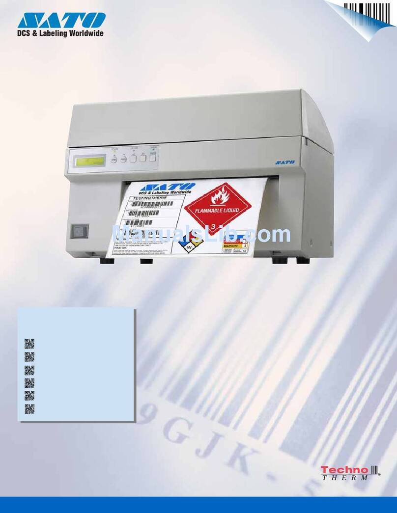
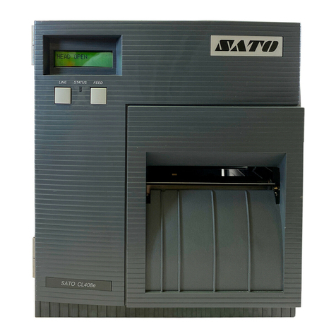
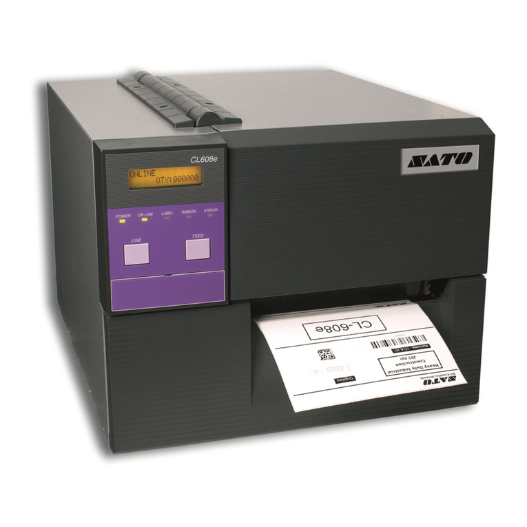
SATO CL608e Guide

CL608e/612e
Mechanical Adjustments
SATO CL608/CL612 printers contain adjustable sub-assemblies. T is means t at during
your regular maintenance, your service tec nicians are able to make adjustments to
reset t e printer to factory specifications t ereby ensuring optimum performance of
your printer.
T e main mec anical sub-assemblies are:
•Ribbon Unwind/Rewind Assembly's
•Ribbon Guide Roller Assembly
•Print Head Assembly
•Drive Belt Assembly's
In t is section you will find procedures for:
•Ribbon Unwind/Rewind Clutch Adjustment
•Print Head Position Adjustment
•Print Head Balance Adjustment
•Ribbon Roller Adjustment
•Ribbon Tension Balance Adjustment
•Feed Roller Adjustment
•Timing Belt Tension Adjustment
•Head Latch Adjustment
•Notch/Gap Sensor Adjustment
SATO America, Inc
545 Weddell Drive
Sunnyvale, CA 94089
Main Phone: (408) 745-1300
Tech Support Hotline: (408) 745-1379
Fax: (408) 745-1309
®
Proc 64

2SATO CL608e/CL612e Mechanical Adjustments
Excessive ribbon unwind and rewind tension will result in variable ribbon motion and
could be t e cause of print quality problems.
Follow t e procedures 1 and 2 to verify t at t e ribbon unwind and rewind tensions are
wit in specifications or if adjustment of eit er clutc is necessary.
Proc 1 Ribbon Unwind Clutch Adjustment
Required Equipment: 1 Kg Tension Gauge
Ribbon Core, empty
String
12mm Wrenc
#2 Pozidrv Screwdriver
STEP PROCEDURE
1. Connect t e power cable to t e printer and AC outlet. Turn t e printer
ON.
2. Raise t e access door and remove t e ribbon and label stock if installed.
Fig. 1
3. Attac string to an empty ribbon core and place on t e Ribbon Unwind
Spindle. Wind t e string tig tly around t e ribbon core in a single layer
and in a clockwise direction. Attac t e free end of t e string to t e
tension gauge. Fig. 2 & 3
4. Gradually lift t e tension gauge, pulling t e string to unwind it from t e
core. Once t e spindle begins to move, t e gauge s ould indicate 450 to
550 grams of tension. Excessive or insufficient tension must be corrected
by adjusting t e Ribbon Unwind Clutc . Fig. 2 & 3
5. To adjust t e clutc , loosen t e locking screw and move t e adjust nut CW
for more tension and CCW for less tension. Tig ten t e locking screw and
repeat Steps 3 and 4 until t e correct tension is ac ieved.
Fig. 1
REMOVE THE
RIBBON AND
LABEL STOCK
Ribbon Clutch Adjustments

3
SATO CL608e/CL612e Mechanical Adjustments
Ribbon Clutch Adjustments
Fig. 3
RIBBON UNWIND
SPINDLE
ADJUST NUT
LOCKING SCREW IS
INSIDE ADJUST NUT
950-1050g
REWIND
STRING
EMPTY RIBBON
CORES
RIBBON REWIND
SPINDLE
Fig. 4
Fig. 2
450-550g
UNWIND
TENSION GAUGE
TENSION GAUGE
STRING
REWIND CLUTCH UNWIND CLUTCH

4SATO CL608e/CL612e Mechanical Adjustments
STEP PROCEDURE
1. Connect t e power cable to t e printer and AC outlet. Turn t e printer
ON.
2. Raise t e access door and remove t e ribbon and label stock if installed.
Fig. 1
3. Attac string to an empty ribbon core and place on t e Ribbon Rewind
Spindle. Wind t e string tig tly around t e ribbon core in a single layer
and in a clockwise direction. Attac t e free end of t e string to t e
tension gauge. Fig. 2 & 4
4. Gradually lift t e tension gauge, pulling t e string to unwind it from t e
core. Once t e spindle begins to move t e gauge s ould indicate 950 to
1050 grams of tension. Excessive or insufficient tension must be corrected
by adjusting t e ribbon unwind clutc . Fig. 2 & 4
5. To adjust t e clutc , loosen t e locking screw and move t e adjust nut CW
for more tension and CCW for less tension. Tig ten t e locking screw and
repeat Steps 3 and 4 until t e correct tension is ac ieved.
Proc 2 Ribbon Rewind Clutch Adjustment
Ribbon Clutch Adjustments

5
SATO CL608e/CL612e Mechanical Adjustments
STEP PROCEDURE
1. Run a test print. Fig. 5
2. By adjusting t e Allen ead screws on t e rear of t e Stay, you can move
t e print ead forward or backward. T is allows you to position t e
burnline of t e print ead directly and evenly over t e apex of t e platen
surface. Fig. 6 & 7
3. W ile printing t e test pattern, adjust t e Allen adjustment screws for t e
best print quality. NOTE: It is vital t at a known good platen be in t e
unit.
4. Verify t e image is even on t e label by measuring t e distance from t e
bottom of t e barcode to t e bottom of t e label on bot sides. Refer to
Fig. 5. If uneven, adjust t e Allen adjustment screws to correct t e
alignment. T is may affect t e print quality and may need to be
readjusted.
5. If you are unable to get t e unit to produce good print quality, proceed to
Print Head Balance Adjustment and perform t e adjustment; t en return
to t is section and redo t e Print Head Position Adjustment. NOTE: You
may ave to do bot of t ese adjustments concurrently several times to
ac ieve proper print quality and alignment.
Required Equipment: Allen Wrenc 2.5mm
Ruler
5.3 Print Head Position Adjustment

6SATO CL608e/CL612e Mechanical Adjustments
Print Head Position Adjustment
ALLEN WRENCH ADJUST SCREWS
Fig. 7
STAY
STAY Fig. 6
NELLAFONOITATOR HCNERW DAEHTNIRPFOTNEMEVOM
ESIWKCOLCTNORFEHTOT
ESIWKCOLC-RETNUOCDRAWKCAB
TURN SCREWS
CW/CCW
TEST PRINT Fig. 5
MEASURE FROM
BOTTOM OF BARCODE
TO BOTTOM OF LABEL
MEASURE FROM
BOTTOM OF BARCODE
TO BOTTOM OF LABEL

7
SATO CL608e/CL612e Mechanical Adjustments
Print Head Balance Adjustment
Required Equipment: #2 Pozidrv Screwdriver
10mm wrenc
STEP PROCEDURE
1. Connect t e power cable to t e printer and AC outlet. Turn t e printer
ON.
2. Raise t e access door and load t e ribbon and label stock.
NOTE: It is vital t at a known good platen be in t e unit.
3. Loosen t e locking screws. Fig. 8
4. W ile printing, adjust t e eccentric wit a 10mm wrenc . Turn t e
eccentric clockwise to increase t e density (darker impression) of t e inner
side of t e image or counter-clockwise to increase t e density (darker
impression) of t e outer side of t e image.
5. Hold t e eccentric in place wit t e 10mm wrenc and tig ten t e locking
screws loosened in Step 3 above.
6. After adjustment, verify t at label and ribbon are still tracking correctly.
7. If you are unable to get t e unit to produce good print quality, return to
Print Head Position Adjustment and perform t e adjustment; t en return to
t is section and redo t e Print Head Balance Adjustment. NOTE: You
may ave to do bot of t ese adjustments concurrently several times to
ac ieve proper print quality and alignment.
NOTE: On t is printer, t e platen roller under t e print ead is adjustable wit an
eccentric to make print quality and pressure consistent across t e label.
LOCKING
SCREWS
ADJUST PLATE
Fig. 8
ECCENTRIC

8SATO CL608e/CL612e Mechanical Adjustments
Required Equipment: #2 Pozidrv Screwdriver
10mm wrenc
STEP PROCEDURE
1. Connect t e power cable to t e printer and AC outlet. Turn t e printer
ON.
2. Raise t e access door and load t e ribbon and label stock. Fig. 1
3. Loosen t e locking screws. Fig. 9
4. Turn eccentric wit wrenc .
5. W en t e carbon ribbon moves evenly wit out wrinkling, tig ten t e
locking screws.
LOOSEN
LOCKING
SCREWS
TURN ECCENTRIC
Fig. 9
NOTE: Only do t is adjustment after adjusting ribbon wind and
unwind tension.
Ribbon Roller Adjustment

9
SATO CL608e/CL612e Mechanical Adjustments
Ribbon Tension Balance Adjustment
Required Equipment: #2 Pozidrv Screwdriver
Flat Blade Screwdriver
STEP PROCEDURE
1. Connect t e power cable to t e printer and AC outlet. Turn t e printer ON.
2. Remove (3) screws olding t e left side cover to t e printer. Raise t e
access door and loosen t e (2) screws on t e inside top of t e printer. Lift
off t e left side cover. Fig. 11
3. Unload t e ribbon and label stock.
4. Refer to Figs. 12.
Ribbon Rewind Spindle A must be parallel wit Ribbon Roller B.
Ribbon Rewind Spindle C must be parallel wit Ribbon Roller D.
Loosen (2) locking screws astride s afts A & B. Insert a flat blade screw
driver into eac slot and adjust until s afts are parallel wit ribbon rollers B
& D. Tig ten t e locking screws astride s afts.
5. Rec eck t e ribbon alignment and printouts. If necessary, redo step 4.
NOTE: T is procedure s ould only be attempted by a qualified tec nician.
T e ribbon s ould flow evenly along t e lengt of t e STAY to avoid ribbon
wrinkles and maintain optimum print quality. If ribbon wrinkles appear as
in Fig. 10, perform t e following steps:
NOTE: Only do t is adjustment after adjusting ribbon
wind and unwind tension.
RIBBON REWIND
SPINDLE
RIBBON UNWIND
SPINDLE
RIBBON SHOWN
WITH WRINKLES
STAY
Fig. 10

10 SATO CL608e/CL612e Mechanical Adjustments
Ribbon Tension Balance Adjustment
Figs. 12
ADJUST PLATES
MOVE THE ADJUST
PLATES UP/DOWN
LOCKING SCREWS
A
RIBBON ROLLER
RIBBON REWIND
SPINDLE
RIBBON ROLLER
RIBBON REWIND
SPINDLE
STAY
"A" MUST BE
PARALLEL
WITH "B"
"C" MUST BE
PARALLEL
WITH "D"
Fig. 11
D
C
B
REMOVE (3) SCREWS
RAISE THE ACCESS DOOR
AND LOOSEN (2) SCREWS
ON THE INSIDE TOP OF
THE PRINTER

11
SATO CL608e/CL612e Mechanical Adjustments
Feed Roller Adjustment (Label Tracking)
Required Equipment: #2 Pozidrv Screwdriver
5.5mm wrenc
1 Kg Tension Gauge
STEP PROCEDURE
1. Switc t e printer OFF and disconnect t e power cable.
2. Raise t e access door and remove t e label stock if installed. Fig. 1
3. Attac a strip of 20mm + wide liner backing paper to t e end of t e
tension gauge. Under t e media cover, place t e strip between t e pressure
rollers at one end wit t e print ead assembly open. Gradually pull t e
tension gauge and measure t e friction. Repeat at t e opposite end of t e
rollers. Fig. 13 & 14
4. T e difference between t e left side and t e rig t side s ould be 100g or
less.
5. To adjust t e pressure between t e rollers, loosen t e two fixing nuts wit
a 5.5mm wrenc and adjust t e screws. Fig. 15
6. To adjust t e alignment of t e roller, loosen t e locking screw and move
t e adjust plate wit a screwdriver until t e required positions are found.
Fig. 16
7. Tig ten t e locking screw.
Used for fine tuning. Adjusts pressure between upper and lower rollers.

12 SATO CL608e/CL612e Mechanical Adjustments
ADJUST SCREW & FIXING
NUT ON BOTH ENDS OF
MEDIA COVER
Fig. 13
ADJUST
PLATE
Fig. 14
Fig. 15
Fig. 16
TENSION
GAUGE
BACKING PAPER
LEFT SIDE
MEDIA
LID
PULL
BACKING PAPER
RIGHT SIDE
PULL
MOVE WITH
FLAT BLADE
SCREWDRIVER
LOCKING SCREW
Feed Roller Adjustment (Label Tracking)

13
SATO CL608e/CL612e Mechanical Adjustments
Timing Belt Tension Adjustment
STEP PROCEDURE
1. Remove (3) screws olding t e left side cover to t e printer. Raise
t e access door and loosen t e (2) screws on t e inside top of t e
printer. Lift off t e left side cover. Fig. 11
2. Loosen t e locking screws and belts will self-adjust. Tig ten, but do
not overtig ten t e screws. Fig. 17
3. Replace t e left side cover.
ADJUSTMENT
SPRING
LOCKING
SCREWS
TIMING BELT "B"
Fig. 17

14 SATO CL608e/CL612e Mechanical Adjustments
LATCHED
POSITION
UNLATCHED
POSITION
Pairs of set-screws on
each end of shaft must
be tightened to avoid
slippage of media and
light printing on the left
side of the labels
The set-screws which attach the head latches to the latch shaft can become loosened
during the operation of your printer. If you notice light printing on the left side of
your labels, check the pairs of set-screws to be sure they are securely tightened.
To correct t is problem:
Close t e print ead and pull bot latc es so t ey are fully engaged to t e latc
posts. Tig ten (2) set screws per latc .
Head Latch Adjustment

15
SATO CL608e/CL612e Mechanical Adjustments
Notch/Gap Sensor Adjustment
T e CL-608e/612e printers can position labels using eit er a label gap (transmissive)
or a Eye-Mark (reflective) sensor. T e sensor used is selected by DSW2-2. (page 2-3)
T e gap sensor position can be adjusted over a limited range.
LOOSEN ADJUSTMENT
SCREW AND REPOSITION
IN SLOT. TIGHTEN SCREW
LABEL FEED
DIRECTION
INSIDE EDGE
OF PRINTER
1" (25 mm)
Minimum
12345678901234567890123456
1
234567890123456789012345
6
1
234567890123456789012345
6
1
234567890123456789012345
6
1
234567890123456789012345
6
1
234567890123456789012345
6
12345678901234567890123456
NOTCH/GAP SENSOR
ADJUSTMENT RANGE
NOTCH/GAP LOCATIONS
(MAXIMUM & MINIMUM)
3.5" (90 mm) Maximum
.33" (9 mm) Eye-Mark
Sensor Location
(shown for ref. only)
EYE - MARK Minimum Size
.12" (3 mm) W x .24" (6 mm) L
LABEL
MINIMUM INTER-LABEL
GAP .012" (3 mm)
Other manuals for CL608e
2
This manual suits for next models
1
Table of contents
Other SATO Printer manuals

SATO
SATO M-5900 User manual

SATO
SATO M-8490Se Series User manual

SATO
SATO CX208/212 Operating instructions

SATO
SATO LM408e User manual

SATO
SATO D508 User manual

SATO
SATO Argox D4-280plus User manual

SATO
SATO M-8459Se Series User manual

SATO
SATO M10e Series User manual

SATO
SATO WS408TT User manual

SATO
SATO LP 100R L Manual