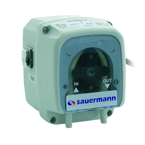
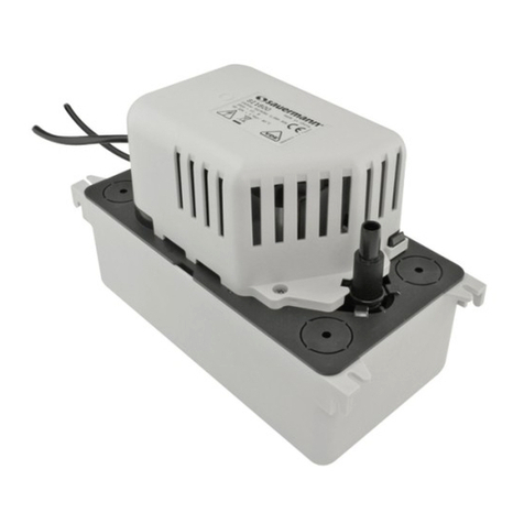
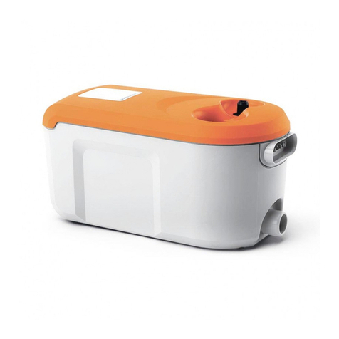
sauermann SI 1806 kit User manual
Other sauermann Water Pump manuals

sauermann
sauermann Si-82 User manual
sauermann
sauermann Si-10 User manual

sauermann
sauermann SI1082SIUN23 User manual

sauermann
sauermann Si-1830 User manual

sauermann
sauermann OMEGA PACK Si-20 User manual

sauermann
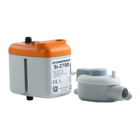
sauermann Si-10 User manual
sauermann
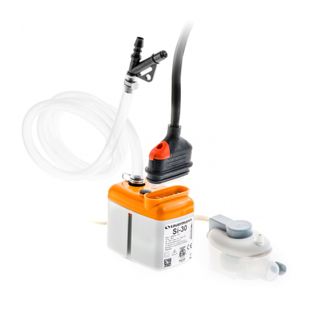
sauermann Si-30 User manual
sauermann
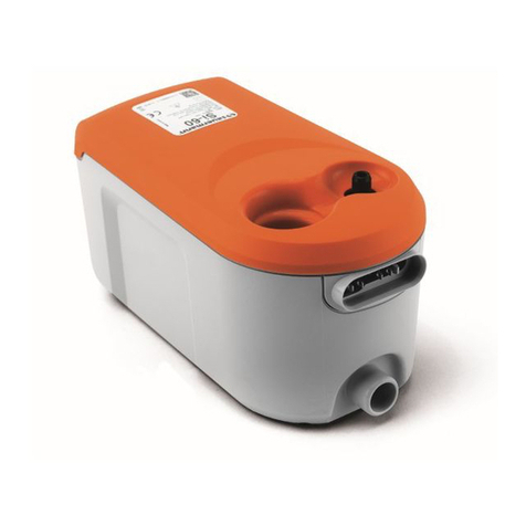
sauermann Si-60 User manual
sauermann
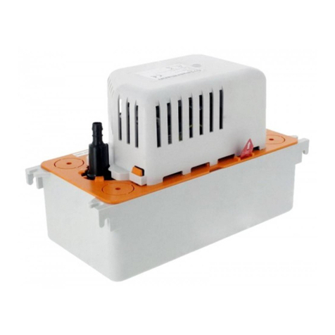
sauermann Si-30 Detect + User manual
sauermann
sauermann Si-82 User manual

sauermann
sauermann Si-10 User manual

sauermann
sauermann SI1805 User manual

sauermann
sauermann SI 3080 User manual
sauermann
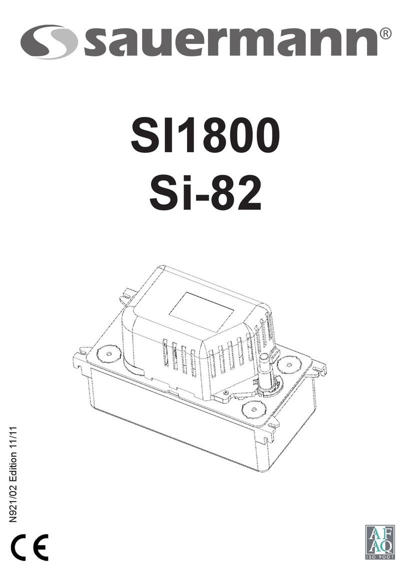
sauermann SI 1800 User manual

sauermann
sauermann SI1082SIUN23 User manual
sauermann
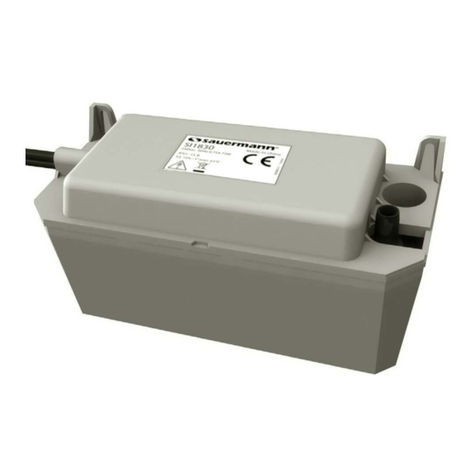
sauermann Si-1830 User manual
sauermann
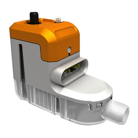
sauermann Si-10 User manual

sauermann
sauermann Si-61 User manual

sauermann
sauermann OMEGA PACK Si-20 User manual
sauermann
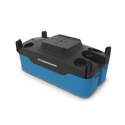
sauermann Si-83 Series User manual
Popular Water Pump manuals by other brands

Watershed Innovations
Watershed Innovations HYDRAPUMP SMART FLEX Instructional manual

Graco
Graco Modu-Flo AL-5M instructions

Messner
Messner MultiSystem MPF 3000 operating instructions

Xylem
Xylem Bell & Gossett WEHT0311M Installation, operation and maintenance instructions

WilTec
WilTec 50739 Operation manual

Franklin Electric
Franklin Electric Little Giant 555702 HRK-360S instruction sheet

Ingersoll-Rand
Ingersoll-Rand PD02P Series Operator's manual

VS
VS ZJ Series Operating instruction

Flotec
Flotec FPZS50RP owner's manual

SKF
SKF Lincoln FlowMaster II User and maintenance instructions

Xylem
Xylem Lowara LSB Series Installation, operation and maintenance instructions

Water
Water Duro Pumps DCJ500 Operating & installation instructions

Action
Action P490 Operating instructions & parts manual

Flo King
Flo King Permacore Reusable Carbon Bag Disassembly. & Cleaning Instructions

ARO
ARO ARO PD15P-X Operator's manual

Pumptec
Pumptec 112V Series Operating instructions and parts manual

Virax
Virax 262070 user manual

Neptun
Neptun NPHW 5500 operating instructions
