manuals.online logo
Brands
  1. Home
  2. •
  3. Brands
  4. •
  5. sauermann
  6. •
  7. Water Pump
  8. •
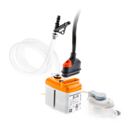
  9. sauermann Si-30 User manual

sauermann Si-30 User manual

Avant toute installation, maintenance ou
démontage, mettre impérativement l’ensemble de l’ins-
tallation hors tension. Le bloc pompe ne doit pas être
immergé, ni placé à l’extérieur des locaux ou dans des
lieux humides et doit être tenu hors gel.
Il est nécessaire de nettoyer les éléments collecteurs de
condensats (bac du climatiseur, tubes, sorties...) avant l’ins-
tallation de la pompe.
L’ensemble est équipé :
- D’une protection thermique : déclenchement à 194°F
(90°C).
- D’une enveloppe auto-extinguible (matériau
UL94 V0)
E
N739- 01 Edition 14/07
Si-30
Make certain that the entire power supply to the
unit/system is disconnected before attempting to ins-
tall, service or remove any component.
The pump unit must not be immersed in water, installed
outside the premises, stored in a damp environment or
exposed to frost.
All condensate collection elements (collection tray,
connecting tubes, outlets etc…) must be cleaned thorou-
ghly prior to installing the pump.
The pump is supplied with :
- A self-resetting thermal cut-out set at 194°F (90°C).
- A self extinguishing body case (UL94 VO Material)
FR ES
-
EN
SAFETY WARNING / AVERTISSEMENTS DE SÉCURITÉ / ADVERTENCIA
The pump unit can be installed within the air conditioning unit (A),
in an adjacent lineset cover (B) or in the plenum or ceiling space (
C)
.
Do not insulate the pump unit. Use a plenum rated equipment box to protect the
pump (UL 1995). Note: Despite a lower operating sound level, if the indoor unit is installed in
a bedroom or other sound sensitive area, the preferred installation location of the pump is in
the plenum or ceiling space (C) and not inside the indoor unit (A) nor inside the line set cover (B)
El cuerpo bomba se debe fi jar en el climatizador (A), la canaleta (B), o en el falso techo. No se debe aislar el
cuerpo bomba. Utilizar una caja de protección certifi cada plenum (UL 1995) (C). Nota: aunque la bomba tiene un bajo nivel
sonoro, si la unidad interna está instalada en una habitación u otro espacio sensible al ruido, es preferible ubicar la bomba entre el techo y el falso techo
(fi gura C) que en el interior de la unidad (fi gura A) o en la canaleta (fi gura B).
EN
FR
ES
Ø 1/4’’ ID
Ø 6 mm ID
I
I
II
- Dos & Dont’s
- Installation / Instalacion
- Installation options / Opciones de Instalacion / Modes d’installation
B
B
G
G
H
E
G
H
1/8’’ x 12’’
3.5 x 300 mm
C
D
E
A
B
H
G
I
5ft
1.5 m
Ø 5/32’’ x 1/4’’ - 2 15/16’’
Ø 4 x 6 mm / 75 mm
Ø 19/32’’, 1 49/64’’ x 2 3/8’’
Ø 15mm, 45x60 mm
x 6
KIT CONTENTS / CONTENU DU KIT / CONTENIDO DEL KIT
Ø1/4’’ (6mm)
L
TECHNICAL CHARACTERISTICS /
CARACTERISTIQUES TECHNIQUES /
CARACTERÍSTICAS TÉCNICAS EN
Max fl ow rate 60Hz : 5 gph (19 l/h)
Max suction head 10 ft (3 m)
Max discharge head 33 ft (10 m)
Voltage 208 - 230V~50/60Hz - 14W
Safety switch NC 8A resistive - 250 V
Thermal protection
(overheating) 194°F (90° C)
Detection levels On=5/8” Off =7/16’’ Al. =3/4’’
On: 16 mm Off: 11 mm Al: 19 mm
Sound level at 3.3 ft 20 dBA
Safety standards UL / CSA certifi ed by Intertek
FR
Débit maximal 60Hz : 5 gph (19 l/h)
Hauteur d’aspiration max. 10 ft (3 m)
Hauteur de refoulement max. 33 ft (10 m)
Alimentation électrique* 208 - 230V~50/60Hz - 14W
Contact de sécurité NF 8 A résistif - 250 V
Protection thermique
(surchauffe)
194°F (90° C)
Niveaux de détection On=5/8”Off =7/16’’
Al. =3/4’’
On:16 mmOff:11 mm Al:19
mm
Niveau sonore à 3.3ft 20 dBA
Normes de sécurité
UL / CSA certifi é par
Intertek
ES
Caudal máximo 60Hz : 5 gph (19 l/h)
Altura de aspiración máx. 10 ft (3 m)
Altura máx. de descarga 33 ft (10 m)
Tensión 208 - 230V~50/60Hz - 14W
Contacto de alarma NC 8 A resistivo - 250 V
Protección térmica
(sobrecalentamiento)
194°F (90° C)
Niveles de detección On=5/8”Off =7/16’’Al. =3/4’’
On:16 mm Off:11 mm Al:19
mm
Nivel acústico a 3.3 ft 20 dBA
Normas de seguridad UL/CSA certifi cado por
Intertek
Capacity (US gph)
Débit (l/h) - Caudal (l/h)
Hauteur de refoulement (m)
Altura máxima de descarga (m)
Discharge (ft)
04 8 1412 16 18 20
2
4
6
12
8
10
2 6 10
Flow rate - Débit
Disharge head - Hauteur de refoulement
14
3 41 2 5 5.2
(US gph)
32
30
40
20
10
(Ft)
- Installation overview / Principe d’installation / Esquema de principo
- Installation overview / Principe
d’installation / Esquema de principo - Installation / Instalacion
- Installation overview / Principe d’installation / Esquema de principo
max. 10 ft (3m)
max. 33 ft (10 m)
5 ft
(1.5m)
5 ft (1.5m)
C
A
B
A
C
C
A
C
Hung from ceiling
Suspendue
Suspendido
On linesets
Sur un tube
Sobre un tubo
Wall mounted
Au mur
En la pared
I
x4
OK OK
Asegúrese de que el suministro total de energía a la
unidad / sistema, esté desconectado antes de intentar
instalar, reparar o quitar cualquier componente.
La bomba no debe ser sumergida en agua, instalada
en el exterior, almacenada en un ambiente húmedo o
expuesta a las heladas.
Todos los elementos de la evacuación de los conden-
sados (bandeja de recogida, los tubos de conexión,
enchufes, etc....) deberán estar bien limpios antes de
instalar la bomba.
La bomba se suministra con:
- Un relé térmico automático ajustado a 194°F (90°C).
- Material auto extinguible al fuego (UL94 VO
Material)
SAUERMANN N.A. Corp.
415 Oser Avenue, Suite P,
Hauppauge, NY 11788/
USA
Tel : (+1) 631-234-7600
Fax : (+1) 631-234-7605
E-mail : [email protected]
www.sauermannpumps.us
1 2
345
J
1/10’’ x 4’’
2.5 x 100 mm
x 2
1 | DETECTION UNIT / BLOC DE DETECTION / BLOQUE DE DETECCION 2 | PUMP / POMPE / BOMBA
3 | TUBING CONNECTION / RACCORDEMENT DES TUBES / CONEXIÓN DE LOS TUBOS
Jx2
K
L
A
J
J
K
K
K
L
Ø 3/8’’
(10 mm)
Recommended
Recommandé
Aconsjado
Optional
Autorisé
Autorizado
Prohibited
Déconseillé
Desaconsejado
- Dos & Dont’s
Le bloc pompe peut être fi xé à l’intérieur du climatiseur (A), dans une goulotte adjacente (B), en faux pla fond, au
dessu s du climat iseur. Ne pas isoler le bloc pompe. Utiliser une boite de protection certifi ée plénum (selon UL 1995) (C).
Remarque : même si le niveau sonore de la pompe est faible, quand l’unité intérieure est installée dans une chambre ou tout
autre espace sensible au bruit, il est préférable de placer la pompe dans l’entre-plafond (fi gure C) plutôt qu’à l’intérieur de
l’unité (fi gure A) ou dans la goulotte (fi gure B).
min
3ft (1m)
N739_01_1407-DAIKIN.indd 1 17/02/2014 11:34:19
© 2013 Sauermann® all rights reserved
EN
The pump/detection unit must be cleaned and serviced at regular
intervals in accordance with the degree of pollution existing within
the pump operating environment.
Proceed as follows:
- Remove the pump/detection unit cover.
- Clean the pump/detection unit body, with a solution of 95% water & 5%
bleach.
- Replace the pump/detection unit cover.
- Test pump operation (see Starting of pump)
Le bloc de détection doit être nettoyé régulièrement.La
périodicité de ce nettoyage varie en fonction du degré de pollution
occasionné par l’environnement.
Procédez comme suit :
- Enlevez le couvercle du bloc de détection.
- Nettoyez le bloc de détection avec une solution d’eau composée
d’eau à 95% et de 5% d’eau de javel.
- Reclipsez le couvercle.
- Faites un essai de fonctionnement ( voir Mise en Service)
EN
FR
Pump power supply
Connect pump Phase and Neutral terminals to the air handling
unit’s power supply or to the main supply by means of wiring to
comply with local National Standards. We suggest use of :
- An interconnecting power cable (UL/CSA: 2 x 0.5mm² (AWG20)
certifi ed UL2464 - 80°C - 300V) which must be fastened securely
to the wall, to avoid inadvertent disconnection during installation
and later servicing.
- This connection should be equipped with an electrical isolation
device to the Phase and Neutral.
Pump safety switch
IMPORTANT : Connecting the cable of the safety switch is indis-
pensable to avoid any risk of overfl owing. For correct connection,
refer to the appliance instructions.
The pump is equipped with a NC high water safety switch with a
maximum rating of 8A/250V (UL/CSA: 2 x 0.5 mm² (AWG20)).
This contact may be used to switch off the refrigeration system
where there is a risk of condensate overfl ow (after thorough veri-
fi cation by the installer of the customer’s specifi c application and
the resultant electric wiring diagram).
Alimentation de la pompe
Raccorder la phase et le neutre à l’alimentation du climatiseur ou au ré-
seau par l’intermédiaire de câbles, dans le respect des normes locales.
Nous recommandons l’utilisation:
- D’un câble d’interconnexion (UL/CSA: 2 x 0.5 mm² (AWG20) certifi é
UL2464 - 80°C - 300V), qui doit être fi xé solidement sur le mur pour éviter
toute déconnexion involontaire durant l’installation ou lors de la mainte-
nance.
- D’un dispositif de protection sur la phase et le neutre.
EN
FR
Contact de sécurité
IMPORTANT : Le câblage du contact de sécurité est indispensable pour
éviter tous risques de débordement. Pour un raccordement correct du
contact de sécurité, respecter les indications données par le fabricant du
climatiseur.
Pour le raccordement du contact de sécurité, vous disposez d’un contact
NC, d’un pouvoir de coupure 8A/250V résistif. (UL/CSA: 2 x 0.5 mm²
(AWG20)). Ce contact peut être utilisé pour couper la production frigori-
fi que en cas de risque de débordement des condensats (après vérifi ca-
tion du schéma électrique et de l’application client par l’installateur).
Alimentación de la bomba
Conecte la bomba a las fases y al neutro de la red eléctrica por medio
de cableado para cumplir con las Normas Nacionales. Se sugiere el uso
de :
- Un cable de alimentación de interconexión (UL/CSA: 2 x 0.5mm²
(AWG20) certifi cado UL2464 - 80°C - 300V), que deberá ser fi jado de
forma segura, para evitar la desconexión accidental durante la instala-
ción y el mantenimiento posterior.
-Esta conexión debe estar equipada con un dispositivo de aislamiento
eléctrico a la fase y al neutro.
Función de la alarma de la bomba
IMPORTANTE: La conexión de l’alarma es indispensable para evitar
todos riesgos de desbordamiento. Para la conexión correcta, consulte
las instrucciones del aparato.
La bomba está equipada con un contacto de alarma NC de nivel alto de
agua con una capacidad máxima de 8A/250V (UL/CSA: 2 x 0.5 mm²
(AWG20)). Este contacto puede ser utilizado para apagar el sistema de
refrigeración donde existe el riesgo de desbordamiento del condensado
(previo examen detallado por el instalador, de aplicaciones específi cas
del cliente y la comprobación del cableado eléctrico).
ES
La unidad de detección debe ser limpiada y mantenida a inter-
valos regulares, según el grado de contaminación existente en el
entorno de funcionamiento de la bomba.
Haga lo siguiente:
- Retire la cubierta de la unidad de detección
- Limpie el cuerpo de la unidad de detección, con una solución del
95% de agua y 5% de lejía.
- Vuelva a colocar la cubierta de la unidad de detección
- Prueba de funcionamiento de la bomba (consulte Inicio de la
bomba)
If the pump doesn’t start, check the wiring and inco-
ming power supply.
For any problem, check :
- the discharge lines are neither obstructed nor kinked,
- the fl oat inside the detection unit is not blocked
- the hydraulic inlets nor outlets are not obstructed
If the pump is running continuously (>1min), check:
- the discharge height is < 10 m,
- the pump is suitable for the capacity of the air conditioning unit,
- while starting of the pump, the fl ow of the water poured into the
collection tray was not too high (ex: 1l in 30s=60l/h >>20l/h).
If the pump is running continuously and does not suck wa-
ter, check that the suction hose (hose that connects the pump
and detection unit) is connected and air tight
If the pump cycles continually or does not shut off,
- check the detection unit is mounted level.
- turn the pump off and check water doesn’t return down the dis-
charge line. If water returns down the line you should change the
pump
Pour tout problème, vérifi er:
- que les tubes ne sont ni obstrués ni pincés,
- que le fl otteur à l’intérieur du bloc de détection n’est pas bloqué,
- que les entrée et sortie hydrauliques ne sont pas obstruées.
D’autres vérifi cations peuvent être nécessaires.
Si la pompe ne démarre pas, vérifi er le câblage et l’alimentation
électrique .
Si la pompe fonctionne trop longtemps (>1min), vérifi er:
- que la hauteur de refoulement est < à 10 m,
- que la pompe est adaptée à la puissance de l’appareil,
- que lors de la mise en service, le débit de l’eau versée n’a pas
été trop important (ex: 1l en 30s=60l/h >>20l/h).
Si la pompe fonctionne en continu et n’aspire pas d’eau,
vérifi er que le tube d’entrée est bien connecté et étanche.
En caso de problema, compruebe:
- que los tubos no estén obstruidos ni pinzados,
- que el fl otador situado dentro del bloque de detección no esté
bloqueado,
- que la entrada y la salida hidráulicas no estén obstruidas.
Puede ser preciso realizar otras comprobaciones.
Si la bomba no arranca, compruebe el cableado y la alimenta-
ción eléctrica.
Si la bomba funciona demasiado tiempo (> 1 min.), com-
pruebe:
- que la altura de descarga sea < a 10 m,
- que la bomba esté adaptada a la potencia del equipo,
- que durante la puesta en marcha el caudal de agua vertida no
sea excesivo (ej.: 1 l en 30 s = 60 l/h >>20 l/h).
Si la bomba funciona de forma continua y no aspira agua,
compruebe que el tubo de entrada esté bien conectado y sea
estanco. De lo contrario, cambie la bomba.
Si la bomba encadena los ciclos sin detenerse, compruebe:
- que el bloque de detección no esté excesivamente inclinado,
- que, con la bomba parada, el agua no descienda por el tubo. En
tal caso, cambie la bomba.
- que no haya efecto de sifón.
ES
Test de mise en service :
- Nettoyer le bac de condensats de tout débris
(résidus de fabrication ou restes d’emballage).
- Versez un peu d’eau dans le bac du climatiseur
(utiliser la burette d’essai ACC00401, non fournie).
- Vérifi ez que la pompe se met en marche et
s’arrête lorsque le niveau d’eau est redescendu.
- Pour vérifi er le fonctionnement du contact de
sécurité, versez continuellement de l’eau jusqu’à
ce que la fonction alarme se déclenche (coupure
du compresseur).
ESFR
CLEANING SERVICING / NETTOYAGE / LIMPIEZA
TROUBLESHOOTING / DÉPANNAGE / SOLUCIÓN DE PROBLEMAS
24 months / 24 mois / 24 meses
http://www.sauermannpumps.us/footer/legal-notice.html
WARRANTY / GARANTIE / GARANTIA
* For electrical wiring diagram for specifi c Daikin units
refer to leafl et included in the box.
* Pour les schémas électriques spécifi ques aux climati-
seurs Daikin, se référer au feuillet inclus dans la boîte.
* Para el diagrama cableado electrico specifi co para uni-
dades Daikin se refi eren al prospecto incluido en la caja.
Initial operational test:
- First clean the condensate tray of any debris
leftover from manufacture or unpacking of the
air handling unit.
- Pour water into the condensate collection tray
(A squeezeable plastic bottle, ACC00401, is
available separately for this purpose).
- Check that the pump unit starts & then stops
as the water level decreases.
- Check safety switch by continuing to pour
water until the alarm triggers (cutting off the
compressor).
EN FR ES
Prueba de funcionamiento inicial:
- Primero limpie la bandeja de condensados de
cualquier desecho sobrante de la fabricación o
del desembalaje de la unidad de tratamiento de
aire.
- Vierta el agua en la bandeja de recogida
de condensados (Una botella de plástico
ACC00401, está disponible por separado para
este propósito).
- Comprobar que la unidad de bomba se inicia y
se detiene a medida que disminuya el nivel del
agua.
- Verifi que la Función de alarma al continuar
vertiendo agua hasta que la alarma se dispara
(cortar el compresor).
95% H2O
5%
1
2
3
4 | ELECTRICAL CONNECTION / RACCORDEMENT ELECTRIQUE / CONEXIÓN ELÉCTRICA
5 | STARTING OF PUMP / MISE EN SERVICE / PUESTA EN SERVICIO
D
N739_01_1407-DAIKIN.indd 2 17/02/2014 11:34:22

Other sauermann Water Pump manuals

sauermann Si-10 User manual

sauermann

sauermann Si-10 User manual

sauermann SI 1800 User manual

sauermann

sauermann SI 1800 User manual

sauermann SI1805 User manual

sauermann

sauermann SI1805 User manual

sauermann Si-61 User manual

sauermann

sauermann Si-61 User manual

sauermann Si-1830 User manual

sauermann

sauermann Si-1830 User manual

sauermann OMEGA PACK Si-20 User manual

sauermann

sauermann OMEGA PACK Si-20 User manual

sauermann SI 3080 User manual

sauermann

sauermann SI 3080 User manual

sauermann Si-10 User manual

sauermann

sauermann Si-10 User manual

sauermann SI1082SIUN23 User manual

sauermann

sauermann SI1082SIUN23 User manual

sauermann Si-1830 User manual

sauermann

sauermann Si-1830 User manual

sauermann SI 1806 kit User manual

sauermann

sauermann SI 1806 kit User manual

sauermann Si-82 User manual

sauermann

sauermann Si-82 User manual

sauermann Si-60 User manual

sauermann

sauermann Si-60 User manual

sauermann PE 5000 User manual

sauermann

sauermann PE 5000 User manual

sauermann Si-10 User manual

sauermann

sauermann Si-10 User manual

sauermann Si-30 Detect + User manual

sauermann

sauermann Si-30 Detect + User manual

sauermann OMEGA PACK Si-20 User manual

sauermann

sauermann OMEGA PACK Si-20 User manual

sauermann Si-82 User manual

sauermann

sauermann Si-82 User manual

sauermann Si-82 User manual

sauermann

sauermann Si-82 User manual

sauermann SI1082SIUN23 User manual

sauermann

sauermann SI1082SIUN23 User manual

sauermann Si-83 Series User manual

sauermann

sauermann Si-83 Series User manual

sauermann Si-10 User manual

sauermann

sauermann Si-10 User manual

sauermann Si-27 User manual

sauermann

sauermann Si-27 User manual

sauermann Si-61 User manual

sauermann

sauermann Si-61 User manual

Popular Water Pump manuals by other brands

JABSCO 18690-0000 manual

JABSCO

JABSCO 18690-0000 manual

Hayward SP23510VSP owner's manual

Hayward

Hayward SP23510VSP owner's manual

Zuwa Solarcheck Mobilcenter P80 operating instructions

Zuwa

Zuwa Solarcheck Mobilcenter P80 operating instructions

LEYBOLD DRYVAC DV 450 operating instructions

LEYBOLD

LEYBOLD DRYVAC DV 450 operating instructions

Hagen Laguna Clearflo Quick start instructions

Hagen

Hagen Laguna Clearflo Quick start instructions

Barnes SE411HT Series installation manual

Barnes

Barnes SE411HT Series installation manual

Graco BLUE DEVIL 260000 Instructions-parts list

Graco

Graco BLUE DEVIL 260000 Instructions-parts list

F.F. Group CWSP 400 Original instructions

F.F. Group

F.F. Group CWSP 400 Original instructions

Oasis Ace MAX Series instruction manual

Oasis

Oasis Ace MAX Series instruction manual

AMT 5736 Specifications information and repair parts manual

AMT

AMT 5736 Specifications information and repair parts manual

GORMAN-RUPP Patterson PM1 Series Specifications information and repair parts manual

GORMAN-RUPP

GORMAN-RUPP Patterson PM1 Series Specifications information and repair parts manual

JB PLATINUM BEAST DV-340N operating manual

JB

JB PLATINUM BEAST DV-340N operating manual

teel 4RJ19 Operating instructions & parts manual

teel

teel 4RJ19 Operating instructions & parts manual

Wayne WCP85 Operating instructions and parts manual

Wayne

Wayne WCP85 Operating instructions and parts manual

KNF N96K E-W manual

KNF

KNF N96K E-W manual

Xylem Jabsco 18620-0003 quick start guide

Xylem

Xylem Jabsco 18620-0003 quick start guide

umbra pompe SAL 35 operating instructions

umbra pompe

umbra pompe SAL 35 operating instructions

RIDGID RSM3300 Operating instructions and parts manual

RIDGID

RIDGID RSM3300 Operating instructions and parts manual

manuals.online logo
manuals.online logoBrands
  • About & Mission
  • Contact us
  • Privacy Policy
  • Terms and Conditions

Copyright 2025 Manuals.Online. All Rights Reserved.