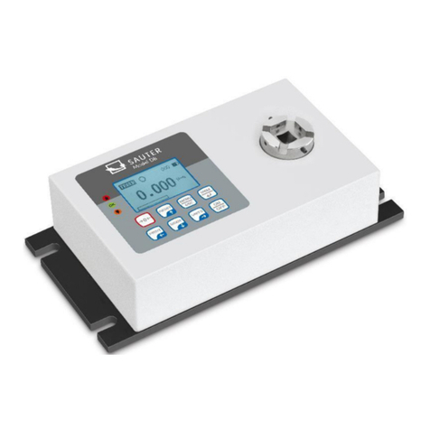
sauter DA User manual

Sauter GmbH
Ziegelei 1
D-72336 Balingen
e-mail: info@kern-sohn.com
Phone: +49-[0]7433- 9933-0
Fax: +49-[0]7433-9933-149
Internet: www.sauter.eu
Instruction manual digital torque tester
SAUTER DA
Version 2.0
03/2020
GB
DA-BA-e-2020
PROFESSIONAL MEASURING

2 DA-BA-e-2020
GB
SAUTER DA
V. 2.0 03/2020
Instruction manual digital torque tester
Thank you for purchasing the digital torque measuring device from SAUTER. We hope
that you will be very satisfied with the high quality of the hardness tester and its
extensive functionality. Although the device is a complex and technically advanced
measuring instrument, it is designed for many years of trouble-free use, provided that
it is used for its intended purpose and properly maintained. Before using the instrument
for the first time, please read this operating manual carefully and ensure that it is
always kept within easy reach during use. For any questions, requests and
suggestions, please contact our customer service department at the telephone number
provided.
Table of contents:
1Before commissioning.................................................................................. 3
2General operating information ..................................................................... 3
3Initial commissioning.................................................................................... 3
4Weight and dimensions................................................................................. 3
5Technical data................................................................................................ 4
6Operation of the torque measuring instrument DA .................................... 5
6.1 Before commissioning............................................................................................................. 5
6.2 Switching on the device........................................................................................................... 5
6.3 Basic functions of the device.................................................................................................. 5
6.4 Main menu................................................................................................................................. 9
6.5 Measurement methods .......................................................................................................... 14
7Control buttons............................................................................................ 15
8Conversion factoren.................................................................................... 16

DA-BA-e-2020 3
1 Before commissioning
Before putting the device into operation, check the delivery for any transport damage
to the packaging, the plastic case and the device itself. Should this be the case,
SAUTER must be contacted immediately.
2 General operating information
Functions of the digital torque measuring instrument that are used most frequently (i.e.
display of the torque value, peak hold function, zeroing and changing the displayed
unit) can be called up by pressing a corresponding button on the front panel (see
paragraph Basic functions of the measuring instrument). The setting of the measuring
instrument is done with the menu key (see paragraph Main menu).
3 Initial commissioning
The SAUTER DA digital torque measuring instrument is equipped with a battery set
consisting of 4 rechargeable NiMH AAA batteries. To be on the safe side, the
rechargeable batteries are completely discharged for transport and separated from the
power supply. Insert batteries before using the unit for the first time. To achieve
maximum battery life, recharge the batteries for at least 14-16 hours using the mains
adapter supplied.
4 Weight and dimensions
Torque tester
DA 1-4
DA 5-3
DA 10-3
Dimension
(LxWxH)
250x160x60
250x160x100
Weight
3kg
Packaging
Plastic case

4 DA-BA-e-2020
5 Technical data
Torque tester
DA 1-4
DA 5-3
DA 10-3
Maximum torque
1 Nm
5 Nm
10 Nm
Usable measuring range
5-100% of FS (Full Scale)
Accuracy
(Composite error)
±0.5% of full scale range
Creep
±0.002 of full scale range
Non-linearity
±0.002 of full scale range
zero load variation in
temperature
±0.002 of full scale range/°C
Nominal voltage
220V 50/60Hz
Backup
3A
Operating temperature
20±10°C
Storage and transport
temp.
-15°C up to 65°C
Relative air humidity
Not more than 70
Min/Max diameter of the
test object
10mm/165mm

DA-BA-e-2020 5
6 Operation of the torque measuring instrument DA
6.1 Before commissioning
Insert the four rubberised bottle holders into the openings provided for this purpose,
adjusting their arrangement to the diameter of the bottle or glass. Ensure that the
rubberised bottle holders are inserted as far as they will go and that they are locked on
the keyway. The rubberised holders must not twist after the test sample has been
inserted. The rubber coating ensures a better adhesion of the inserted test sample,
e.g. a bottle, to the measuring instrument. It must be ensured that the measuring plate
is neither loaded nor exposed to the action of any other force when the instrument is
switched on.
6.2 Switching on the device
There are 8 keys arranged on the control panel.
To switch on the device, press the ON/OFF button. A brief autotest will then be
performed, during which the display will show the permissible load value in Newtons.
As soon as the autotest is performed, zero values are displayed, provided that the
measuring plate is unloaded. This is because the meter is automatically zeroed during
the autotest procedure.
Please do not overload the load sensor! Risk of irreparable damage! If the torque
value exceeds 120% of the full scale range, an acoustic signal is triggered and the
symbol OL (eng. overload) appears on the display. If this is the case, remove the test
load and then press the RESET key.
Pressing the ON/OFF key switches the unit off.
When switching off, all current settings are saved, so that the same operating mode is
selected when switching on again.
6.3 Basic functions of the device
The torque gauge can display the torque value for both clockwise (clock-wise, CW,
symbol: ) and counter-clockwise (CCW, symbol: ) operation.

6 DA-BA-e-2020
CW torque value display function
Symbol
of the clockwise rotation
Load indicator beam
of the clockwise rotation
Display function of the CCW torque value
Symbol
of the turning process against
clockwise
Load indicator beam
of the counterclockwise rotation
The load indicator bar of the rotation is used to display the load to which the load sensor
is exposed.
When turning clockwise (CW), the load indicator bar moves from right to left. When
turning counterclockwise (CCW), the load indicator bar moves from left to right.
Zeroing the display
During operation it is often necessary to zero the display so that the values already
displayed are not taken into account in the next measurement. To do this, press and
then release the ZERO button.
Changing the measuring unit
Depending on the permissible load of the measuring instrument used, the following
measuring units are available: N-m, kgf-cm, kgf-m, in-lbf, ft-lbf.
To change the measuring unit, press the UNITS key. Each time this key is pressed
again, another measuring unit is displayed until the originally set measuring unit is
displayed. During the selection process, the measurement results are automatically
converted.
Important! It must be remembered that not all units of measurement are always
available. This depends on the permissible load of the respective instrument.

DA-BA-e-2020 7
Changing the measuring mode
The following measuring functions are available: Track, First Peak-Torque and Peak-
Torque.
The measuring function is changed by pressing the MODE button. Pressing this key
again selects the following measuring function until the originally set function is
displayed.
Track function
Press and hold the MODE button until the displayshows the name of the measurement
function "Track". The torque value for the rotation detected by the load sensor is
displayed. The measurement results are displayed continuously:
Symbol of the track function
first peak torque function
Press and hold the MODE key until the display shows the designation of the measuring
function "F-Peak". The first torque peak value is displayed:
Symbol of the
First Peak Torque Function
Peak torque function
Press and hold the MODE key until the display shows the name of the measurement
function "Peak". The highest measured torque value is displayed:
Symbol of the
Peak torque function
Resetting the device
Stored peak values of both types are deleted with the RESET button. This also enables
the acquisition of further peak values.

8 DA-BA-e-2020
Display backlight
By pressing any key, the backlight of the display switches on for 60s. The same applies
if the torque value detected by the load sensor will be higher than 0.5% of the full scale
range.
Saving measured values
Measured values can be saved at any time. To do this, press the MEM/ENTER key.
The memory capacity allows you to store up to 500 measurement results, including
measurement units.
Output signal
The measurement result obtained can be transferred to the PC. It is done by pressing
the PRINT key or by interrogating the instrument from the PC. The respective
command can be sent via RS232 or USB.

DA-BA-e-2020 9
6.4 Main menu
Pressing the MENU/ESC key calls up the "Main Menu" screen. The arrow keys UP or
DOWN are used to select desired positions in the mask. Pressing the ENTER key
selects the desired sub-menu, then calls up the desired function and then enters the
respective value. The arrow keys UP, DOWN, LEFT and RIGHT are also used to
change numerical values. Pressing the ESC key returns to the main menu screen.
MAIN MENU
1) AUTO-OFF
2) PASS-FAIL
3) MEMORY
4) CALIBRATION
5) DIAGNOSTIC
6) ABOUT
AUTO-OFF (AUTOMATIC SWITCH-OFF)
Press the MENU key. The main menu mask appears on the display. Use the UP or
DOWN arrow keys to position the cursor on the AUTO-OFF function. Press the ENTER
key. The AUTO-OFF menu mask appears on the display. Press the ESC key to return
to the main menu screen.
The AUTO-OFF function helps to extend the battery life. It can be used to set the time
after which the device should be switched off after the last operating activity (setting
values: Off, 5, 10 and 15 min). If this function is activated, the symbol AO appears in
the main menu mask.
AUTO-OFF MENU
1) OFF
2) 5 MINUTE
3) 10 MINUTE
4) 15 MINUTE
Use the UP or DOWN arrow keys to position the cursor accordingly. Then press
ENTER to select the AUTO-OFF function and return to the main menu screen.
MAIN MENU
1) AUTOMATIC SWITCH-OFF
2) PASS-FAIL
3) MEMORY
4) CALIBRATION
5) DIAGNOSIS FUNCTION
6) DEVICE INFO

10 DA-BA-e-2020
PASS-FAIL
This function is used to set the permissible torque range.Thus, the upper and the lower
limit value of the torque range are determined. If the torque value falls within the
defined range, the displayshows the message PASS (OK). If the torque value detected
is outside the specified range (above or below the range), the display shows FAIL
(NOK). When the PASS-FAIL function is active, the display shows the symbol.
To call up the PASS-FAIL menu screen, position the cursor on the PASS-FAIL function
using the UP or DOWN arrow keys, then press the ENTER key. The display shows the
PASS-FAIL function screen. Press the ESC key to return to the main menu screen.
PASS FAIL MENU
UPPER = 2. 5 N.m
LOWER = 1.0 N.m
Press 'Zero' key to
Clear both values.
Use the LEFT arrow key to position the cursor on the selected value. Set the desired
value with the UP or DOWN arrow keys. Press and hold the key to scroll the list. Select
the desired measuring unit with the RIGHT key. Press the ENTER key to save the
setting made and return to the main menu screen.
The PASS-FAIL function is automatically turned off when the setting of the lower limit
(LOWER) and upper limit (UPPER) is 0 N.
The LOWER value must be lower than the UPPER value.
PASS FAIL MENU
UPPER LIMIT = 2. 5 N.m
LOWER LIMIT = 1.0 N.m
Press the 'Zero' key,
to delete both values.

DA-BA-e-2020 11
Example 1 LOWER LIMIT= 0 N-m, UPPER LIMIT= 20 N-m
Load
The "UPPER" LED is on. Other LEDs are off.
Upper limit
The "OK" LED is on. Other LEDs are off
Time
Figure 6b
Example 2 LOWER LIMIT= 20 N-m, UPPER LIMIT= 0 N-m
Load
The "OK" LED is on. Other LEDs are off.
Lower limit
The "LOWER" LED wants ON. Other LEDs are off.
Time
Figure 6b
Example 3 LOWER LIMIT= 10 N-m, UPPER LIMIT= 20 N-m
Load
The "UPPER" LED is on. Other LEDs are off.
Upper limit
The "OK" LED is on. Other LEDs are off.
Lower limit
The "LOWER" LED is on. Other LEDs are off.
Time
Figure 6c

12 DA-BA-e-2020
MEMORY (MEMORY)
This function is used to view stored data records, to delete current data records, to
delete all data records and to print data stored in these data records.
To access the MEMORY menu mask, first call up the main menu mask. Then use the
UP or DOWN arrow keys to move the cursor to the MEMORY position and then press
ENTER. The display shows the memory mask. To return to the main menu screen,
press the ESC key.
Press the arrow keys UP or DOWN to change the memory mask. Press and hold the
key to scroll to the position for changing the memory mask. Pressing the PRINT key
controls the print output of stored data and data transmitted via serial port. To access
the DELETE menu screen, press the ZERO key.
DELETE?
1) NO
2) DELETE
3) DELETE ALL
Select the desired delete option with the UP or DOWN arrow keys. If the NO option is
selected and then the ENTER key is pressed, the system returns to the memory mask.
If the DELETE option is selected and the ENTER key is pressed, the current stored
results are deleted and the memory mask is returned to. Selecting the DELETE ALL
option and pressing ENTER will delete all stored results and return to the memory
mask.

DA-BA-e-2020 13
CALIBRATION (CALIBRATION)
Calibration of the measuring instrument is carried out by the manufacturer's service
personnel. Detailed information in this regard can be obtained from SAUTER's dealer
or directly from the manufacturer.
DIAGNOSTIC (DIAGNOSTIC FUNCTION)
This function is used to check the status of the load cell. If there are indications that
the load cell transformer has been overloaded, it is possible to check the state of the
load cell directly.
To do this, place the measuring instrument horizontally on a level, horizontal surface
and call up the main menu screen. Select the DIAGNOSTIC function with the UP or
DOWN arrow keys and press ENTER. The "Diagnostic" menu mask appears on the
display. To return to the main menu screen, press the ESC key.
DIAGNOSTIC
OVERLOAD COUNT: 2
Total overload measurement
ORG. OFFSET : +0.4 %
Offset value from the last calibration (%)
CUR. OFFSET : +0.4 %
Current offset value (%)
If the offset value is in the range of 5% to 10%, contact the instrument supplier to have
a new calibration performed.
If the offset value exceeds 10%, contact the device supplier to have the load cell
replaced.
The values given are only approximate values. Calibration/repair of the instrument can
be caused by various circumstances. This is due to device-specific parameters of the
load cell.

14 DA-BA-e-2020
ABOUT (DEVICE INFO)
This function is used to display device-related information (firmware version, model,
permissible load, serial number). To enter the ABOUT menu screen, first call up the
main menu screen, then position the cursor on the ABOUT function using the UP or
DOWN arrow keys, and then press ENTER. The display shows the About menu
screen. To return to the main menu screen, press the ESC key.
ABOUT
FIRMWARE REV. : 3.0
MODEL: DA
CAPACITY: 10 N.m
S/N: 05130001
6.5 Measurement methods
In order to achieve higher accuracy of measurements, the torque ratio must
correspond to the value specified for the respective device. The bending and torque
loads acting on the load cell must be reduced, as they can affect the measurement
result.
The permissible load according to the specifications on the front of the device must not
be exceeded under any circumstances. Otherwise the load cell will be permanently
damaged, even in the event of a short-term overload. Such damage is excluded from
the warranty.

DA-BA-e-2020 15
7 Control buttons
MENU/ESC:
•Opens the menu window with the individual submenus
•By pressing the MENU/ESC button in the menu, you can return to the previous
page
ZERO (zeroing):
•Zeroing the display in track mode (tare function)
ENTER:
•Confirm the selection in the menu
•Saving a measured value in PEAK mode
PRINT (print function):
•Output of the memory contents to PC or printer
RESET (delete function):
•Delete the current PEAK value
UNIT (units of measurement):
•Press the key briefly: Switch between N, gf, kgf, ozf, lbf, mN
Mode (mode change):
Assignment with three functions:
•Track mode (continuous measurement)
•Peak Mode Train
•Peak Mode Print
ON / OFF:
•On / Off button (press button for approx. 1 s)

16 DA-BA-e-2020
8 Conversion factoren
Unit
n.m.
p.cm.
plc
Calo-
funt
Stopo-
funt
N. m
1
10,197
0,10197
8,8507
0,73756
p.cm.
0,0980665
1
0,01
0,86796
0,07233
plc
9,80665
100
1
86,796
7,233
calofunt
0,11298
1,152
0,01152
1
0,08333
stopofunt
1,3558
13,8255
0,138255
12
1
Table of contents
Other sauter Test Equipment manuals

sauter
sauter HD User manual

sauter
sauter SAUTER HMO User manual

sauter
sauter TVL User manual

sauter
sauter SD Series User manual

sauter
sauter SAUTER HMO User manual

sauter
sauter TVO 500N300 User manual

sauter
sauter HK-D User manual

sauter
sauter HMM User manual

sauter
sauter TVL User manual

sauter
sauter HMM User manual

sauter
sauter SD 50N100 User manual

sauter
sauter TB-US User manual
sauter
sauter HO Series User manual

sauter
sauter HMP User manual

sauter
sauter HK-D User manual

sauter
sauter TVO-N User manual

sauter
sauter TE 1250-0.1 FN User manual

sauter
sauter SAUTER HMO User manual

sauter
sauter SD Series User manual

sauter
sauter HN-D User manual