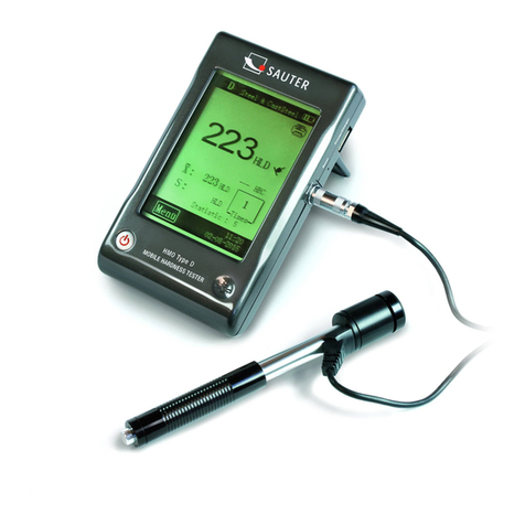
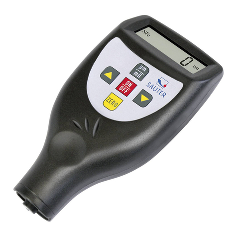
sauter SAUTER HMO User manual

Sauter GmbH
Ziegelei 1
D-72336 Balingen
e-mail: info@kern-sohn.com
Phone : +49-[0]7433- 9933-0
Fax: +49-[0]7433-9933-149
Internet: www.sauter.eu
Instruction manual mobile Leeb
hardness tester
SAUTER HMO
Version 2.0
04/2020
GB
HMO-BA-e-2020
PROFESSIONAL MEASURING

2 HMO-BA-e-2020
GB
SAUTER HMO
V. 2.0 04/2020
Instruction manual mobile Leeb hardness tester
Thank you for purchasing the mobile digital Leeb impact hardness tester from
SAUTER. We hope that you will be very satisfied with the high quality of this device
and its extensive functionality. For any questions, wishes and suggestions we are at
your disposal.
Table of contents:
1Before commissioning.................................................................................. 3
2Introduction.................................................................................................... 3
2.1 Measuring principle.................................................................................................................. 3
2.2 Structure.................................................................................................................................... 4
2.3 Technical data........................................................................................................................... 5
2.4 Area of application ................................................................................................................... 5
3Test procedure............................................................................................... 6
3.1 Preparation of the device ........................................................................................................ 6
3.2 Preparation of the sample ....................................................................................................... 6
3.3 Test execution .......................................................................................................................... 8
3.4 Browsing ................................................................................................................................... 8
3.5 Print............................................................................................................................................ 9
4Setup............................................................................................................... 9
4.1 Settings in the main mask....................................................................................................... 9
4.2 Menu settings ......................................................................................................................... 10
5Care and maintenance................................................................................. 14
5.1 Periodic maintenance ............................................................................................................ 14
5.2 Store......................................................................................................................................... 14
5.3 Calibration............................................................................................................................... 15
6Annex............................................................................................................ 16
6.1 Conversion area ..................................................................................................................... 17
6.2 Scope of delivery.................................................................................................................... 17

HMO-BA-e-2020 3
1 Before commissioning
Before putting the device into operation, check the delivery for any transport damage
to the packaging, the plastic case and the device itself. Should this be the case,
SAUTER must be contacted immediately.
2 Introduction
2.1 Measuring principle
The measuring principle for the measurements carried out with this dynamic impact
hardness tester is physically quite uncomplicated. An impact body with a hard metal
tip is hurled against the surface of the test object by the spring force. When the impact
body hits the surface, it can be damaged, which ultimately leads to a loss of kinetic
energy.
This energy loss is calculated on the basis of velocity measurements, at a certain point
in time when the impactor is at a certain distance from the surface, both in the rebound
and impact phases.
The fixed magnet in the impact body generates an induction voltage in the simple wire
coil of the impact tester. The voltage of the signal is proportional to the speed of the
impact body. The signal is processed by the electronics so that the hardness value can
be read on the display and then stored.
English
German
Impact phase
Impact phase
Rebound phase
Rebound phase
Time
Time

4 HMO-BA-e-2020
2.2 Structure
Display
Impact device (type D)
The display can be connected to almost any type ofLeeb rebound sensor. The rebound
sensor is detected automatically.
Take the rebound sensor type D (standard sensor). The description of other types can
be found in the appendix (chapter 5).
Display
The rebound hardness tester is equipped with a large LCD touch display.
1. Rebound sensor type: automatically detected or manually adjusted
2. materials: Material from which the sample is made
3. Battery indicator
4. Tolerance value
5. Conversion value
IMPORTANT: if this symbol is displayed "---", it means that the conversion is
out of range
6. Impact direction
1. impact body
2. support ring
3. bobbin
4. cable
5. pawl clamping device
6. loading pipe
7. release button
1. impact device socket 2. LCD display 3. mini-
USB socket 4. charging socket 5.ON-OFF button
3
4
1
2
5
Impact device Type
Material
Hardness value
Battery indicator
Impact direction
Conversion value
Impact counter
Time / Date
Lighting
Menu button
Statistics:
mean
value and
range
Tolerance
alarm

HMO-BA-e-2020 5
7. Hardness value: measured hardness value L (Leeb)
8. Statistical values: X: Average value S: Range
9. Statistical data: Number of strokes in statistical data
10.Impact counter: number of impacts performed
11.Lighting: Switching on and off by touch
12.Menu: Fade in and out of the setting mask by touch
13.Date / Time: the display of real time and date
2.3 Technical data
▪Display range HL: 0~999HLD
▪accuracy: ±6 HL
▪Display: large LCD display, illumination,
Touch display
▪Internal data memory: 500 measured values
▪Resolution: 1 (for HL, HV, HB, HSD, MPa); 0,1 (for
HRC, HRB)
▪Battery: rechargeable Li-Ion
▪Operating temperature: 0°C~+50°C (32°F~122°F)
▪Storage temperature: -10°C~+60°C (14°F~140°F)
▪Dimensions: 130 x 87 x 28 mm
▪Weight: 240g
2.4 Scope of application
•Suitable for all metals, ideal for testing production quality
•Optimally suited for testing heavy, large or already installed parts
•Suitable for carrying out measurements in places that are difficult to access
•Automatic adjustment of the impact direction
•Optimal tool for selective testing and acceptance control
•Simple operation and high measuring accuracy for measurements on round
surfaces (R > 10 mm)
•Metal production and processing, automotive industry and transport,
engineering and power plants, refineries, petrochemical industry, aerospace
industry, shipbuilding industry, metal construction, test and laboratory services

6 HMO-BA-e-2020
3 Test procedure
3.1 Preparation of the device
Connect
Connect the display with the impact device with the signal cable.
Charge battery
Charge the device before first use.
Switch on
Switch on the device by pressing the button.
Calibration
Before using the test block for the first time, calibrate the instrument (see 4.3
"Calibration")
3.2 Preparation of the sample
Unsuitable material samples can cause measuring errors. Therefore, test preparation
and execution should be carried out according to the sample properties. The
preparation of the sample and its surface should meet these basic requirements:
During the surface preparation of the sample, its surface should not be exposed to
thermal cooling or heating.
The test surface should be flat and have a metallic gloss. There must be no oxide
layers or other contamination.
Signal cable
Figure 2-1

HMO-BA-e-2020 7
Roughness of the test surface
The sample should have sufficient mass and stiffness. If not, the impact may cause a
displacement or movement, which may lead to a significant measurement error.
As a general rule, if the weight of the sample is 5 kg or more, testing can be performed
directly.
Sample thickness
The thickness of the sample as well as the thickness of the homogeneous layer (or the
hardening layer of the surface) should have a sufficient material thickness.
If the sample surface is not flat, the radius of the test area should not be less than 30
mm (50 mm for type G). If it is not specified, an appropriate support ring should be
used.
The sample should have no magnetic properties.
English
German
Direct measurement
Direct measurement
Clamping
measurement
Clamp measurement
Coupling
measurement
Coupling
measurement

8 HMO-BA-e-2020
3.3 Test execution
Shop
Load the impact device by pushing the
loading tube forward.
Positioning
Then position the impact device and hold it
on the surface of the sample at the desired
measuring point. The direction of impact
shall be perpendicular to the surface of the
sample.
Impact (measurement)
Perform the measurement by pressing the release button. The measured hardness
value is displayed immediately.
Reading test results
Read the measurement result of the test from the display.
Note:
Normally, 5 individual measurements are made at each measuringpoint of the sample.
The value range (difference of the maximum and minimum value) should be less than
15 HL. The distance between any two measuring points should be ≥ 3mm; the distance
between the point of impact and the edge of the sample should be ≥ 3mm.
3.4 Browse
The hardness tester enables hardness values to be stored, which can then be
searched after the measurement has been completed. To do this, enter the menu to
select the desired browse mode (see par. 3.2.3 for detailed information).
English
German
Loading
Shop
Locating
Positioning
Impacting
Impact
Loading Locating
Impacting
Figure 2-7

HMO-BA-e-2020 9
3.5 Print
The hardness tester can be connected to a wireless printer to
print a test report.
Place the printer near the tester (at a distance of up to 2 m)
and switch it on.
A test report is shown in Fig. 2-7. Detailed report
information can be defined in the respective menu (see par.
3.2.2)
Fig. 2-6
English
German
Set type of impact device
Setting the type of impact device
Set material
Set material
Set limit value
Set limit value
Set impact direction
Setting the impact direction
Turn on/off backlight
Lighting ON / OFF
Enter menus
Call up the menu
4 Setup
The hardness tester is equipped with a touch display and most settings can be made
directly from the main screen. Some functions require calling up the respective menu
masks to make the desired settings or for operating purposes.
4.1 Settings in the main mask
The hardness tester is equipped with a touch display and the most common test
parameters can be set directly in the main mask (Fig. 3-1).

10 HMO-BA-e-2020
4.2 Menu settings
To call up the desired menu masks, the menu in the main mask must be activated.
In the respective menu:
Press the "△" or "▽" button to scroll up or down the page
press the Back key in the upper menu or return to the main screen.
Test settings
Material group
The "Material group" function allows you to select materials to be tested. It only
determines the conversion to other hardness scales. If only the Leeb hardness value
is required, it can be disregarded.
If the material is not specified in the menu, the user must familiarise himself with the
operating instructions in order to select a comparable type of material.
Impact direction
Test
setting
Material group
System
settings
Fabric Settings
Impact direction
Automatic printing ON/OFF
Scale
Gross error ON/OFF
Limit values
Key tone ON/OFF
Statistics
Alarm ON/OFF
Workpiece
Language: EN
Pressure
setting
Positions
Date / Time
Printing the memory
contents
Lighting duration
Print all
Calibration
Test calibration
Memory
Search all
Touch Calibration
Browse Selected
Information
upload data
Delete selected
ones
Delete All
Fig. 3-2
→ →
Fig. 3-3

HMO-BA-e-2020 11
Scale
HB - Brinell hardness
HRB - Scale B Rockwell
HRC - Scale C Rockwell
HV - Hardness according to Vickers
MPa - tensile strength
no conversion
Comments:
❶Because different hardness scales can have different ranges, it is sometimes not
possible to make a conversion. If this is the case, the symbol "---" is displayed.
❷The set material group must be reset if the tensile strength (MPa) is selected.
❸As is generally known, the conversion is for reference purposes only. Comparative
tests are required to ensure an accurate conversion.
Limit values
The max. limit value and the min. tolerance value are
adjustable. If the measured hardness values are
outside the range, the display immediately triggers a
sound alarm.
The minimum and maximum limit values can be set
using a digital keypad (Fig. 3-6).
To select a different position or digit, press the or
key.
Statistics
The device is equipped with an automatic statistics
function. It allows you to set statistical parameters to
determine the average ( ) and range value (S).
Important:
❶The value range for statistical parameters is 1 ~
99, whereby with the setting "1" no statistical
processes are carried out by the system.
❷If some items (material group etc.) are reset, the
count starts from "0".
Figure 3-7
Fig. 3-8
Fig. 3-5
Fig. 3-6
Fig. 3-4

12 HMO-BA-e-2020
6) Work piece
Grouping of test elements for the purpose of request,
printing or data processing.
The range is 1-50 and can be saved.
Print settings
Position Select the position of the print
report from the test.
Print memory contents Here you can
select the range of data to be printed.
Print all It is possible to printall measured
values from the internal memory.
Memory management
It is possible to browse data in the memory as
well as delete data from the memory.
The stored test data includes all test
information. Up to 500 data sets can be
stored. If the memory is full, the oldest data is
overwritten by the new data.
Therefore, it is recommended to save data in
a different way (e.g. printing or uploading to
PC) from time to time to prevent accidental
data loss.
Browse
The unit has three browse modes:
Search from A to Z, Search from Z to A
and browsing selected items.
Press the or key to move the page up/down.
to scroll down.
Press the key to delete a selected data group.
Press the key to print a selected data group.
Press the OK key to display -
the test time of the selected data group.
Figure 3-10
Fig. 3-12
Fig. 3-13
Fig. 3-14
→
Fig. 3-9
Fig. 3-9
→→
Fig. 3-11

HMO-BA-e-2020 13
Delete
It is possible to delete larger amounts of data or all data at once from the memory.
It is recommended to delete the data individually.
IMPORTANT: Deleted data cannot be recovered. Therefore, it is recommended to use
the delete function with care.
Fig. 3-16
3) Upload data
The data from the memory can be transferred to the PC
can be uploaded.
To do this, connect the PC and start the upload software
call (Ehard).
Select the Upload Data function, then the data can be received or processed in the
software by PC.
Detailed information can be found in the operating instructions for the software.
System settings
Material settings
It is possible to adapt conversion tables as
required and to select them for material "A", "B"
and "C".
It is possible to select a scale as required and
enter data in the conversion table (Fig. 3-19)
Automatic printing
If the "Automatic printing" function is active
(ON), a test report is printed automatically after
the test of the respective statistics group is
completed (the printer must be switched on).
Coarse error
If the function "Gross error" is active (ON), gross errors are displayed according to
the settings for Grubbs after the determination of "Statistical parameters".
Fig. 3-15
→
Fig. 3-16
Fig. 3-18
Fig. 3-17
Fig. 3-19

14 HMO-BA-e-2020
5 Care and maintenance
5.1 Periodic maintenance
General information
Avoid shocks. After use, place the device back into the transport case.
The rebound sensor must be stored in a triggered state.
Avoid use in a strong magnetic field. Protect all components from any contact with
grease or oil.
Clean impact device
In principle, the tube and the housing of the impact device must be cleaned every 1 to
2 thousand measurements.
Replacement of the impact ball
Continuous use may damage the impact ball. It shall be replaced as soon as its
condition appears to affect the accuracy of the measurement.
5.2 Shop
Fig. 4-2

HMO-BA-e-2020 15
5.3 Calibration
Test Calibration
The method is used to calibrate the
instrument to reduce the extent of the
error in the future.
To do this, select the "Test calibration"
function. Select the type of impact device.
Then select the scale on which the
calibration is to be carried out.
If HL is selected, the calibration mask can
be selected directly.
If a different scale is selected, select the fabric type for the test piece that is used by
default.
Perform 5 effective measurements on the test block (if the alarm function is active (ON)
and the number of strokes is less than 5, press the OK key; a query is made as to
whether operating errors should be displayed), measured values are displayed (it is
possible to delete incorrect values and return).
Touch calibration
This procedure is used to calibrate the
correspondence between the sensor of the
touch display and the display parameters.
If there are deviations between the actual
position of press contacts of the touch display
and the actuating position of displayed values,
a touch calibration must be carried out.
To do this, simply press the centre of the
crossing line or the square frame according to
the displayed note.
Fig. 4-3
Fig. 4-1
Fig. 4-4

16 HMO-BA-e-2020
6 Annex
Impact device type A-1
Type D+15 Type G
Heavy housings and solid forgings.
Type DL Type C
Surface hardened component,
layers, thin walls or impact sensitive
component
Suitable for use in particularly limited
spaces or at the base of grooves / slots.
Standard type, suitable for
practically all applications.
Type D Type DC
Shortened D-variant, possibility of
carrying out measurements in
tighter places.
Especially thin front part, measuring coil with
feedback. Suitable for hardness testing on
grooves/grooves and on surfaces with
indentations.

HMO-BA-e-2020 17
6.1 Conversion area
English
German
Type
Type
Material
Material
Steel
Steel
Cast steel
Cast steel
Alloy tool steel
Tool Steel Alloy
Grey cast iron
Grey cast iron
Ductile iron
Ductile cast iron
cast al alloy
Aluminium casting alloy
Brass
Brass
Bronze
Bronze
Copper
Copper
Forging steel
Forged steel
6.2 Scope of delivery
1. Display
2. Impact device
3. Test block
4. Mini Printer
5. Battery charger
6. Small support ring,
Cleaning brush
7. Operating instructions
8. Transport case
Note:
To view the CE declaration, please click on the following link:
https://www.kern-sohn.com/shop/de/DOWNLOADS/
Other manuals for SAUTER HMO
2
Table of contents
Other sauter Test Equipment manuals

sauter
sauter SD Series User manual

sauter
sauter TN-EE User manual

sauter
sauter HN-D User manual

sauter
sauter TVP User manual

sauter
sauter TVL-XL User manual

sauter
sauter TVO-N User manual

sauter
sauter HMM User manual

sauter
sauter HN-D User manual

sauter
sauter SD 50N100 User manual

sauter
sauter SAUTER HMO User manual