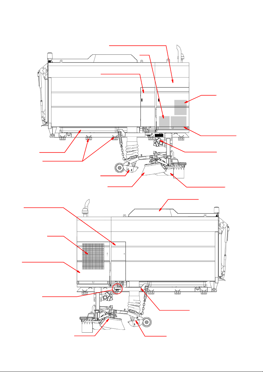
SCARAB M6 SWEEPER KIT
Amdt.1 - 03 November 2009 Operator’s Manual 2
TABLE OF CONTENTS
Para Title Page
GENERAL INFORMATION ................................................................................................. 1
TABLE OF CONTENTS (This Page).................................................................................... 2
HEALTH AND SAFETY ADVICE.......................................................................................... 3
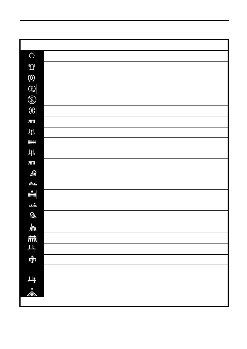
SWITCH SYMBOLS ............................................................................................................. 4
LCD SCREEN INFORMATION ........................................................................................... 5
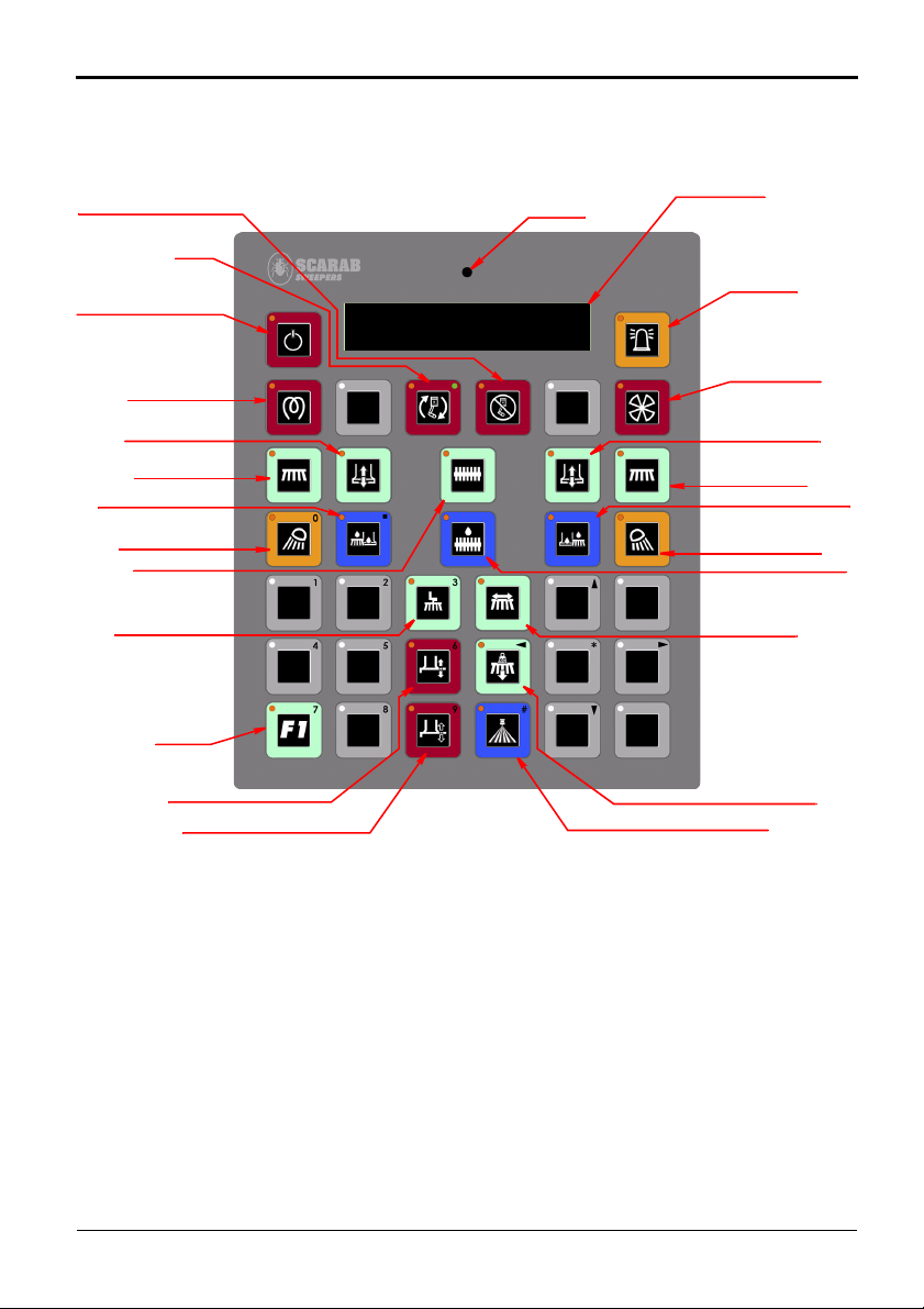
DESCRIPTION OF SWEEPING CONTROLS ....................................................................... 6
The CANbus System................................................................................................... 6
Main Panel Switch Descriptions ............................................................................ 7
Additional Controls & Instruments....................................................................... 12
OPERATING IN SWEEP MODE........................................................................................ 12
Starting the Auxiliary Engine ................................................................................... 12
Activating the Control Panel.................................................................................. 13
Sweeping.................................................................................................................. 13
Reverting to Normal-Drive Mode........................................................................... 13
DISCHARGING THE HOPPER (TIPPING)......................................................................... 15
USING THE AUXILIARY HYDRAULIC PUMP..................................................................... 16
THE REAR-MOUNTED WANDER BOOM......................................................................... 17
USING THE LOW-PRESSURE WATER PUMP..................................................................... 18
Lubrication................................................................................................................ 18
Draining..................................................................................................................... 20
USING THE OPTIONAL HIGH-PRESSURE WATER PUMP ................................................. 19
Oil Level .................................................................................................................... 20
Draining..................................................................................................................... 20
Priming ...................................................................................................................... 20
RECOMMENDED OPERATOR’S ROUTINE MAINTENANCE........................................... 21
KEY MAINTENANCE PROCEDURES ............................................................................... 23
Auxiliary Engine ........................................................................................................ 23
Cleaning the Suction Fan & Screens ..................................................................... 24
Suction Nozzle Clearances..................................................................................... 25
Side Brushes & Skirts ................................................................................................. 25
Manual Greasing ..................................................................................................... 26
Recommended Lubricants & Consumables ........................................................ 27
Other Fluid Levels..................................................................................................... 27
ABOUT THE M6 HYDRAULIC DRIVE SYSTEM .................................................................. 28
LEGIONELLA STATEMENT................................................................................................ 29