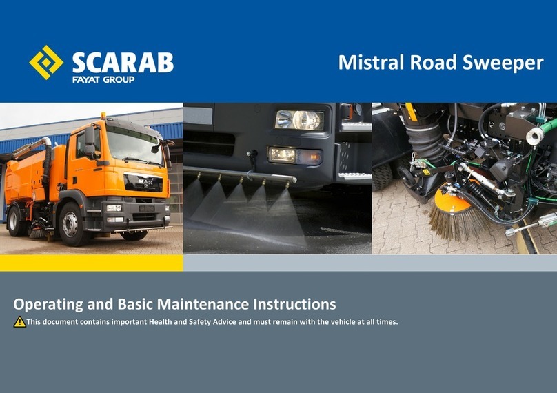
Scarab Magnum User manual


MAIN FEATURES OF A TYPICAL SCARAB SWEEPER
LEFT HAND
SUCTION NOZZLE
SERIAL NUMBER
PLATE LOCATION
LEFT HAND
SIDE BRUSH
SIDE LOADING
HATCH
HOPPER COVER
MAIN HYDRAULIC VALVES
PNEUMATIC VALVES
OIL TANK & COOLER
EXHAUST GANTRY
WATER TANK
LOCKER
RIGHT HAND
SUCTION NOZZLE
RIGHT HAND
SIDE BRUSH
WIDE SWEEP BRUSH
WANDER
HOSE
SIDE
LOADING
HATCH
DOOR
RAM
L-P WATER PUMP
Scarab Merlin
Scarab Magnum
AUXILIARY HAND PUMP
EXTERNAL HOPPER
SECOND HOPPER
RAISE BUTTON
(RHD ONLY)
& DOOR CONTROLS
FUEL TANK
ALWAYS ON NEARSIDE OF VEHICLE
& STRAINERS
WATER TANK LEVEL GAUGE
MOUNTED ON COOLER GANTRY
LOCKER
H-P FRONT
SPRAY BAR VALVE
ACCESS COVER WITH
OIL LEVEL APERTURE
FUEL TANK
DOOR LOCKING MECHANISM
& OPTIONAL FAN-WASH VALVE
ALWAYS ON NEARSIDE OF VEHICLE

OPERATOR’S MANUAL
HYDROSTATIC
TRUCK-MOUNTED
SWEEPERS
VEHICLES EQUIPPED WITH CANbus CONTROLS
When re-ordering this document, please quote the following Part Number:
Manual Z030376
Original Issue ..................... Dec. 2004
Amdt.1 ............................... Aug. 2005
This manual is published by the Technical Publications Department of Scarab Sweepers
Limited and every effort is made to ensure that the information it contains is correct at the
time of publication. Due to a policy of continuous development, however, the Company
reserves the right to alter the specification and to supply when so altered without
reference to illustrations and descriptions in this manual.
Scarab Sweepers Limited
Pattenden Lane, Marden, Kent TN12 9QD
Telephone: 01622 831006 Fax: 01622 832417
International: +44 1622 831006 International +44 1622 832417
e-mail: scarab@scarab sales.com Web site: www.scarab-sweepers.com
Publication Z030376 © Scarab Sweepers Limited 2005

SCARAB HYDROSTATIC TRUCK-MOUNTED SWEEPERS
1 Operator’s Manual Original Issue - 28 November 2006
GENERAL INFORMATION
WARNING - VOLTAGE SENSITIVE COMPONENTS
DO NOT USE A BOOST STARTER / SUPER START. IF BATTERIES ARE
NOT CHARGED ALWAYS USE A FRESH SET. A BOOSTED START WILL
BURN OUT THE VEHICLES ELECTRONIC CONTROL NODES.
WEIGHTS, DIMENSIONS AND CAPACITIES
Gross Vehicle Weight (GVW)
MERLIN . . . . . . . . . . . . . . . . . . . . . . . . . . . . . . . . . . . . . . . . . . . . . . . . . . . . . 7.5 tonne to 12.0 tonne
MAGNUM . . . . . . . . . . . . . . . . . . . . . . . . . . . . . . . . . . . . . . . . . . . . . . . . . 13.0 tonne to 15.0 tonne
Payload*
MERLIN . . . . . . . . . . . . . . . . . . . . . . . . . . . . . . . . . . . . . . . . . . . . . . . . . Typically 2300 kg to 6300 kg
MAGNUM . . . . . . . . . . . . . . . . . . . . . . . . . . . . . . . . . . . . . . . . . . . . . . Typically 6340 kg to 8540 kg
Overall Length*. . . . . . . . . . . . . . . . . . . . . . . . . . . . . . . . . . . . . . . . . . . . . . . . . . .Typically 5500 mm
Front Overhang*. . . . . . . . . . . . . . . . . . . . . . . . . . . . . . . . . . . . . . . . . . . . . . . . . .Typically 1240 mm
Rear Overhang* . . . . . . . . . . . . . . . . . . . . . . . . . . . . . . . . . . . . . . . . . . . . . . . . . .Typically 1350 mm
Wheelbase* . . . . . . . . . . . . . . . . . . . . . . . . . . . . . . . . . . . . . . . . . . . . . . . . . . . . .Typically 3000 mm
Overall Width*. . . . . . . . . . . . . . . . . . . . . . . . . . . . . . . . . . . . . . . . . . . . . . . . . . . .Typically 2220 mm
Overall Height (hopper lowered)* . . . . . . . . . . . . . . . . . . . . . . . . . . . . . . . . . . .Typically 2980 mm
Overall Height (hopper raised)* . . . . . . . . . . . . . . . . . . . . . . . . . . . . . . . . . . . . .Typically 4180 mm
Hopper Capacity
MERLIN . . . . . . . . . . . . . . . . . . . . . . . . . . . . . . . . . . . . . . . . . . . . . . . . . . . . . . . . . . . . . . . . . . . . 5.5 m3
MAGNUM . . . . . . . . . . . . . . . . . . . . . . . . . . . . . . . . . . . . . . . . . . . . . . . . . . . . . . . . . . . . . . . . . 7.5 m3
Fuel Tank Capacity*
MERLIN . . . . . . . . . . . . . . . . . . . . . . . . . . . . . . . . . . . . . . . . . . . . . . . . . . . . . . . . . . Typically 100 litres
MAGNUM . . . . . . . . . . . . . . . . . . . . . . . . . . . . . . . . . . . . . . . . . . . . . . . . . . . . . . . Typically 150 litres
Hydraulic Tank . . . . . . . . . . . . . . . . . . . . . . . . . . . . . . . . . . . . . . . . . . . . . . . . . . . . . . . . . . . . 15 litres
Water Tank*. . . . . . . . . . . . . . . . . . . . . . . . . . . . . . . . . . . . . . . . . . . . . . . . . . . 900 litres to 1800 litres
* Dependent upon chassis and specification
NOTE:
In view of the fact that many of the foregoing values are subject to variables such as
chassis type and machine specification, it is not possible to quote precise details. If this
type of information is required, Scarab recommend that you contact our Technical Sales
staff giving your sweeper’s Serial Number.
TOWING
SERIOUS DAMAGE TO THE TRANSMISSION WILL RESULT IF THE VEHICLE IS TOWED WHILE THE
HYDROSTATIC DRIVE IS ENGAGED.
If towing is necessary, it is imperative that the hydrostatic drive is disengaged before making
any attempt to tow the vehicle.
IDENTIFICATION PLATES
The SERIAL NUMBER PLATE is located on the rear face of the left hand suction nozzle spigot.
The Serial Number will comprise four numerical digits only (for example 5843).
For the location of the vehicle’s VIN PLATE and CHASSIS NUMBER, refer to the chassis
manufacturers’ documentation.
LIMITATIONS OF USE
The Scarab Merlin and Magnum are classified as truck-mounted heavy-duty suction road
sweeprs and, as such, are intended only for operation in the sweeping and associated roles
for which they have been expressly designed.
APPLICABILITY
This manual covers the operating requirements of the Scarab Merlin and Magnum
Hydrostatic sweepers with the CANbus system. For operating information on the Unidrive
range of CANbus sweepers, please refer to Manual No. Z031792. For non CANbus versions
please refer to publications Z027055 (Hydrostatic) and Z027054 (Unidrive).

SCARAB HYDROSTATIC TRUCK-MOUNTED SWEEPERS
Original Issue - 28 November 2006 Operator’s Manual 2
TABLE OF CONTENTS
Para Title Page
GENERAL INFORMATION ................................................................................................. 1
TABLE OF CONTENTS (This Page) .................................................................................... 2
HEALTH AND SAFETY ADVICE .......................................................................................... 3
EXPLANATION OF SWITCH OPERATING SYMBOLS ......................................................... 4
LCD Screeen Information ................................................................................................. 6
OPERATING ADVICE ........................................................................................................ 6
THE CANbus SYSTEM ........................................................................................................ 7
DESCRIPTION OF MAIN CONTROL PANEL ...................................................................... 8
DESCRIPTION OF AUXILIARY CONTROL PANEL ............................................................ 13
Rear-mounted Nozzle Option ........................................................................................ 15
Additional Controls and Instruments ............................................................................. 16
OPERATING MODES ....................................................................................................... 17
Engaging Hydrostatic Drive............................................................................................ 17
Suction Fan Boost-setting................................................................................................ 18
Climbing Gradients ......................................................................................................... 18
Selecting Normal-Drive Mode........................................................................................ 19
Reducing Noise Levels and Fuel Consumption............................................................ 19
DISCHARGING THE HOPPER (TIPPING) ......................................................................... 20
Operating the Rear Door................................................................................................ 20
Operating the Hopper .................................................................................................... 21
In-cab Controls...................................................................................................... 21
External Controls ................................................................................................... 22
USING THE AUXILIARY HYDRAULIC PUMP..................................................................... 23
Rear Door ......................................................................................................................... 23
Hopper.............................................................................................................................. 24
WANDER HOSE & WANDER BOOM................................................................................ 25
USING THE LOW-PRESSURE WATER PUMP...................................................................... 27
Draining............................................................................................................................. 27
USING THE OPTIONAL HIGH-PRESSURE WATER PUMP .................................................. 28
Oil Level / Draining / Priming .......................................................................................... 29
OPTIONAL SUCTION FAN WASH-ASSIST SYSTEM.......................................................... 29
RECOMMENDED OPERATOR’S ROUTINE MAINTENANCE............................................. 31
KEY MAINTENANCE PROCEDURES ................................................................................ 33
Cleaning the Suction Fan ............................................................................................... 33
Suction Nozzle Clearances............................................................................................. 34
Side Brushes & Skirts ......................................................................................................... 34
Draining & Cleaning the Water Strainers ...................................................................... 35
Manual Greasing............................................................................................................. 36
Recommended Lubricants & Consumables................................................................ 38
Fluid Levels........................................................................................................................ 38
SCARAB PARTS & SERVICE PROVIDERS......................................................................... 39
LEGIONELLA STATEMENT ................................................................................................ 40
ENGINE SPEED-CONTROLLER INSTRUCTIONS .....................................Inside Rear Cover

SCARAB HYDROSTATIC TRUCK-MOUNTED SWEEPERS
3 Operator’s Manual Original Issue - 28 November 2006
HEALTH & SAFETY ADVICE
THIS OPERATORS MANUAL CONTAINS ESSENTIAL INFORMATION AND MUST
REMAIN WITH THE VEHICLE AT ALL TIMES.
IN THE INTERESTS OF YOUR HEALTH AND SAFETY, IT IS IMPORTANT THAT
THE FOLLOWING POINTS ARE OBSERVED AT ALL TIMES:
• AT NO TIME SHOULD UNQUALIFIED PERSONNEL BE PERMITTED TO OPERATE OR
WORK ON THE SCARAB SWEEPER.
• BEFORE DRIVING THE VEHICLE ENSURE THAT ALL RELEVANT VEHICLE CHECKS
HAVE BEEN CARRIED OUT, THAT ALL EQUIPMENT IS STOWED AND THAT THE
BRUSHES HAVE BEEN RAISED.
• DO NOT OVERLOAD THE HOPPER.
• DO NOT DRIVE THE VEHICLE WITH THE HOPPER IN THE RAISED POSITION, EVEN IF
THE HOPPER IS EMPTY.
• ALWAYS USE THE SAFETY PROP TO SUPPORT A RAISED HOPPER. NEVER WORK
UNDER A RAISED CAB OR HOPPER UNLESS THE APROPRIATE PROP IS IN POSITION.
• BEFORE OPERATING EITHER THE HOPPER-TIP CONTROLS OR REAR DOOR, ENSURE
THAT THERE IS SUFFICIENT CLEARANCE AND THAT IT IS SAFE TO DO SO. ENSURE
THAT ALL PERSONNEL ARE CLEAR OF THE REAR DOOR.
• BEFORE WORKING ON THE MACHINE:
POSITION THE VEHICLE ON FIRM, LEVEL GROUND, APPLY THE HANDBRAKE, STOP
THE ENGINE, REMOVE THE IGNITION KEY.
• BEFORE STARTING THE ENGINE ENSURE THAT ALL CONTROLS ARE SWITCHED OFF
AND THAT THE VEHICLE IS IN NEUTRAL.
• KEEP LONG HAIR, LOOSE CLOTHING AND HANDS AWAY FROM MOVING PARTS.
• HIGH PRESSURE WATER CAN BE HAZARDOUS, ALWAYS WEAR SUITABLE EYE
PROTECTION WHEN OPERATING THE HIGH-PRESSURE WATER PUMP AND WHEN
USING THE LANCE. DO NOT DIRECT THE WATER JET AT OTHER PERSONS. BEWARE
OF ELECTRICAL INSTALLATIONS ON PUBLIC BUILDINGS & LAMP POSTS Etc. AND
ALWAYS EXERCISE EXTREME CAUTION IN PUBLIC PLACES.
THE HAZARD SYMBOL IDENTIFIES GENERAL SAFETY RELATED TEXT
THROUGHOUT THIS DOCUMENT. WHERE APPROPRIATE, THE FOLLOWING
ADDITIONAL SAFETY SYMBOLS ARE ALSO USED: EYE PROTECTION,
PROTECTIVE FOOTWARE AND GLOVES.
THIS VEHICLE’S CRUISE CONTROL HAS BEEN MODIFIED TO ACT AS AN ENGINE SPEED
CONTROLLER WHEN IN SWEEP MODE. ON IVECO AND VOLVO CHASSIS THIS HAS
REQUIRED THE CRUISE CONTROL TO BE DISABLED. FOR SPECIFIC SPEED CONTROLLER
INFORMATION, REFER TO THE INSERT AT THE BACK OF THIS MANUAL.
The Caution Symbol identifies where the observation of a specific
procedure is required to avoid equipment damage or under-performance.
The Information Symbol identifies text offering helpful advice additional to
the main instructions.
The Check Symbol identifies text calling for a visual examination to confirm
the condition or status of a specific item.
REMEMBER, FAILURE TO COMPLY CAN RESULT IN SERIOUS INJURY.
IF IN DOUBT, ASK!

ADDITIONAL SAFETY ADVICE SYMBOLS
CHECK
VEHICLE
BEFORE
DRIVING
IN NEUTRAL
SWITCHES
OFF BEFORE
STARTING
CHECK ALL
CLEAR TO
RAISE BODY
FIRM LEVEL
GROUND
ONLY
USE CAB OR
HOPPER
SAFETY PROP
DO NOT
DRIVE WITH
BODY UP
SCARAB HYDROSTATIC TRUCK-MOUNTED SWEEPERS
Original Issue - 28 November 2006 Operator’s Manual 4
SWITCH OPERATING SYMBOLS
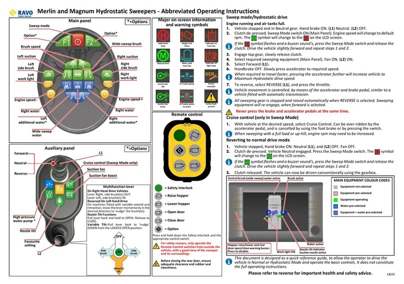
MAIN SWEEPING PANEL SWITCHES (FROM LEFT TO RIGHT & TOP TO BOTTOM)
HAZARD WARNING BEACONS
HIGH PRESSURE WATER PUMP
HYDROSTATIC DRIVE
HIGH PRESSURE FRONT SPRAY BAR - RAISE / LOWER
CRUISE CONTROL (PEDAL POSITION ONLY)
SIDE BRUSH - ON / OFF
SUCTION NOZZLE - RAISE / LOWER
WIDESWEEP BRUSH - ON / OFF
SIDE BRUSH & SUCTION NOZZLE WATER SPRAYS - ON / OFF
SUCTION NOZZLE ADDITIONAL WATER - ON / OFF
WIDESWEEP WATER SPRAYS - ON / OFF
WORK LIGHTS - ON / OFF
SIDE BRUSH PRESSURE - UP
SIDE BRUSH PRESSURE - DOWN
WIDESWEEP PRESSURE - UP
Continued...

SCARAB HYDROSTATIC TRUCK-MOUNTED SWEEPERS
5 Operator’s Manual Original Issue - 28 November 2006
WIDESWEEP PRESSURE - DOWN
SUCTION FAN - ON / BOOST
BRUSH SPEED ADJUSTMENT
FRONT BRUSH - RAISE / LOWER
FRONT BRUSH - IN / OUT
FRONT BRUSH + WATER SPRAY - ON
HOPPER BODY - RAISE / LOWER
SAFETY INTERLOCK - HOPPER & REAR DOOR
REAR DOOR - OPEN
REAR NOZZLE OPTION ON MAGNUM PLUS ONLY
REAR NOZZLE - RAISE / LOWER
REAR NOZZLE - TILT
REAR WORK LIGHTS - ON / OFF
SPARE
DOOR PANEL SWITCHES
SIDE BRUSH IN/OUT
BRUSH MASTER (RAISES / LOWERS ALL PRE-SELECTED SWEEP GEAR)
PNEUMATIC SUCTION NOZZLE TILT - MOMENTARY OR LATCHED
HYDRAULIC SUCTION NOZZLE TILT - UP / DOWN
THIS SYMBOL INDICATES OPTIONAL EQUIPMENT FITS. - INDICATES MAGNUM + ONLY
SWITCH OPERATING SYMBOLS

LCD SCREEN INFORMATION
SWEEP MODE (PANEL ON)
UPPER ROW SUCTION FAN SPEED
LOWER ROW
ROAD SPEED / ANY ACTIVE WARNINGS (SEE BELOW)
COMMON WARNINGS (number & text) & OPERATING CONDITIONS BUZZER
1: LOW OIL LEVEL, STOP (Engine running / All switches disabled *)YES
6: LOW OIL LEVEL (Engine NOT running / All switches disabled *)NO
2: HIGH OIL TEMP (Panel is ON / Engine running) YES
3: LOW BATTERY (When battery signal less than 23 Volts) YES
4: LOW WATER (Panel is ON / H-P pump switch is disabled) NO
5: HOPPER UP NO
7: PEDAL OUT OF RANGE (Hydrostatic Drive Potentiometer) NO
8: LOAD INDICATOR (optional) NO
DRIVE MODE (IGN ON / PANEL OFF)
UPPER ROW SCARAB SWEEPERS
LOWER ROW ENGINE SPEED (rpm)
*All switches EXCEPT Panel ON/STANDBY, Work-lights and Beacons are disabled.
SCARAB HYDROSTATIC TRUCK-MOUNTED SWEEPERS
Original Issue - 28 November 2006 Operator’s Manual 6
OPERATING ADVICE
Please remember, the information provided in this handbook is designed to
ensure that the Scarab sweeper operates both safely and efficiently.
A poorly maintained machine will become unreliable, inefficient and
potentially dangerous. Always observe the recommended maintenance
and safety related advice provided.
Many supposed operating problems can be traced to a lack of simple
daily maintenance. Going out to sweep in a machine that has blocked
screens, a dirt encrusted suction fan, poorly adjusted suction nozzles or
brushes is not only a waste of time; it is also a waste of fuel.
Unless it is wet or raining, ALWAYS use the low-pressure water spray system
when sweeping. This will not only reduce the amount of dust generated, it
will also ensure more efficient collection of material. This is because wet
material is heavier and will drop more readily from the air stream inside the
hopper. If swept dry more of the finer material will pass through the
screens, wearing out the fan blades on its way back to the environment
behind you.

SCARAB HYDROSTATIC TRUCK-MOUNTED SWEEPERS
7 Operator’s Manual Original Issue - 28 November 2006
THE CANbus SYSTEM (* INDICATES OPTIONAL EQUIPMENT)
The CANbus system comprises two control panels (main and auxiliary) and
a number of control nodes (normally seven). The system controls and
monitors all sweeper functions and maintains a log of various operating
parameters such as operating hours and any fault conditions that might
occur. The main panel contains a microchip which holds all the program
information and the data logs.
Control nodes: These are located adjacent to the systems they control.
Switches: The CANbus control panels use touch switches; these are
covered by a flexible overlay to identify their functions. The various types
of switch function are grouped in two ways.
Firstly they are colour coded as follows:
ORANGE = Electrical functions such as lighting.
RED = Critical functions (e.g. Hopper Raise).
PALE GREEN = Sweeping functions.
BLUE =WaterSprayfunctions.
Secondly, switches that control functions that are available either on/or
with both sides of the machine, e.g. side brushes and widesweep, are
grouped with left, right and centre function controls being positioned
accordingly on the panel. These are positioned within the light grey area
in the centre of the control panel.
Each switch has a red LED located at its upper left hand corner. This
illuminates when the switch is ON (latched) or PRESSED (non-latching).
Most switches are of the latching type (press once to turn ON and again
to turn OFF) however there are a number of non-latching switches. These
will only function while they are held down and are as follows:
(a) Safety Interlock
(b) Hopper Body RAISE
(c) Hopper Body LOWER
(d) Rear Door OPEN
(e) Momentary Nozzle Tilt
The main panel also incorporates a Liquid Crystal Display (LCD) screen
and a light-sensor.
The LCD provides real-time information relevant to the operating status of
the machine, in the form of warnings or feed-back, and acts as the system
inter-face when using the self-diagnostic facility.
The light-sensor automatically controls the switch/LCD back-lighting to
ensure legibility in low ambient light conditions.

SCARAB HYDROSTATIC TRUCK-MOUNTED SWEEPERS
Original Issue - 28 November 2006 Operator’s Manual 8
MAIN PANEL SWITCH DESCRIPTIONS
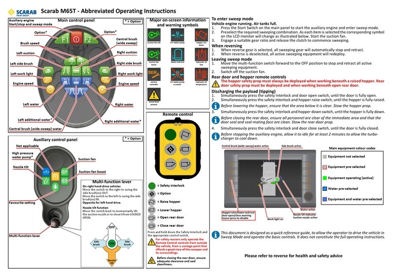
Switch functions are described from Left to Right and Top to Bottom.
NOTE:
MASTER SWEEP
Switches that are fully enabled ONLY when the Master Switch is
ON or Sweep Mode is ON are identified by the following symbols.
Fig. 1 Main Control Panel Layout
BEACONS
LEFT HAND
LEFT NOZZLE
WIDESWEEP
LEFT SIDE WATER
EXTRA WATER
RIGHT HAND
RIGHT NOZZLE
RIGHT SIDE WATER
EXTRA WATER
LEFT SIDE RIGHT SIDE
SIDE BRUSH UP/ WIDESWEEP UP/
INCREASE BRUSH SPEED
REAR WORK LIGHTS •
HOPPER RAISE/LOWER
SAFETY INTERLOCK
HOPPER DOOR
LIQUID CRYSTAL DISPLAY
AMBIENT LIGHT
SENSOR
(LCD SCREEN)
WORK LIGHTS
DOWN PRESSURE •
RIGHT NOZZLE •
RAISE/LOWER
SIDE-BRUSH
WORK LIGHTS
DOWN PRESSURE •
SIDE-BRUSH
RAISE/LOWER
LEFT NOZZLE •
SUCTION FAN
FAN BOOST
OPEN
WIDESWEEP WATER
MAIN PANEL
When in Sweep Mode:
UPPER LINE = FAN SPEED
LOWER LINE = ROAD SPEED / WARNINGS
H-P WATER PUMP *
H-P SPRAYBAR
RAISE/LOWER *
CRUISE CONTROL
*OPTIONAL EQUIPMENT
HYDROSTATIC
DRIVE
FRONT BRUSH RAISE/LOWER *
ON/OFF + WATER SPRAY *
SWING IN/OUT *
X
N
A
FUNCTION IS NOT APPLICABLE
IN THIS SWEEPER CONFIGURATION
X
N
A
BEACON SWITCH -Press to operates all hazard beacons fitted to the
vehicle. Red LED illuminates when active.
HIGH-PRESSURE WATER PUMP SWITCH *- Press to start the H-P
water pump. Red LED will illuminate when the feature is selected.
The switch becomes disabled (symbol not illuminated) and the
pump will not operate if the water level in the tank is insufficient.
Continued...

SCARAB HYDROSTATIC TRUCK-MOUNTED SWEEPERS
9 Operator’s Manual Original Issue - 28 November 2006
HYDROSTATIC GEARBOX SWITCH - Press to engage hydrostatic drive.
There are two LEDs: the RED LED indicates when the vehicle is in
conventional drive mode and the GREEN LED indicates when the
vehicle is in hydrostatic drive mode.
NOTE:
The gearbox will automatically disengage when reverse gear is selected
PANEL STAND-BY MODE / SWEEP MODE SWITCH - Press to turn the sweeper
panel ON or OFF. Red LED illuminates when sweep mode is selected. If the
panel is left on when the ignition is turned OFF, it will resume in this mode
the next time the ignition is turned ON. Engine will automatically resume at
previous Sweep Mode speed setting.
HIGH-PRESSURE SPRAY BAR RAISE LOWER SWITCH *- Press to lower the
spray bar. The red LED will illuminate when the feature is selected.
The switch is not enabled until the H-P pump is switched ON.
Switching the pump OFF will cause the spray bar to be raised.
LEFT HAND SIDE-BRUSH SWITCH - Press to start the side-brush. The red LED
illuminates when the feature is selected. Brush will not deploy until the
Master Switch is activated. On single-sweep machines the non-sweeping
side’s switch-backlight and LED will not illuminate. See also side brush
SWING IN/OUT switch.
LEFT HAND SIDE-BRUSH SWITCH - Press to start the side-brush. The red
LED illuminates when the feature is selected. Brush will not deploy
until the Master Switch is activated. On single-sweep machines the
non-sweeping side’s switch/LED will not illuminate. See also side
brush SWING IN/OUT.
LEFT HAND SUCTION NOZZLE RAISE/LOWER SWITCH - Press to lower the
suction nozzle. The red LED illuminates when the feature is selected.
On single-sweep machines the non-sweeping side’s switch / LED will
not illuminate.
WIDESWEEP BRUSH SWITCH - Press to start the widesweep brush. The
red LED illuminates when the feature is selected.
RIGHT HAND SUCTION NOZZLE RAISE/LOWER SWITCH - Press to lower
the suction nozzle. The red LED illuminates when the feature is
selected. On single-sweep machines the non-sweeping side’s switch
/ LED will not illuminate.
RIGHT HAND SIDE-BRUSH SWITCH - Press to start the side-brush. The
red LED illuminates when the feature is selected. On single-sweep
machines the non-sweeping side’s switch/LED will not illuminate. See
also side brush SWING IN/OUT switch.
LEFT HAND SIDE-BRUSH/NOZZLE WATER SWITCH - Press to start the
dust-suppression water jets for the side-brush and suction nozzle. The
red LED illuminates when the feature is selected.

Fig. 2 Main Control Panel Layout
BEACONS
LEFT HAND
LEFT NOZZLE
WIDESWEEP
LEFT SIDE WATER
EXTRA WATER
RIGHT HAND
RIGHT NOZZLE
RIGHT SIDE WATER
EXTRA WATER
LEFT SIDE RIGHT SIDE
SIDE BRUSH UP/ WIDESWEEP UP/
INCREASE BRUSH SPEED
REAR WORK LIGHTS •
HOPPER RAISE/LOWER
SAFETY INTERLOCK
HOPPER DOOR
LIQUID CRYSTAL DISPLAY
AMBIENT LIGHT
SENSOR
(LCD SCREEN)
WORK LIGHTS
DOWN PRESSURE •
RIGHT NOZZLE •
RAISE/LOWER
SIDE-BRUSH
WORK LIGHTS
DOWN PRESSURE •
SIDE-BRUSH
RAISE/LOWER
LEFT NOZZLE •
SUCTION FAN
FAN BOOST
OPEN
WIDESWEEP WATER
MAIN PANEL
When in Sweep Mode:
UPPER LINE = FAN SPEED
LOWER LINE = ROAD SPEED / WARNINGS
H-P WATER PUMP *
H-P SPRAYBAR
RAISE/LOWER *
CRUISE CONTROL
*OPTIONAL EQUIPMENT
HYDROSTATIC
DRIVE
FRONT BRUSH RAISE/LOWER *
ON/OFF + WATER SPRAY *
SWING IN/OUT *
X
N
A
FUNCTION IS NOT APPLICABLE
IN THIS SWEEPER CONFIGURATION
X
N
A
SCARAB HYDROSTATIC TRUCK-MOUNTED SWEEPERS
Original Issue - 28 November 2006 Operator’s Manual 10
LEFT HAND SUCTION NOZZLE - ADDITIONAL WATER SWITCH *- Press to
start the additional water jets for the suction nozzle. The red LED
illuminates when the feature is selected.
WIDE SWEEP WATER SWITCH - Press to start the dust-suppression water
jets for the widesweep brush. The red LED illuminates when the
feature is selected.
RIGHT HAND SUCTION NOZZLE - ADDITIONAL WATER SWITCH *- Press
to start the additional dust-suppression water jets for the suction
nozzle. The red LED illuminates when the feature is selected.
RIGHT HAND SIDE-BRUSH/NOZZLE WATER SWITCH - Press to start the
dust-suppression water jets for the side-brush and suction nozzle. The
red LED illuminates when the feature is selected.

SCARAB HYDROSTATIC TRUCK-MOUNTED SWEEPERS
11 Operator’s Manual Original Issue - 28 November 2006
LEFT HAND WORK-LIGHTS - Press to turn the work-lights ON. The red LED
illuminates when the feature is selected.
NOTE:
Please refer to Page 16 for details on pre-setting the brush air pressure-
regulator for use with the following four control switches.
SIDE-BRUSH ‘UP’ PRESSURE SWITCH *- Press to allow a controlled
amount of pressure to the bottom of the brush lift ram(s) and reduce
the brush’s surface pressure. Use in conjunction with the air-pressure
regulator. The red LED illuminates when the feature is selected.
SIDE-BRUSH ‘DOWN’ PRESSURE SWITCH *- Press to allow a controlled
amount of pressure to the top of the brush lift ram(s) and increase
the brush’s surface pressure. Use in conjunction with the air-pressure
regulator. The red LED illuminates when the feature is selected.
WIDESWEEP ‘UP’ PRESSURE SWITCH *- Press to allow a controlled
amount of pressure to the bottom of the brush lift ram(s) and reduce
the brush’s surface pressure. Use in conjunction with the air-pressure
regulator. The red LED illuminates when the feature is selected.
WIDESWEEP ‘DOWN’ PRESSURE SWITCH *- Press to allow a controlled
amount of pressure to the top of the brush lift ram(s) and increase
the brush’s surface pressure. Use in conjunction with the air-pressure
regulator. The red LED illuminates when the feature is selected.
RIGHT HAND WORK-LIGHTS - Press to turn the work-lights ON. The red LED
illuminates when the feature is selected.
SUCTION FAN SWITCH - Press to start the fan. Red LED illuminates
when the fan is ON. Fan speed (approximately 2000 rpm) is
displayed on the LCD screen. This switch remains active when the
fan-boost switch is pressed.(See also Fan Boost on Page 12)
BRUSH SPEED (+) SWITCH - Press to increase brush speed to 125 rpm.
The red LED illuminates when the feature is active. Press again to
return to normal brush speed (If Brush Speed (++) is selected (See
Page 12) when this feature is active Brush Speed (+) will be
automatically deselected).
FRONT BRUSH RAISE/LOWER SWITCH - Press to lower the front brush
assembly. The red LED illuminates when the feature is selected.
FRONT BRUSH ON/OFF + WATER SPRAY SWITCH - Press to start the front
brush and simultaneously turn on the dust suppression water spray.
The red LED illuminates when the feature is selected.
HOPPER RAISE SWITCH - Press and hold down simultaneously with the
safety interlock switch to raise the hopper. the red LED illuminates as
soon as the hopper starts to rise.
NOTE:
For details of externally mounted hopper controls refer to Page 22.

Fig. 3 Main Control Panel Layout
BEACONS
LEFT HAND
LEFT NOZZLE
WIDESWEEP
LEFT SIDE WATER
EXTRA WATER
RIGHT HAND
RIGHT NOZZLE
RIGHT SIDE WATER
EXTRA WATER
LEFT SIDE RIGHT SIDE
SIDE BRUSH UP/ WIDESWEEP UP/
INCREASE BRUSH SPEED
REAR WORK LIGHTS •
HOPPER RAISE/LOWER
SAFETY INTERLOCK
HOPPER DOOR
LIQUID CRYSTAL DISPLAY
AMBIENT LIGHT
SENSOR
(LCD SCREEN)
WORK LIGHTS
DOWN PRESSURE •
RIGHT NOZZLE •
RAISE/LOWER
SIDE-BRUSH
WORK LIGHTS
DOWN PRESSURE •
SIDE-BRUSH
RAISE/LOWER
LEFT NOZZLE •
SUCTION FAN
FAN BOOST
OPEN
WIDESWEEP WATER
MAIN PANEL
When in Sweep Mode:
UPPER LINE = FAN SPEED
LOWER LINE = ROAD SPEED / WARNINGS
H-P WATER PUMP *
H-P SPRAYBAR
RAISE/LOWER *
CRUISE CONTROL
*OPTIONAL EQUIPMENT
HYDROSTATIC
DRIVE
FRONT BRUSH RAISE/LOWER *
ON/OFF + WATER SPRAY *
SWING IN/OUT *
X
N
A
FUNCTION IS NOT APPLICABLE
IN THIS SWEEPER CONFIGURATION
X
N
A
SCARAB HYDROSTATIC TRUCK-MOUNTED SWEEPERS
Original Issue - 28 November 2006 Operator’s Manual 12
SAFETY INTERLOCK SWITCH - Press and hold while operating the in-
cab hopper or rear door switches. The red LED illuminates when the
switch is activated.
SUCTION FAN ‘BOOST’ SWITCH - Press to activate the fan boost
mode. This increases fan speed to approx. 2200 rpm. The red LED
illuminates while the feature is selected and the fan speed indicated
on the LCD will change to show approximately 2200 rpm. Press again
to revert to normal fan speed.
BRUSH SPEED (++) SWITCH - Press to increase brush speed to 150 rpm.
The red LED illuminates when the feature is active. If this feature is
selected when Brush Speed (+) is already active it will automatically
deselect Brush Speed (+). Press again to revert to normal brush speed.

SCARAB HYDROSTATIC TRUCK-MOUNTED SWEEPERS
13 Operator’s Manual Original Issue - 28 November 2006
REAR WORK-LIGHTS SWITCH *- Press to turn on the rear-mounted
work-lights. The red LED illuminates while the feature is active.
HOPPER LOWER SWITCH - Press and hold down simultaneously with
the safety interlock switch to lower the hopper. the red LED will
remain illuminated until the hopper is fully in the lowered position.
REAR DOOR OPEN SWITCH - Press and hold down simultaneously with
the safety interlock switch to open the rear door. Red LED illuminates
when the switch is operated.
NOTE:
Ensure that the suction fan is OFF. The door cannot open while the suction fan
is running due to the low pressure it creates inside the hopper.
For externally mounted rear door controls refer to Page 23.
THE LCD SCREEN
The LCD Screen provides the operator with information on fluid level/
temperature warnings and confirmation of sweeper functions such as fan
speed (refer to Page 6 for details).
AUXILIARY SWITCH PANEL (Located Adjacent To Driver’s Door)
FRONT BRUSH SWING IN/OUT SWITCH - Press to swing the brush our
and press again to swing it in. The red LED illuminates while the brush
is in the swung OUT position.
NOZZLE TILT SWITCH (MOMENTARY MODE) - Press and hold to tilt the
suction nozzle for larger items, such as bottles. The red LED illuminates
when the switch is activated. Release the switch to revert to normal
position.
BRUSH MASTER SWITCH - Press to deploy all sweeping equipment selected
on the main control panel. The red LED illuminates while the feature is
active. Press again to stop and raise all active items of sweeping
equipment.
NOZZLE TILT SWITCH (LOCKING MODE) - Press to tilt the nozzle
permanently to the raised position. The red LED illuminates while the
feature is active. Press again to return the nozzle to the normal
position.
FORWARD/REVERSE LEVER - Lift collar to release from Neutral and move the
lever in the desired direction to activate the hydrostatic transmission.

Fig. 4 Main & Auxiliary (Door) Panel Layouts
AUXILIARY (DOOR) PANEL
BRUSH SWING-OUT
MASTER SWITCH
NOZZLE TILT (MOMENTARY)
NOZZLE TILT (LOCKING)
BEACONS
LEFT HAND
LEFT NOZZLE
WIDESWEEP
LEFT SIDE WATER
EXTRA WATER
RIGHT HAND
RIGHT NOZZLE
RIGHT SIDE WATER
EXTRA WATER
LEFT SIDE RIGHT SIDE
SIDE BRUSH UP/ WIDESWEEP UP/
INCREASE BRUSH SPEED
REAR WORK LIGHTS *
HOPPER RAISE/LOWER
SAFETY INTERLOCK
HOPPER DOOR
LIQUID CRYSTAL DISPLAY
AMBIENT LIGHT
SENSOR
(LCD SCREEN)
WORK LIGHTS
DOWN PRESSURE *
RIGHT NOZZLE *
RAISE/LOWER
SIDE-BRUSH
WORK LIGHTS
DOWN PRESSURE *
SIDE-BRUSH
RAISE/LOWER
LEFT NOZZLE *
SUCTION FAN
FAN BOOST
OPEN
WIDESWEEP WATER
MAIN PANEL
When in Sweep Mode:
UPPER LINE = FAN SPEED
LOWER LINE = ENGINE SPEED/WARNINGS
H-P WATER PUMP *
H-P SPRAYBAR
RAISE/LOWER *
CRUISE CONTROL
*OPTIONAL EQUIPMENT
FRONT BRUSH RAISE/LOWER *
ON/OFF + WATER SPRAY *
SWING IN/OUT *
HYDROSTATIC
DRIVE
FORWARD/REVERSE LEVER
X
N
A
X
N
A
FUNCTION IS NOT APPLICABLE
IN THIS SWEEPER CONFIGURATION
F
R
N
SCARAB HYDROSTATIC TRUCK-MOUNTED SWEEPERS
Original Issue - 28 November 2006 Operator’s Manual 14

SCARAB HYDROSTATIC TRUCK-MOUNTED SWEEPERS
15 Operator’s Manual Original Issue - 28 November 2006
REAR-MOUNTED SUCTION NOZZLE OPTION
It is possible to equip the Magnum Plus model with a special rear door
assembly that incorporates a pair of rear-mounted suction nozzles and
their associated high-pressure water spray bars. The inclusion of this option
in the vehicle specification requires a different main control panel to the
standard layout. This involves changes to the two lower-most rows of
switches (Refer to Fig. 5). To incorporate the rear nozzle controls the
following switches have been relocated:
• Front brush On + Water
• Front brush Raise/Lower
• Front brush Swing IN/OUT
and the following switches have been removed:
• Safety Interlock for Hopper and Rear Door
• Hopper RAISE / LOWER
• Rear door OPEN
To activate the hopper and rear door controls, use the external switches
mounted adjacent to the near side suction tube (refer to Pages 20 & 22).
Fig. 5 Alternative Control Panel layout - Rear-Mounted Suction Nozzles
REAR NOZZLES
RAISE/LOWER
*
REAR NOZZLES
TILT
*
REAR WORK LIGHTS
*
FRONT BRUSH ON/OFF FRONT BRUSH RAISE/LOWER
*
FRONT BRUSH SWING IN/OUT
*
SPARE SWITCHES
FOR OPTIONAL FUNCTIONS
+ WATER
*

SCARAB HYDROSTATIC TRUCK-MOUNTED SWEEPERS
Original Issue - 28 November 2006 Operator’s Manual 16
ADDITIONAL CONTROLS & INSTRUMENTS
CAUTION:
Do not exceed a pressure of 2.5 bar when adjusting brush pressure settings.
Failure to comply could result in damage to the pneumatic system.
PRESSURE REGULATOR
PRESSURE GAUGE
Externally mounted widesweep pressure
controls shown.
The side-brush controls are similar but mounted
in the cab and positioned according to cab layout
or customer preference.
AIR-PRESSURE REGULATOR *- Used
to adjust the amount of up/down-
thrust applied to the brush(es) ¤.
AIR-PRESSURE GAUGE *- Indicates
the amount of pressure being applied
to the brush(es) ¤.
¤Side-brush regulators/gauges are
mounted inside the cab.
Widesweep regulators/gauges are
located externally to the rear of the
near-side suction spigot mount.
See overleaf for Operating Modes ...

SCARAB HYDROSTATIC TRUCK-MOUNTED SWEEPERS
17 Operator’s Manual Original Issue - 28 November 2006
OPERATING MODES
There are two driving modes, Normal & Hydrostatic (Sweep), these
are selected using the SWEEP MODE switch on the control panel.
This switch has to LEDs, one green and one red. These are used to
indicate which drive mode is currently in operation as follows:
• Green = Normal drive mode
• Red = Hydrostatic drive (sweep mode)
ENGAGING HYDROSTATIC DRIVE
REFER TO THE HEALTH & SAFETY INFORMATION ON Page 3
CAUTION:
The engine must be running and the air tanks/pneumatic system must be fully
pressurised before attempting to engage hydrostatic drive mode.
The hydrostatic gearbox has a motion sensor. This will not allow engagement of
hydrostatic drive until the vehicle is stationary.
1. Stop the vehicle apply the parking brake and select Neutral.
2. Switch on hazard warning beacons.
3. With the engine running, depress the clutch pedal and press
the Sweep Mode switch. The switch’s LED indicators will
change from GREEN to RED, confirming that hydrostatic
drive has engaged successfully.
4. Select the highest forward gear available and release the clutch
pedal. The vehicle is now in hydrostatic drive and may be driven
without use of the clutch.
NOTE:
If the Green LED flashes ON/OFF or you hear gears grating, the drive gears in
the transfer box have not meshed correctly. If the clutch is engaged at this
point, the engine will probably stall. Refer to Step 5.
5. If Hydrostatic drive fails to engage, press Sweep Mode to restore
Normal Drive mode. Engage first gear, release the hand brake and
move the vehicle forward slightly. Repeat Steps 1. to 4.
6. Set the required engine speed (Refer to the back of this handbook
for vehicle/chassis specific instructions).
NOTE:
Mercedes engines assume sweep speed automatically when in sweep mode.
7. Switch on the suction fan, selecting Normal (approx.
2000 rpm) or Boost (approx. 2200 rpm) as required. If Boost is
selected (Page 18) remember that increased engine speed
might be necessary. Fan speed can be confirmed by
referring to the LCD on the main sweeper control panel.
8. Select the desired configuration of brushes/suction boxes and
water sprays (any combination of brushes and water can be
selected). Switch on work-lights as required.
This manual suits for next models
2
Table of contents
Other Scarab Blower manuals

Scarab
Scarab Merlin Manual

Scarab
Scarab Merlin User manual

Scarab
Scarab Mistral Manual

Scarab
Scarab M25H User manual

Scarab
Scarab M6 User manual

Scarab
Scarab Merlin Series Operating instructions

Scarab
Scarab M65T User manual

Scarab
Scarab M6 User manual

Scarab
Scarab M65T Manual

Scarab
Scarab Mistral Operating instructions
Popular Blower manuals by other brands

Ryobi
Ryobi WHISPER Series Operator's manual

Makita
Makita EB7650TH technical information

Ryobi
Ryobi RGBV3100 Operator's manual

Spear & Jackson
Spear & Jackson SPJBV 3200 operating instructions

Empire Comfort Systems
Empire Comfort Systems CIB3-2 installation instructions

NVE
NVE 4307 Series Owner's manual & operating instructions