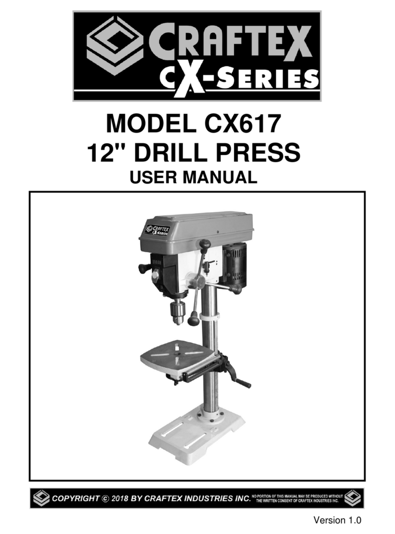
Craftex CS Series User manual

MODEL CX618 – USER MANUAL

2
TABLE OF CONTENTS
Introduction …………………………………………………………………………………….....3
General Safety Instructions for Machines……………………………………………….……..4
Specific Safety Instructions……………………………………………………………….……..5
Features…………………………………………………………………………………………...6
Physical Features………………………………………………………………………………...8
Assembly & Adjustments.…..……………………………………………………………….…10
Feed Handles…………………………………………………………………………………....11
Proper Grounding…………………………………………………………………………….…..7
Mounting the Drill Press……………………………………………………………………..…12
Installing the Arbor and Chuck…………………………………………………………….…...12
Removing the Chuck…………………………………………………………………....……...13
Raise or lower the table……………………………………………………………………......13
Tilt the table………………………………………………..…………………………………….13
Squaring the Table to the Drill Bit……………………………………………………………..14
Installing a Drill Bit…………………………………………………………..…………………..14
Adjusting the Laser......................................................................................……………..15
Spindle Return Spring..................................................................................……………..15
Angular Play of the Spindle..........................................................................……………..16
Drive Belt Replacement……………………………………………………………………..….16
Drilling Speeds……………………………………………………………………..…………...19
Maintenance……….......................................................................................…………….21
Troubleshooting………………………………………………………………………….…….. 22
Parts List…………………………………………………………………………………………23
Warranty…………………………………………………………………………………………24

3
INTRODUCTION
Welcome the Family of quality machinery from Busy Bee Tools. The CX618
is a robust drill press that will provide you with years of excellent service. As
will all our products we strive to attain the best quality and the best possible
price. This CX618 is the newest addition to the family and with its many
features you will find that it is well suited for a variety of tasks and operations.
The variable speed mechanism will allow for easy and quick speed changes
without the need to change the position of the belts on different sheaves of
the pulley. Thereby allowing more time spent on your projects than on the
setup and re-setup of the machine every time your conditions change.
Every attempt has been made to ensure that the information in this users
manual is accurate and up to date. As there are always some changes to
manufacturing processes and procedures it is possible that changes made
are not immediately reflected in the current manual. We welcome feedback
from our users to assist us in keeping our manuals current. Should you
discover something that we could improve or any features of your drill press
that is not in the manual please contact our customer service department at
manual and the actual product.
In the event that you discover that there are any parts missing or something
isn’t quite right with your machine please call us at Customer Service 905 738
5115 x 6506 and we will be happy to assist you.

4
GENERAL SAFETY INSTRUCTIONS FOR MACHINES
Extreme caution should be used when operating all power tools. Know your power
tool, be familiar with its operation, read through the user manual, and practice safe
usage procedures at all times.
Read and become familiar with this
entire instruction manual. Learn the tools
applications, limitations, and possible
hazards.
CONNECT your machine ONLY to the
matched and specific power source.
ALWAYS wear safety glasses
respirators, hearing protection and
safety shoes, when operating your
machine.
DO NOT wear loose clothing or jewelry
when operating your machine. Wear
protective hair covering.
ALWAYS keep your work area clean,
uncluttered and well lit. DO NOT work on
floor surfaces that are slippery with
sawdust or wax
BE ALERT! DO NOT use prescription
or other drugs that may affect your ability
or judgment to safely use your machine.
DISCONNECT the power source when
changing drill bits, hollow chisels, router
bits, shaper heads, blades, knives or
making other adjustments or repairs.
NEVER leave a tool unattended while it is
in operation.
NEVER allow unsupervised or untrained
person to operate the machine.
NEVER reach over the table when the tool
is in operation.
ALWAYS keep blades, knives and bits
sharpened and properly aligned.
ALWAYS keep the guards in place when
operating your drill press.
ALWAYS use push sticks and feather
boards to safely feed your work through
the machine.
ALWAYS make sure that any tools used
for adjustments are removed before
operating the machine.
ALWAYS keep bystanders safely away
while the machine is in operation.
NEVER attempt to remove jammed cutoff
pieces until the blade has come to a full
stop.

5
SPECIFIC SAFETY INSTRUCTIONS FOR CX618
READ AND UNDERSTAND the user
manual before operating the CX617.
ALWAYS WEAR safety glasses for the
protection of your eyes while operating
this machine.
WEAR PROPER APPAREL. Loose
clothing, gloves neckties, rings,
bracelets, or other jewelry may get
caught in moving parts of the machine.
Wear protective hair covering to contain
long hair. Do not wear gloves and keep
your fingers and hair away from rotating
parts.
KEEP GUARDS in place. Safeguards
must be kept in place and in working
order. Do not operate the drill press
unless the chuck guard is in its position,
guarding the chuck.
MAKE SURE the workpiece is properly
clamped to the table before operating the
machine. Never hold the workpiece by
hand when using the mill.
MAKE SURE the cutting tool is sharp,
not damaged and properly secured in the
chuck before you start the machine.
SELECT The proper spindle speed for the
type of work and material you are cutting.
Let the spindle reach to its full speed
before beginning a cut.
NEVER LEAVE the machine unattended
while it is running.
ALWAYS turn off the power before
removing scrap pieces and cleaning the
machine.
SHOULD ANY PART of your tool be
missing, damaged or fail in any way, shut
off the machine immediately and remove
the plug from power source. Replace any
damaged or missing parts before
resuming operation.
MAKE SURE before installing and
removing any parts, servicing, cleaning, or
making any adjustments, the switch is in
the “OFF” position and the cord is un-
plugged from the power source.
BEFORE OPERATING your dill press
make sure you have read and understood
all the safety instructions in the manual
and you are familiar with your
DO NOT force the machine to do a job for
which it is not designed Always use the
machine for the purpose for which it was
designed.
NEVER turn the power ON with the cutting
tool contacting the workpiece
6
Shipping Dimensions:
Type.................................................................................................................................………..Carton
Content..................................................................................................................................….Machine
Dimensions………………………………………………………………………………..……….12 x 17 x 60”
Weight........................................................................................................................................ 156 lbs.
Must Ship Upright............................................................................................................................... No
Electrical:
Power Requirement.......................................................................................110V, Single-Phase, 60 Hz
Full-Load Current Rating.................................................................................................................. 8.6A
Minimum Circuit Size........................................................................................................................ 15A
Connection Type...................................................................................................................Cord & Plug
Power Cord Included......................................................................................................................... Yes
Power Cord Length............................................................................................................................ 6 ft.
Power Cord Gauge..............................................................................................................18 AWG SJT
Plug Included.................................................................................................................................... Yes
Included Plug Type.......................................................................................................................... 5-15
Switch Type................................................................................................Paddle Safety Switch w/ Key
Motor:
Horsepower…..................................................................................................................... 1 HP
Phase.................................................................................................................... Single-Phase
Amps.................................................................................................................................. 8.6 A
Speed........................................................................................................................ 1720 RPM
Type.......................................................................................... TEFC Capacitor-Start Induction
Power Transfer ....................................................................................................... V-Belt Drive
Bearings.............................................................................. Shielded & Permanently Lubricated
General Specifications
Type................................................................................................................................................ Floor
Swing.............................................................................................................................................. 15 in.
Spindle Taper................................................................................................................................... MT2
Spindle Travel................................................................................................................................... 4 in.
Max. Distance from Spindle to Column......................................................................................... 7.5 in.
Max. Distance from Spindle to Table........................................................................................ 31-1/2 in.
Number of Spindle Speeds.........................................................................................................Variable
Range of Spindle Speeds.............................................................................................. 280 – 3300 RPM
Max. Head Swivel...................................................................................................................... 360 deg.
Drilling Capacity (Mild Steel) ......................................................................................................... 3/4 in.
Drill Chuck Type................... ........................................................................................ JT33 Key Chuck
Drill Chuck Size................................................................................................................... 3/64 – 5/8 in.
Spindle Information
Distance From Spindle to Base ……….................................................................................... 48 3/4 in.
Quill Diameter …………………….............................................................................................. 2.040 in.
CX618 – DRILL PRESS
Features

7
Table Information
Max. Table Tilt (Left/Right) ……………….....................................................................................90 deg.
Table Swing...............................................................................................................................360 deg.
Table Swivel Around Center.......................................................................................................360 deg.
Table Swivel Around Column.....................................................................................................360 deg.
Max. Movement of Work Table....................................................................................................... 26 in.
Table Length............................................................................................................................ 11-3/8 in.
Table Width.............................................................................................................................. 11-3/8 in.
Floor-To-Table Height............................................................................................................. 20 – 46 in.
Construction
Table.............................................................................................................Precision-Ground Cast Iron
Column............................................................................................................................................Steel
Spindle Housing….................................................................................................................... Cast Iron
Head......................................................................................................................................... Cast Iron
Base......................................................................................................................................... Cast Iron
Paint Type/Finish.................................................................................................................Powder Coat
Other Related Information
Base Length................................................................................................................................... 18 in.
Base Width..................................................................................................................................... 11 in.
Column Diameter....................................................................................................................... 3.150 in.
Depth Stop Type............................................................................................................................... Hub
Country of Origin ........................................................................................................................... China
Warranty ...................................................................................................................................... 3 Year

8
A
Digital Speed Readout I Pulley Cover Q Location Pin
B
ON/OFF Switch J Column R Bevel Scale
C
Depth Scale K Rack STable Support Lock Handle
DChuck L Crank Handle TSpeed Control Handle
ETable M Column Base ULED Work light Switch
F Laser Switch N Base VPower Cord
GFeed Handles O Table Lock Handle W Tension Knob
HPulley Cover Knob P Bevel Lock Bold XLock Handle
CX618 – DRILL PRESS
Physical Features

9
UNPACKING
Unpack the drill press and all of its parts. Compare against the list below. Do not discard the carton or
any packaging until the drill press is completely assembled.
To protect the drill press from moisture, a protective coating has been applied to the machine’s surfaces.
Remove this coating with a soft cloth moistened with kerosene or WD-40®. Do not use acetone,
gasoline, or lacquer thinner to clean. Apply a coat of good paste wax to the table and column. Wipe all
parts with a clean dry cloth.
A Head/Motor Assembly F Table Support Lock Handle Chuck Key
B Column Assembly G Table Lock Handle L Feed Handle
C Table H Bolt M12 X 35 M Speed Handle
DBase IChuck NWedge
E Hex Keys - 3, 4, 5 J Chuck Arbor O Crank Handle

10
ASSEMBLY AND ADJUSTMENTS
WARNING: If any part is missing or damaged, do not plug the drill press in
until the missing or damaged part is repaired or replaced.
Tools needed for assembly
Socket wrench
Screwdriver
Hammer and block of
wood
Assembly:
The column assembly (column,
column support, rack, rack collar,
and table support bracket) must
be attached to the base. The
table and table support handles
must be attached to the table
support bracket. The motor
housing must be attached to the
column.
COLUMN ASSEMBLY TO BASE (Fig. 3)
1.) Place the column column base (1)
on the base (2), aligning the
column support holes to the base
holes.
2.) Install a hex head bolt (3) in each
column support hole and tighten
bolts using the socket wrench.
Fig. 3
Insert the pinion into the hole on the
side of the table support bracket from
the inside, starting with the pinion
shaft. Figure 3.
Examine the rack and note that the
gear teeth extend further on one end
than the other. The shorter end must
be positioned down. Insert the rack
into the table support bracket and
align with pocket so that the gear
teeth mesh with the rack teeth. The
end of the rack where the gear teeth
are closest to the end should be
positioned down. Slide the table
support bracket and rack onto the
column.

11
Thread the table lock handle (4)
into the front of the table support
bracket.
Align setscrew in crank handle with
flat, Figure 4, on pinion shaft and
secure using the 3mm Allen® wrench
provided.
Thread the table support lock
handle into the rear of the table
support bracket
Slide the column ring onto the
column with the inside bevel in the
down position. Figure 4. Adjust
the ring until the tip of the rack fits
inside the bevel. Tighten the
setscrew on the ring
.
Do not over tighten the
setscrew as it can crack the
ring.
Fig. 4
Drill Press Column
CAUTION: The drill press head is heavy.
To avoid injury, two people should lift it
into position.
1.) Carefully lift the drill press head
assembly (1) and position it over the
column (2).
2.) Place the mounting opening (3) on the
drill press head over the top of the
column. Make sure the drill press head is
seated properly on the column.
3.) Align the direction of the drill press
head with the direction of the base and
the table.
3.)
Tighten the set screw (4) using a hex
key.
Fig. 5
FEED HANDLES
1.) Insert the three speed handles (1) into
the threaded openings on the feed hub
(2).
2.) Manually tighten handles into
openings.
Note: When using the drill press, one or
two of the feed handles may be removed
if an unusually shaped workpiece
interferes with handle rotation.

12
SPEED HANDLE (Fig. 7)
1. Insert the feed handle (1) into the
threaded opening on the speed hub (2).
2. Manually tighten handle into opening.
Fig. 8
Mounting the Drill Press
The Drill press should be secured to the
floor to give stability to the drill press to
prevent the drill press from tipping over
Fig. 9
Install the chuck
1. Inspect and clean the taper hole in the
chick and the spindle. Remove all
grease, oil and particles from the chuck
and arbor surfaces with a clean cloth.
2. Open the chick jaws by manually turning
the chuck barrel clockwise. Make sure
the haws are completely recessed
inside the chuck.
3. Insert the chuck arbor into the chuck
4. Seat the chuck and chuck arbor on the
spindle by placing a block of wood with
a hammer (not included) Or tap the
chuck with a rubber mallet (not included)

13
Fig. 10
Remove the Chuck
1. Turn the feed handles to lower the
chuck to the lowest position.
2. Slide the wedge into the opening in the
quill and tap the wedge with a hammer
or mallet. The Chuck arbor will drop out
of the quill.
Protect the table with a piece of wood or
heavy carboard to prevent the chuck
from dropping onto the table.
RAISE OR LOWER THE TABLE
(Fig. 12 )
1. Loosen the support lock handle (1)
and turn the crank handle (2) until the
table is at the desired height.
2. Tighten the support lock handle
before drilling.
ROTATE THE TABLE (Fig. 12 )
1. Loosen the support lock handle (1)
and turn the table around the column to
the desired position.
Note: The rack should rotate around the
column with the table support bracket. If
the rack binds and does not rotate,
slightly loosen the set screw in the rack
collar.
2. Tighten the support lock before
drilling.
Fig. 12
TILT THE TABLE (Fig. 12)
1. Rotate the table clockwise with the fork
wrench. Pull out the location pin. Put the
location pin and nut in suitable area.
2. Rotate the bolt (1) counter-clockwise
with a wrench to loosen it.
3. Adjust the angle of the table.
4. Tighten the bolt with fork wrench.

14
ADJUST THE TABLE TO BE
HORIZONTAL
1. Rotate the bolt (1) counter-clockwise
with a wrench to loosen it.
2. Rotate the table to 0˚.
3. Hit the location pin (2) into the location
hole in the table support with a hammer.
4. Tighten the nut of the location pin (2)
slightly.
5. Lock the bolt (1) with wrench.
INSTALLING A DRILL BIT (Fig. 13)
1. Place the chuck key (1) into the side
keyhole of the chuck (2), meshing the key
with the gear teeth.
2. Turn the chuck key counter-clockwise
to open the chuck jaws (3).
3. Insert a drill bit (4) into the chuck far
enough to obtain the maximum grip of the
chuck jaws.
4. Center the drill bit in the chuck jaws
before the final tightening of the chuck.
5. Tighten the chuck jaws using the chuck
key to ensure that the drill bit will not slip
while drilling.
6. Remove the chuck key.
SQUARING THE TABLE TO THE
DRILL BIT
(Fig. 14)
1. Insert a 3” long drill bit (1) into the
chuck (2) and tighten the jaws with the
chuck key.
2. Raise the table with the crank handle
(3). Lock the table (4) approximately 1”
below the drill bit.
3. Place a combination square (not
included) on the table as shown, placing
the long straight edge of the combination
square against the drill bit. Make sure the
drill bit is parallel/aligned exactly to the
straight edge of the square.
4. If an adjustment is needed, loosen the
bevel lock bolt (6) with a wrench.
5. Tilt the table slightly, until the
combination straight edge is aligned
perfectly with the drill bit.
6. Tighten the bevel lock when square.
Note: Adjustments for the correct
function of your drill press return spring
have been done by the factory. Please
do not modify them. However,
prolonged use of the drill press may
make some readjustments

15
ADJUSTING THE LASER
WARNING: Do not stare directly at the
laser beam. Please observe all safety
rules.
• Never aim the beam at a person or an
object other than the workpiece.
• Do not project the laser beam into the
eyes of others.
• Always make sure the laser beam is
aimed at a workpiece that does not
possess reflective surfaces, as the
laser beam could project into your
eyes or the eyes of others.
1. Place a workpiece on the table.
2. Turn the laser switch (1) to the ON
position.
3. Lower the drill bit to meet the workpiece
(2). The two laser lines should cross
where the drill meets the workpiece.
4. If the laser needs to be adjusted:
a. Using a 3 mm hex key, turn the
laser adjustment set screws (3) counter-
clockwise.
b. Rotate the laser light housing (4)
until the two laser lines intersect where
the drill meets the workpiece. DO NOT
stare directly at the laser lines.
5. Re-tighten the adjustment set screws
(3).
SPINDLE RETURN SPRING
The spindle is equipped with an auto-
return mechanism. The main components
are a spring and a notched housing. The
spring was properly adjusted at the
factory and should not be readjusted
unless absolutely necessary.
1. Unplug the drill press.
2. Place a screwdriver into the loop (1) to
hold the spring in place.
3. Loosen the two housing nuts (2)
approximately 1/4” (6 mm). Do not
remove the nuts from the threaded shaft.
Do not allow the spring or spring housing
to slip out of control.
4. While firmly holding the spring housing
(3), carefully pull the spring housing out
until it clears the raised notch (4).
5. Turn the housing so that the next notch
(5) is engaged with the raised notch (4).
• To increase the spindle return tension,
turn the spring housing counter clockwise.
• To decrease the tension, turn the spring
housing clockwise.

16
6. Tighten the two housing nuts. Do not
overtighten the two nuts. If the nuts are
tightened too much, the movement of the
spindle and feed handles will become
sluggish.
ANGULAR “PLAY” OF
THE SPINDLE
Move the spindle to the lowest downward
position and hold in place. Try to make
the spindle revolve around its axis while
also moving it with a side motion. If there
is too much “play”, proceed as follows:
1. Loosen the lock nut (1).
2. Without obstructing the upward and
downward motion of the spindle, turn the
screw (2) clockwise to eliminate the
“play.” Note: A little bit of “play” is normal.
3. Tighten the lock nut (1).
REPLACING THE BELT
WARNING: Disconnect the drill press
from the power source before replacing
the belt.
Belt tension and drill press speed is
controlled by automatic adjustments made
to the diameter of the front spindle when
the drive handle is moved.
Note: See page 19 for information on the
variable speed function of this drill press.
1. Remove the screw that secures the
housing cover (1). Open the housing
cover.
2. Remove the belt (2) from the housing
cover if it is broken. If it is not broken, but
is too stretched to operate correctly, work
the belt off the drive (motor) spindle (3).
Then remove the belt from the front
spindle (4).
3. Replace the belt by putting a new belt
over the front spindle (4) and carefully
sliding the belt over the drive (motor)
spindle (3).
WARNING: Do not change the drive
speed when the drill press is turned off.

17
DRILL PRESS ON/OFF
SWITCH (Fig 19)
1. To turn the drill press ON, insert the
yellow safety key (1) into the switch
housing (2). As a safety feature, the
switch cannot be turned ON without the
safety key.
2. Flip the switch upward to the ON
position.
3. To turn the drill press OFF, flip the
switch downward.
4. To lock the switch in the OFF position,
remove the safety key (1) from the switch.
Store the safety key in a safe place.
LIGHT AND LASER LINE ON/OFF
SWITCHES (Fig. 20)
The light switch (3) is located on the
lamp cover.
The laser switch (4) is located
below the ON/OFF switch on the
right.
POSITION THE TABLE AND
WORKPIECE
Always place a piece of backup
material (1) (wood, plywood, etc.) on
the table underneath the workpiece
(2). This will prevent splintering on the
underside of the workpiece as the drill
bit breaks through.
To keep the material from spinning out
of control, it must contact the left side
(3) of the column as illustrated or be
clamped (4; not included) to the table.
Note: For small workpieces that
cannot be clamped to the table, use a
drill press vise (not included). The vise
must be clamped or bolted to the table
to avoid injury.

18
GENERAL DRILLING GUIDELINES -
DRILLING A HOLE
WARNING: To prevent the workpiece and
the backup material from slipping from
your hand
while drilling, position the workpiece
and backup material to the left side of
the column. If the workpiece and the
backup material are not long enough
to reach the column, clamp the
workpiece and backup material to the
table. Failure to do this could result in
personal injury.
1. Mark where you want to drill in
workpiece by using a center punch or
a sharp nail or turn ON the laser to
mark your drilling point.
2. Before turning the drill press ON,
turn the feed handles to bring the drill
bit down. Line the drill bit tip up with
the mark. Clamp the workpiece in
place.
3. Turn ON the drill press and pull
down on the feed handles with the
appropriate force needed to allow the
drill bit to drill the material.
Note: Feeding too slowly might cause
the drill bit to turn in the chuck.
Feeding too rapidly
might stop the motor, cause the belt to
slip, force the workpiece loose, or
break the drill bit. Practice with scrap
material to get the feel of the machine
before attempting to do any drilling
operation.
ADJUST THE DRILLING DEPTH
(Fig.
22)
The depth gauge controls the maximum
distance the drill bit will move up or down.
To stop the drill bit at a pre-measured
depth, loosen the depth scale knob (1) by
push button (2) until the bottom of the
knob is aligned with the desired depth
mark (3) on the gauge scale.
Drilling an unmeasured blind hole (not all
the way through the workpiece) to a given
depth can be done using either the depth
scale method or the workpiece method.
DEPTH SCALE METHOD
1. Make sure the 0 (“ or mm) mark on
the depth gauge rests at the top edge of
the metal support (4) when the quill is
fully retracted.
2. Put the workpiece on the table and
raise the table until the tip of the drill bit
just touches the top of the workpiece.
Lock the table in place.

19
3. Determine the drill depth for this
workpiece.
4. Rotate the depth knob (2) until it is
aligned with the desired depth mark (3)
(for example, 1”) on the gauge scale.
5. The chuck will be stopped at the
distance selected on the depth scale.
WORKPIECE METHOD (Fig. 22 and 23)
1. Mark the desired depth (5) of the drill
hole on the side of the workpiece.
2. With the drill press in the OFF
position, bring the drill bit (6) down until
the tip is even with the mark.
3. Holding the feed handles at this
position, rotate the depth knob (2) until it
meets the metal support.
4. The chuck and the drill bit will now be
stopped at the distance selected on the
depth scale.
DRILLING SPEEDS
There are a few important factors to
keep in mind when determining the best
drilling speed:
• Material type
• Hole size
• Drill bit or cutter type
• Quality desired
Smaller drill bits require greater speed
than larger drill bits. Softer materials
require greater speed than harder
materials. See page 19 for
recommended speeds for particular
materials.
DRILLING METAL
• Use metal-piercing twist drill bits.
• It is always necessary to lubricate the
tip of the drill with oil to prevent
overheating of the drill bit.
• All metal workpieces should be
clamped down securely. Any tilting,

20
twisting, or shifting causes a rough drill
hole, and increases the potential of drill
bit breakage.
• Never hold a metal workpiece with
your bare hands. The cutting edge of
the drill bit may seize the workpiece and
throw it, causing serious injury. The drill
bit will break if the metal piece suddenly
hits the column.
• If the metal is flat, clamp a piece of
wood under it to prevent turning. If it
cannot be laid flat on the table, then it
should be blocked and clamped.
DRILLING WOOD
• Brad point bits are preferred. Metal
piercing twist bits may be used on wood.
• Do not use auger bits. Auger bits turn
so rapidly that they can lift the
workpiece off of the table and whirl it
around.
• Always protect the drill bit by
positioning the table so that the drill bit
will enter the center hole when drilling
through the workpiece.
• To prevent splintering, feed the drill bit
slowly right as the bit is about to cut
through to the backside of the
workpiece.
• To reduce splintering and protect the
point of the bit, use scrap wood as a
backing or a base block under the
workpiece.
FEEDING THE DRILL BIT
• Pull down on the feed handles with
only enough force to allow the drill bit to
cut.
• Feeding too rapidly might stall the
motor, cause the belt to slip, damage
the workpiece, or break the drill bit.
• Feeding too slowly will cause the drill
bit to heat up and burn the workpiece.
Operations:
MECHANICAL VARIABLE SPEED
This is a mechanical variable speed drill
press. To increase or decrease the speed
when operating, raise or lower the speed
handle (1).
Use the following table to determine the
recommended speed for the drill size you
are using and the type of material you are
to drill. While drilling, check the speed on
the digital speed readout (2) located at the
front of the drill press.
Warning: Do not change speed using
variable speed handle without turning on
the machine.
ADJUSTING THE MECHANICAL VARIABLE SPEED RANGE
To adjust the variable speed range from 280-1000 RPM to 1000-3300 RPM, first open
the belt cover of the drill press. Loosen the spindles using the Lock Handle located on
the right side of the drill press. Slide the belt into either Belt A-1 position or Belt B-2
This manual suits for next models
1
Table of contents
Other Craftex Power Tools manuals

Craftex
Craftex CX902 User manual

Craftex
Craftex CX817N User manual

Craftex
Craftex CX series User manual

Craftex
Craftex CX614 User manual

Craftex
Craftex CT056 User manual

Craftex
Craftex CT087 User manual

Craftex
Craftex CX series User manual

Craftex
Craftex CX series User manual

Craftex
Craftex CT106 User manual

Craftex
Craftex CT114 User manual

Craftex
Craftex CT188 User manual

Craftex
Craftex CT201 User manual

Craftex
Craftex CX06SC User manual

Craftex
Craftex CT023N User manual

Craftex
Craftex CT133 User manual

Craftex
Craftex CX series User manual

Craftex
Craftex CX12HC User manual

Craftex
Craftex CT180 User manual

Craftex
Craftex CT024N User manual

Craftex
Craftex CX617 User manual