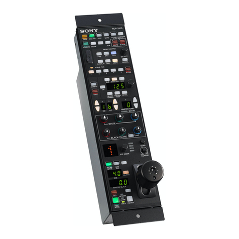
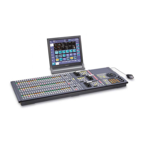
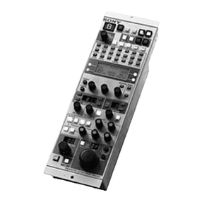
Sony MKS-8010A User manual

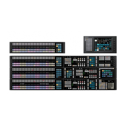
CENTER CONTROL PANEL PACK
CCP-8000
OPERATION MANUAL [English]
2nd Edition (Revised 3)
MKS-8010A MKS-8011A MKS-8013A MKS-8014A
MKS-8015A MKS-8017A MKS-8018A MKS-8019A
MKS-8020A MKS-8021A MKS-8021ASC MKS-8022A
MKS-8022ASC MKS-8023A MKS-8023AB MKS-8024A
MKS-8025MS MKS-8026A MKS-8027A MKS-8028A
MKS-8030A MKS-8031AJS MKS-8031ATB MKS-8032A
MKS-8033A MKS-8034ADK MKS-8034AFB MKS-8035A
MKS-8036A MKS-8040 MKS-8041 MKS-8042
MKS-8075A MKS-8076 HK-PSU02

2
To reduce the risk of fire or electric shock,
do not expose this apparatus to rain or
moisture.
To avoid electrical shock, do not open the
cabinet. Refer servicing to qualified
personnel only.
THIS APPARATUS MUST BE EARTHED.
For the customers in the USA
This equipment has been tested and found to comply with the
limits for a Class A digital device, pursuant to Part 15 of the
FCC Rules. These limits are designed to provide reasonable
protection against harmful interference when the equipment is
operated in a commercial environment. This equipment
generates, uses, and can radiate radio frequency energy and,
if not installed and used in accordance with the instruction
manual, may cause harmful interference to radio
communications. Operation of this equipment in a residential
area is likely to cause harmful interference in which case the
user will be required to correct the interference at his own
expense.
You are cautioned that any changes or modifications not
expressly approved in this manual could void your authority to
operate this equipment.
(Except for HK-PSU02)
All interface cables used to connect peripherals must be
shielded in order to comply with the limits for a digital device
pursuant to Subpart B of Part 15 of FCC Rules.
(HK-PSU02 only)
This device complies with Part 15 of the FCC Rules.
Operation is subject to the following two conditions: (1) this
device may not cause harmful interference, and (2) this device
must accept any interference received, including interference
that may cause undesired operation.
For the customers in Canada (HK-PSU02 only)
This Class A digital apparatus complies with Canadian ICES-
003.
Pour les utilisateurs au Canada (HK-PSU02 uniquement)
Cet appareil numérique de la classe A est conforme à la
norme NMB-003 du Canada.
This symbol is intended to alert the user to the
presence of important operrating and
maintenance (servicing) instructions in the
literature accompanying the appliance.
WARNING: THIS WARNING IS APPLICABLE FOR USA
ONLY.
If used in USA, use the UL LISTED power cord specified
below.
DO NOT USE ANY OTHER POWER CORD.
Plug Cap Parallel blade with ground pin
(NEMA 5-15P Configuration)
Cord Type SJT, three 16 or 18 AWG wires
Length Minimum 1.5 m (4 ft 11 in), Less than 2.5 m
(8 ft 3 in)
Rating Minimum 10 A, 125 V
Using this unit at a voltage other than 120 V may require the
use of a different line cord or attachment plug, or both. To
reduce the risk of fire or electric shock, refer servicing to
qualified service personnel.
WARNING: THIS WARNING IS APPLICABLE FOR OTHER
COUNTRIES.
1.Use the approved Power Cord (3-core mains lead) /
Appliance Connector / Plug with earthing-contacts that
conforms to the safety regulations of each country if
applicable.
2.Use the Power Cord (3-core mains lead) / Appliance
Connector / Plug conforming to the proper ratings (Voltage,
Ampere).
If you have questions on the use of the above Power Cord /
Appliance Connector / Plug, please consult a qualified service
personnel.
WARNUNG: DIESE WARNUNG GILT FÜR ANDERE
LÄNDER.
1.Verwenden Sie Netzkabel (dreiadrig), Geräteanschlüsse
und Netzkabelstecker mit Masseleitung, die den
Sicherheitsrichtlinien des jeweiligen Landes entspricht.
2.Verwenden Sie Netzkabel (dreiadrig), Geräteanschlüsse
und Netzkabelstecker mit Masseleitung, die den vor Ort
herrschenden Spannungsanforderungen (Spannung,
Stromstärke) entsprechen.
Bei Frage über die Eignung und Sicherheit von Netzkabeln
(dreiadrig), Geräteanschlüssen und Netzkabelsteckern
wenden Sie sich bitte an einen qualifizierten Elektrotechniker.
AVERTISSEMENT: CET AVERTISSEMENT EST VALABLE
POUR LES AUTRES PAYS.
1.Utiliser un cordon d’alimentation approuvé (conducteur
d’alimentation 3 âmes)/connecteur d’appareil/prise avec
contacts de mise à la terre conforme aux règles de sécurité
de chaque pays si applicable.
2.Utiliser un cordon d’alimentation approuvé (conducteur
d’alimentation 3 âmes)/connecteur d’appareil/prise
conforme aux valeurs nominales (tension, ampérage)
correctes.
S’adresser à un personnel de service qualifié pour toute
question concernant l’emploi du cordon d’alimentation/
connecteur d’appareil/prise ci-dessus.
WARNING

3
Um die Gefahr von Bränden oder
elektrischen Schlägen zu verringern, darf
dieses Gerät nicht Regen oder Feuchtigkeit
ausgesetzt werden.
Um einen elektrischen Schlag zu
vermeiden, darf das Gehäuse nicht
geöffnet werden. Überlassen Sie
Wartungsarbeiten stets nur qualifiziertem
Fachpersonal.
DIESES GERÄT MUSS GEERDET
WERDEN.
Afin de réduire les risques d’incendie ou
d’électrocution, ne pas exposer cet
appareil à la pluie ou à l’humidité.
Afin d’écarter tout risque d’électrocution,
garder le coffret fermé. Ne confier
l’entretien de l’appareil qu’à un personnel
qualifié.
CET APPAREIL DOIT ÊTRE RELIÉ À LA
TERRE.
For the customers in Europe (MKS-8010A only)
This product with the CE marking complies with both the EMC
Directive (89/336/EEC) and the Low Voltage Directive (73/23/
EEC) issued by the Commission of the European Community.
Compliance with these directives implies conformity to the
following European standards:
• EN60950-1: Product Safety
• EN55103-1: Electromagnetic Interference (Emission)
• EN55103-2: Electromagnetic Susceptibility (Immunity)
This product is intended for use in the following
Electromagnetic Environment: E4 (controlled EMC
environment, ex. TV studio).
Für Kunden in Europa (nur MKS-8010A)
Dieses Produkt besitzt die CE-Kennzeichnung und erfüllt die
EMV-Richtlinie (89/336/EWG) sowie die
Niederspannungsrichtlinie (73/23/EWG) der EG-Kommission.
Angewandte Normen:
• EN60950-1: Sicherheitsbestimmungen
• EN55103-1: Elektromagnetische Verträglichkeit
(Störaussendung)
• EN55103-2: Elektromagnetische Verträglichkeit
(Störfestigkeit),
für die folgenden elektromagnetischen Umgebungen: E4
(kontrollierter EMV-Bereich, z.B. Fernsehstudio)
Pour les clients européens (MKS-8010A uniquement)
Ce produit portant la marque CE est conforme à la fois à la
Directive sur la compatibilité électromagnétique (EMC) (89/
336/CEE) et à la Directive sur les basses tensions (73/23/
CEE) émises par la Commission de la Communauté
européenne.
La conformité à ces directives implique la conformité aux
normes européennes suivantes:
• EN60950-1: Sécurité des produits
• EN55103-1: Interférences électromagnétiques (émission)
• EN55103-2: Sensibilité électromagnétique (immunité)
Ce produit est prévu pour être utilisé dans l’environnement
électromagnétique suivant: E4 (environnement EMC contrôlé
ex. studio de télévision).
For the customers in Europe (MKS-8011A/8013A/8014A/
8015A/8017A/8018A/8019A/8020A/8021A/8021ASC/
8022A/8022ASC/8023A/8023AB/8024A/8025MS/8026A/
8027A/8028A/8030A/8031AJS/8031ATB/8032A/8033A/
8034ADK/8034AFB/8035A/8036A/8040/8041/8075A/8076
only)
This product with the CE marking complies with the EMC
Directive (89/336/EEC) issued by the Commission of the
European Community.
Compliance with this directive implies conformity to the
following European standards:
• EN55103-1: Electromagnetic Interference (Emission)
• EN55103-2: Electromagnetic Susceptibility (Immunity)
This product is intended for use in the following
Electromagnetic Environment: E4 (controlled EMC
environment, ex. TV studio).
Für Kunden in Europa (nur MKS-8011A/8013A/8014A/
8015A/8017A/8018A/8019A/8020A/8021A/8021ASC/
8022A/8022ASC/8023A/8023AB/8024A/8025MS/8026A/
8027A/8028A/8030A/8031AJS/8031ATB/8032A/8033A/
8034ADK/8034AFB/8035A/8036A/8040/8041/8075A/8076)
Dieses Produkt besitzt die CE-Kennzeichnung und erfüllt die
EMV-Richtlinie (89/336/EWG) der EG-Kommission.
Angewandte Normen:
• EN55103-1: Elektromagnetische Verträglichkeit
(Störaussendung)
• EN55103-2: Elektromagnetische Verträglichkeit
(Störfestigkeit),
für die folgenden elektromagnetischen Umgebungen: E4
(kontrollierter EMV-Bereich, z.B. Fernsehstudio).
Pour les clients européens (MKS-8011A/8013A/8014A/
8015A/8017A/8018A/8019A/8020A/8021A/8021ASC/
8022A/8022ASC/8023A/8023AB/8024A/8025MS/8026A/
8027A/8028A/8030A/8031AJS/8031ATB/8032A/8033A/
8034ADK/8034AFB/8035A/8036A/8040/8041/8075A/8076
uniquement)
Ce produit portant la marque CE est conforme à la Directive
sur la compatibilité électromagnétique (EMC) (89/336/CEE)
émise par la Commission de la Communauté européenne.
La conformité à cette directive implique la conformité aux
normes européennes suivantes:
• EN55103-1: Interférences électromagnétiques (émission)
WARNUNG
AVERTISSEMENT

4
• EN55103-2: Sensibilité électromagnétique (immunité)
Ce produit est prévu pour être utilisé dans l’environnement
électromagnétique suivant: E4 (environnement EMC contrôlé
ex. studio de télévision).
For the customers in Europe (HK-PSU02 only)
This product with the CE marking complies with the EMC
Directive (89/336/EEC) issued by the Commission of the
European Community.
Compliance with this directive implies conformity to the
following European standards:
• EN55103-1: Electromagnetic Interference (Emission)
• EN55103-2: Electromagnetic Susceptibility (Immunity)
This product is intended for use in the following
Electromagnetic Environment(s):
E1 (residential), E2 (commercial and light industrial), E3
(urban outdoors) and E4 (controlled EMC environment, ex.
TV studio).
Für Kunden in Europa (nur HK-PSU02)
Dieses Produkt besitzt die CE-Kennzeichnung und erfüllt die
EMV-Richtlinie (89/336/EWG) der EG-Kommission.
Angewandte Normen:
• EN55103-1: Elektromagnetische Verträglichkeit
(Störaussendung)
• EN55103-2: Elektromagnetische Verträglichkeit
(Störfestigkeit),
für die folgenden elektromagnetischen Umgebungen:
E1 (Wohnbereich), E2 (kommerzieller und in beschränktem
Maße industrieller Bereich), E3 (Stadtbereich im Freien) und
E4 (kontrollierter EMV-Bereich, z.B. Fernsehstudio).
Pour les clients européens (HK-PSU02 seulement)
Ce produit portant la marque CE est conforme à la Directive
sur la compatibilité électromagnétique (EMC) (89/336/CEE)
émise par la Commission de la Communauté européenne.
La conformité à cette directive implique la conformité aux
normes européennes suivantes:
• EN55103-1: Interférences électromagnétiques (émission)
• EN55103-2: Sensibilité électromagnétique (immunité)
Ce produit est prévu pour être utilisé dans les
environnements électromagnétiques suivants:
E1 (résidentiel), E2 (commercial et industrie légère),
E3 (urbain extérieur) et E4 (environnement EMC contrôlé,
ex. studio de télévision).
Periodic inspections
To guarantee safe long-term operation, periodic inspections
are recommended. Please contact your Sony representative
for detailed information about the content and cost of periodic
inspections.
Für Kunden in Deutschland (nur MKS-8010A)
Wenn Sie das Gerät entsorgen wollen, wenden Sie sich bitte
an das nächste Sony-Kundendienstzentrum. Der eingebaute
Akku muß als chemischer Sondermüll entsorgt werden.
For Customers in Taiwan only (MKS-8010A only)
For the customers in the USA (MKS-8011A only)
This product (fluorescent lamp in the liquid crystal display)
contains mercury. Disposal of this product may be regulated if
sold in the United States. For disposal or recycling information,
please contact your local authorities or the Electronics
Industries Alliance (www.eiae.org http://www.eiae.org)
For the State of California, USA only (MKS-8010A only)
Perchlorate Material - special handling may apply, See
www.dtsc.ca.gov/hazardouswaste/perchlorate
Perchlorate Material : Lithium battery contains perchlorate.

5
Table of Contents
Table of Contents
Overview ............................................................................... 7
Features......................................................................................7
Units and Modules.....................................................................7
Optional Accessories .................................................................9
Location and Function of Parts......................................... 10
MKS-8010A Front Panel........................................................ 10
MKS-8010A Rear Panel ......................................................... 11
MKS-8011A Menu Panel ....................................................... 13
Main Panel .............................................................................. 13
AUX Panel.............................................................................. 14
MKS-8025MS “Memory Stick”/USB Module....................... 14
MKS-8075A Extension Adaptor ............................................ 15
MKS-8076 Memory Card/USB Adaptor................................ 15
Example System Configuration ........................................ 16
MVS-8000A System Configuration ....................................... 16
Center Control Panel Connection ........................................... 17
Exchanging Button Labels ................................................ 18
Adjusting Fader Torque..................................................... 19
Power Supply Unit Status Indicators................................19
Care of the Control Panel ..................................................20
About a “Memory Stick” .................................................... 20
What Is “Memory Stick”? .......................................................20
Types of “Memory Stick”........................................................20
Available Types of “Memory Stick” .......................................21
Note on “Memory Stick PRO” ................................................21
Notes on “Memory Stick Duo”................................................21
Before Using a “Memory Stick”..............................................21
About Formatting “Memory Stick” .........................................21
Caution When Formatting “Memory Stick” on a Personal
Computer........................................................................22
When the Status Indicator Is Lit or Flashing ...........................22
Precautions...............................................................................22
Specifications ..................................................................... 22
Center Control Panel................................................................22
Main Panel ............................................................................... 22
AUX panel ...............................................................................23
MKS-8010A System Control Unit ..........................................23
MKS-8011A Menu Panel ........................................................24
MKS-8013A 32 AUX Bus Module .........................................24
MKS-8014A 24 AUX Bus Module .........................................24
MKS-8015A 16 AUX Bus Module .........................................24
MKS-8017A 32 XPT Module .................................................25

6Table of Contents
MKS-8018A 24 XPT Module .................................................25
MKS-8019A 16 XPT Module .................................................25
MKS-8020A Standard Transition Module ..............................25
MKS-8021A Simple Transition Right Module .......................25
MKS-8021ASC Simple Transition Compact Right Module...25
MKS-8022A Simple Transition Left Module..........................25
MKS-8022ASC Simple Transition Compact Left Module .....26
MKS-8023A Compact Key Transition Module ......................26
MKS-8023AB Compact Key Transition Module.................... 26
MKS-8024A Flexi Pad Module...............................................26
MKS-8025MS “Memory Stick”/USB Module........................26
MKS-8026A 10 Key Pad Module ...........................................26
MKS-8027A Compact Transition Right Module ....................26
MKS-8028A Compact Transition Left Module ......................27
MKS-8030A Key Frame Module ............................................27
MKS-8031AJS Joystick Module .............................................27
MKS-8031ATB Track Ball Module........................................27
MKS-8032A DSK Fader Module............................................27
MKS-8033A Utility/Shotbox Module .....................................27
MKS-8034ADK DSK/FTB Module........................................27
MKS-8034AFB FTB Module..................................................27
MKS-8035A Key Control Module ..........................................28
MKS-8036A Device Control Module .....................................28
MKS-8040 Blank Panel (1/3) ..................................................28
MKS-8041 Blank Panel (1/2) ..................................................28
MKS-8042 Blank Panel (1/6) ..................................................28
MKS-8075A Extension Adaptor .............................................28
MKS-8076 Memory Card/USB Adaptor.................................29
HK-PSU02 Power Supply Unit ...............................................29

7
Overview
Overview
The CCP-8000 Center Control Panel Pack provides
control panels for operation of a MVS-8000 Multi Format
Switcher system. It has a wide range of application, being
usable in studios and the ENG and OB vans of large-scale
live production systems as well as in postproduction
editing systems.
“Center control panel” refers to the control panel as a
whole, which is comprised of the following three elements.
Main Panel
The main panel, comprised of various types of operation
modules, provides the operating controls of the system. It
can be freely laid out, with variable numbers of M/E banks
(2 to 4) and cross-point buttons (24 or 32) and variable
layout of the auxiliary bus module. Operation modules can
be mounted in the MKS-8075A Extension Adaptor and
MKS-8076 Memory Card/USB Adaptor for installation
apart from the main panel. The auxiliary bus module can
also be removed from the main panel and used as an AUX
panel.
Menu Panel
The menu panel provides a GUI interface for making
system settings.
System Control Unit
The system control unit provides control functions for the
center control panel as a whole. It also supplies power to
the various panels.
Features
Free control panel layout
The modular configuration of the center control panel
allows operation modules to be freely laid out in the way
that best meets your requirements.
Intuitive, easy-to-use man-machine
interface
The Flexi PadTM and shotbox sections feature LCD display
buttons that can display the names of registered effects or
graphics for registered patterns. Registered effects are
evident at a glance, a significant advantage in live
situations where decisions must be made instantly. The
menu control block features a large, touch-sensitive LCD
panel for speedy menu operations.
Special features for mid- and large-scale
live switcher systems
The center control panel was designed with many features
for live operation, such as shotbox functions, source name
display on cross-point buttons, the ability to recall
snapshots and other effect memory settings directly on the
Flexi PadTM, and redundant power supply.
Powerful external device control
The center control panel can control devices such as Sony
routing switchers and IF processors. Control of devices
such as VTRs and DDRs can be linked to timelines of
switchers and DME.
Generous storage capacity
The center control panel has an internal hard disk drive for
storage of settings and still pictures from switcher frame
memory. They can also be storage to “Memory Sticks” and
other memory cards.
Units and Modules
MKS-8010A System Control Unit
A system control unit to provide control functions for the
center control panel as a whole and supply power to the
various panels.
MKS-8011A Menu Panel
A menu operation panel equipped with a 10.4-inch color
LCD touch screen.
MKS-8013A 32 AUX Bus Module
An auxiliary bus control module with 32 cross-point
buttons.
MKS-8014A 24 AUX Bus Module
An auxiliary bus control module with 24 cross-point
buttons.
MKS-8015A 16 AUX Bus Module
An auxiliary bus control module with 16 cross-point
buttons.
MKS-8017A 32 XPT Module
An M/E or PGM/PST bank cross-point module with 32
cross-point buttons.

8Overview
MKS-8018A 24 XPT Module
An M/E or PGM/PST bank cross-point module with 24
cross-point buttons.
MKS-8019A 16 XPT Module
An M/E or PGM/PST bank cross-point module with 16
cross-point buttons.
MKS-8020A Standard Transition Module
A transition operation module for an M/E bank or the
PGM/PST bank. Comprised of a transition operation
section and a key transition operation section.
MKS-8021A Simple Transition Right
Module
A transition operation module for an M/E bank or the
PGM/PST bank. Comprised of a transition operation
section with a split fader and a Flexi Pad section. The fader
lever is at a different position than on the MKS-8022A.
MKS-8021ASC Simple Transition Compact
Right Module
A transition operation module for an M/E bank or the
PGM/PST bank. Comprised of a transition operation
section with a split fader and a Flexi Pad section. The fader
lever is at a different position than on the MKS-8022ASC.
MKS-8022A Simple Transition Left Module
A transition operation module for an M/E bank or the
PGM/PST banks. Comprised of a transition operation
section with a split fader and a Flexi Pad section. The fader
lever is at a different position than on the MKS-8021A.
MKS-8022ASC Simple Transition Compact
Left Module
A transition operation module for an M/E bank or the
PGM/PST bank. Comprised of a transition operation
section with a split fader and a Flexi Pad section. The fader
lever is at a different position than on the MKS-8021ASC.
MKS-8023A Compact Key Transition
Module
A key transition operation module for 2-keyer transitions.
Used in combination with the MKS-8021A or MKS-
8022A.
MKS-8023AB Compact Key Transition
Module
A key transition operation module for 2/4-keyer
transitions. Used in combination with the MKS-8021A/
8021ASC/8022A/8022ASC.
MKS-8024A Flexi Pad Module
An operation module for Flexi Pad operations. Used in
combination with the MKS-8020A.
MKS-8025MS “Memory Stick”/USB Module
A module equipped with a “Memory Stick” slot and three
DEVICE connectors.
MKS-8026A 10 Key Pad Module
A numeric keypad module.
MKS-8027A Compact Transition Right
Module
A transition operation module for an M/E bank or the
PGM/PST bank. Features a simple key transition operation
section. A compact module that fits in 1/2 rack width.
MKS-8028A Compact Transition Left
Module
Identical to the MKS-8027A, but with the fader lever on
the left side.
MKS-8030A Key Frame Module
A module for key frame operations.
MKS-8031AJS Joystick Module
A module for DME operations using a joystick and for
switcher wipe positioner operations.
MKS-8031ATB Track Ball Module
A module for DME operations using a track ball and for
switcher wipe positioner operations.
MKS-8032A DSK Fader Module
An operation module for fader lever operations on four
downstream keys.
MKS-8033A Utility/Shotbox Module
An operation module to provide buttons that may be used
as utility buttons or shotbox recall buttons.

9
Overview
MKS-8034ADK DSK/FTB Module
An operation module for operations on two downstream
keys and for fade to black and preview selector operations.
(This module is the MKS-8034AFB module with the
addition of controls for DSK operations.)
MKS-8034AFB FTB Module
An operation module for fade to black and preview
selector operations.
MKS-8035A Key Control Module
An operation module for key adjustments and other
operations.
MKS-8036A Device Control Module
An operation module for disk recorder/VTR control
operations.
MKS-8040 Blank Panel (1/3)
A blank panel to fill parts of the main panel which are not
filled by the modules in its current configuration.
MKS-8041 Blank Panel (1/2)
A blank panel to fill parts of the main panel which are not
filled by the modules in its current configuration.
MKS-8042 Blank Panel (1/6)
A blank panel to fill parts of the main panel which are not
filled by the modules in its current configuration.
MKS-8075A Extension Adaptor
An adaptor which allows modules to be installed apart
from the main panel.
MKS-8076 Memory Card/USB Adaptor
An adaptor that allows the MKS-8025MS to be installed
apart from the main panel.
HK-PSU02 Power Supply Unit (on MKS-
8010A)
A backup power supply unit. The MKS-8010A is supplied
standard with one power unit. Installing an HK-PSU02
gives two power units.
This allows a backup system to be constructed which will
operate normally even if one of the power supply units
fails.
Optional Accessories
SWC-5002 50-pin Panel Cable (2 m/7 ft)
SWC-5005 50-pin Panel Cable (5 m/16 ft)
SWC-5010 50-pin Panel Cable (10 m/33 ft)
RMM-10 Rack Mount Kit

10 Location and Function of Parts
Location and Function of Parts
MKS-8010A Front Panel
POWER A and B switches and status indicators
The POWER switches turn the unit on and off. The unit is
powered on when the POWER switches are on the “?” side,
and powered off when the POWER switches are on the
“a” side. The status indicators light in green when the unit
is powered on.
Depending on the configuration of your unit, an optional
Backup Power Supply Unit may not be installed. In this
case, there is no POWER B switch indicator.
Caution
Before installing an optional Backup Power Supply Unit in
your unit, be sure to contact your Sony service
representative.
Note
If a status indicator does not light when you turn a POWER
switch on, there may be a fault in the power circuits. Turn
the POWER switch off and contact your Sony service
representative.
POWER A POWER B
POWER A switch and status indicator
POWER B switch and status indicator

11
Location and Function of Parts
MKS-8010A Rear Panel
aREMOTE connector (BNC type)
Connect this connector with a BNC cable to an S-BUS data
link via a T bridge.
An S-BUS data link is a single signaling circuit (S-BUS)
to which multiple devices can be connected to exchange
data.
Connecting devices such as HDS-X3000 series routing
switchers and remote panels to an S-BUS data link enables
the following kinds of control.
• Returning to the S-BUS, tally data created by this unit on
the basis of data received from other devices
• Switching the cross-points of a routing switcher from the
center control panel
• Switching the cross-points of a switcher from the remote
panel
• Displaying on the center control panel source names set
on a routing switcher
bREF IN (reference signal input) connectors
(BNC type)
If you wish to synchronize this unit to an external reference
signal, input the reference signal. For an HDTV system,
input an HD tri-level sync signal, black burst signal, or
analog sync signal. For an SDTV system, input a black
burst signal or analog sync signal.
The two connectors have a loop-through configuration.
Signal input to one connector can be output from the other
connector. If you will not be using the loop-through
output, be sure to terminate the unused connector with the
supplied 75Ωterminator.
cEXT (extension) PANEL 1 to 3 connectors
(D-sub 50-pin, special interface)
Connect to the MKS-8075A Extension Adaptors and AUX
panels to install operation modules apart from the center
control panel.
dGPI (General Purpose Interface) connector
(D-sub 25-pin)
Connect to external devices for input and output of trigger
signals. Up to eight inputs and eight outputs are possible,
with input and output conditions set on the center control
panel.
eLTC IN (longitudinal timecode input) connector
(BNC type)
Connect to a timecode generator.
f- AC IN (AC power input) A and B connectors
(3-pin)
Connect to 100 to 240 V AC power supply with the
optional AC power cords.
Depending on the configuration of your unit, the Backup
Power Supply Unit may not be installed. In that case, the
AC IN B connector is not used.
MENU PANEL EXT PANEL1 EXT PANEL2 EXT PANEL3 MAIN PANEL
EXT DISPLAY
-AC IN
UBA
CTRLEDITOR PANEL PERIPHREF IN REMOTE LTC IN GPIDATA DEVICE
qgMENU PANEL connector
3EXT PANEL 1 to 3 connectors
qsMAIN PANEL connector
6-AC IN A and B connectors
7Uterminal
4GPI connector
5LTC IN connector
9PERIPH connector
qdCTRL connector
1REMOTE connector
2REF IN connectors
8EDITOR PANEL connector
q;DEVICE connector
qaDATA connector
qfEXT DISPLAY connector

12 Location and Function of Parts
Caution
For information about installing, contact your Sony
service representative.
gU(signal ground) terminal
Connect to the system ground.
hEDITOR PANEL connector (D-sub 15-pin, RS-
422A)
This connector is reserved for future system expansion.
iPERIPH (peripheral) connector (RJ-45)
Connect to the DCU-8000 Device Control Unit Pack with
a cross cable to enable communications with the DCU-
8000.
Note
An Ethernet switch is required to connect two or more
DCU-8000 Device Control Units.
jDEVICE connector (USB Type A)
Connect to the HOST connector of the main panel, AUX
panel or the MKS-8076 Memory Card/USB Adaptor.
kDATA connector (RJ-45)
Connect to an Ethernet switch.*
The MVS-8000A/8000ASF Switcher Processor, the
MVE-8000A DME Processor and other devices can be
connected in the same way to the Ethernet switch to form
a network for exchange of signals between the devices.
This network is used primarily for exchange of various
types of data (key frame effects, snapshots, etc.) and still
pictures of frame memory.
* Ethernet is a trademark of XEROX Corporation.
For information about Ethernet switches that can be used in an MVS
system, contact your Sony service representative.
For detailed information about setting up the Ethernet
switch, refer to the documentation supplied with the
Ethernet switch.
lMAIN PANEL connector (D-sub 50-pin,
special interface)
Connect to the SCU connector of the main panel.
mCTRL (control) connector (RJ-45)
Connect to an Ethernet switch.
The MVS-8000A/8000ASF Switcher Processor, the
MVE-8000A DME Processor and other devices are
connected in the same way to the Ethernet switch to form
a network for exchange of signals between the devices.
This network is used primarily to control the various
devices from the center control panel.
nEXT (extension) DISPLAY connector
(high-density D-sub 15-pin, analog RGB)
This connector is reserved for future system expansion.
oMENU PANEL connector (D-sub 50-pin,
special interface)
Connect to the menu panel.
Caution
• For safety, do not connect the connector for peripheral
device wiring that might have excessive voltage to the
following ports.
- PERIPH (peripheral) connector
- DATA connector
- CTRL (control) connector
Follow the instructions for the above ports.
• When you connect the LAN cable of the unit to
peripheral device, use a shielded-type cable to prevent
malfunction due to radiation noise.

13
Location and Function of Parts
MKS-8011A Menu Panel
SCU (system control unit) connector (D-sub 50-pin,
special interface)
Connect to the MENU PANEL connector of the MKS-
8010A System Control Unit.
Main Panel
aSCU (system control unit) connector (D-sub 50-pin,
special interface)
Connect to the MAIN PANEL connector of the MKS-
8010A System Control Unit.
bHOST connector (USB Type B)
Connect to the DEVICE connector of the MKS-8010A
System Control Unit.
cDEVICE connectors (USB Type A)
Connect to external devices with USB connectors.
For connectable devices, contact your Sony service
representative.
SCU connector
HOSTDEVICE SCU
1SCU connector
2HOST connector
3DEVICE connectors

14 Location and Function of Parts
AUX Panel
aSCU (system control unit) connector (D-sub 50-pin,
special interface)
Connect to one of the EXT PANEL 1 to 3 connectors of the
MKS-8010A System Control Unit.
bHOST connector (USB Type B)
Connect to the DEVICE connector of the MKS-8010A
System Control Unit.
cDEVICE connectors (USB Type A)
Connect to external devices with USB connectors.
For connectable devices, contact your Sony service
representative.
MKS-8025MS “Memory Stick”/USB Module
aStatus indicator
Data is being read from or written to a “Memory Stick”
when the status indicator is lit or flashing.
Note
Do not power the unit off or remove a “Memory Stick”
when the status indicator is lit or flashing.
b“Memory Stick” slot
A slot to insert “Memory Sticks.”
See “About a “Memory Stick”” (page 20) for more
information about “Memory Sticks.”
HOSTDEVICE SCU
1SCU connector
2HOST connector
3DEVICE connectors
1Status indicator
2“Memory Stick” slot
3DEVICE connectors

15
Location and Function of Parts
cDEVICE connectors (USB Type A)
Connect to external devices with USB connectors.
For connectable devices, contact your Sony service
representative.
MKS-8075A Extension Adaptor
aSCU IN (system control unit input) connector
(D-sub 50-pin, special interface)
Connect to one of the EXT PANEL 1 to 3 connectors of the
MKS-8010A System Control Unit or to the SCU OUT
connector of the MKS-8075A.
bSCU OUT (system control unit output) connector
(D-sub 50-pin, special interface)
Connect to the SCU IN connector of the MKS-8075A.
MKS-8076 Memory Card/USB Adaptor
HOST connector (USB Type B)
Connect to the DEVICE connector of the MKS-8010A
System Control Unit.
OUT
IN
1SCU IN connector 2SCU OUT connector
OUT
IN
HOST connector

16 Example System Configuration
Example System Configuration
MVS-8000A System Configuration
CTRL
CTRL
DATA
REMOTE
EDITOR PANEL
REMOTE
DATA CTRL DATA
PERIPH
PERIPH
Reference video signal b)
MKS-8050/2050
Editing Key Board c)
Ethernet switch a)
MVE-8000A DME Processor
MKS-8010A System
Control Unit
BKS-R Series
Reference
video signal b)
Reference video
signal b)
Cross cable
Cable with BNC connectors
MVS-8000ASF Switcher
Processor
Ethernet switch a)
VTR DDR Audio Mixer
Reference video signal b)
DCU-2000-C Device
Control Unit Pack
a) It is recommended that the CTRL and DATA LAN networks be
configured by connecting separate Ethernet switches for each
LAN.
However, it is also possible to make connections for both LANs
on a single Ethernet switch.
b) Terminate with the supplied 75Ωterminators.
Terminators are supplied in the product package.
c) The figure shows the MKS-8050.
d) Dedicated 15-pin cable supplied with the MKS-8050/2050.
15-pin cable
HDS-X Series
d)

17
Example System Configuration
Center Control Panel Connection
MENU PANEL
SCU IN
SCU IN
SCU OUT
SCU IN
SCU OUT
MAIN PANEL
EXT PANEL 3
HOST
HOST HOST
SCU
EXT PANEL 2
SCU
DEVICE a)
SCU
Main Panel
MKS-8075A Extension Adaptor
Reference video signal
MKS-8010A
System Control Unit
MKS-8076 Memory Card/
USB Adaptor
MKS-8011A Menu
Panel
a) There are three ways to install an MKS-8025MS “Memory Stick”/
USB Module.
•To install it in the main panel, connect the DEVICE connector on
the MKS-8010A and the HOST connector on the main panel.
•To install it on the AUX panel, connect the DEVICE connector on
the MKS-8010A and the HOST connector on the AUX panel.
•To install it apart from the main panel using an MKS-8076
adaptor, connect the DEVICE connector on the MKS-8010A and
the HOST connector on the MKS-8076.
Maximum cable length: 5m (16 ft)
b) Maximum cable length: 10 m (33 ft)
b)
a)
100 to 240 V AC power supply
b) a) b)
AUX Panel
a)
b)
b)
b)

18 Exchanging Button Labels
The number of modules that can be connected to a single
MKS-8010A System Control Unit is as follows.
(The maximum number of adaptors that can be connected
on 1 channel is 8.)
However, it is not possible to connect four Key Control
Modules and a 10 Key Pad Module on one channel.
You can also connect a keyboard, mouse, pen tablet and
other devices with USB connectors to the DEVICE
connectors of the main panel regardless of whether an
MKS-8025MS has been installed in the main panel or
installed apart from the main panel using an MKS-8076
adaptor, or to the DEVICE connectors of a module to
operate the MKS-8025MS.
Contact your Sony service representative for more
information about connectable devices.
Note
To make connections to the EXT PANEL 1, 2 and 3
connectors, MAIN PANEL connector, and MENU
PANEL connector on the MKS-8010A System Control
Unit, always use the cables supplied in the package, or
SWC-5005 or SWC-5010 cables.
Exchanging Button
Labels
A button top puller is supplied with the center control
panel.
After changing a pattern assigned to a numeric button, you
can use the following procedure to exchange the button
label.
1
Write the new pattern on one of the supplied exchange
labels.
2
Grip the holes on the button sides with the supplied
button top puller and remove the button.
3
Grip the slots on the sides of the white button cap with
the button top puller, so that the cap flexes slightly,
and remove the cap.
4
Remove the old label and insert the new label.
5
Replace the button cap.
6
Replace the button in its original location.
Model Module name Max. modules
MKS-8013A/
8014A/8015A 32, 24, 16 AUX Bus
Module 2
MKS-8026A 10 Key Pad Module 1
MKS-8030A Key Frame Module 1
MKS-8031AJS Joystick Module 1
MKS-8031ATB Track Ball Module 1
MKS-8033A Utility/Shotbox Module 2
MKS-8035A Key Control Module 4
MKS-8032A DSK Fader Module 4
MKS-8036A Device Control Module 1
23

19
Adjusting Fader Torque / Power Supply Unit Status Indicators
Adjusting Fader Torque
You can adjust faders without removing them from the
center control panel or operation modules (Single fader
only).
Proceed as follows to adjust faders.
1
Pull the fader lever to an upright position between the
two holes on the fader cover.
2
Insert a hexagonal screwdriver or a hexagonal wrench
(4 mm sides) into one or both of the holes and rotate
to adjust the torque.
Rotate clockwise:
Fader lever operation becomes firmer.
Rotate counterclockwise:
Fader lever operation becomes freer.
Note
For a split fader, you cannot make adjustment from the
control panel surface. To make adjustment, it is necessary
to use the two holes provided in the back side of the
module.
If you want split fader torque to be adjusted, consult your
Sony service representative.
Single fader modules
MKS-8020A Standard Transition Module
MKS-8030A Key Frame Module
MKS-8032A DSK Fader Module
MKS-8027A Compact Transition Right Module
MKS-8028A Compact Transition Left Module
Split fader modules
MKS-8021A Simple Transition Right Module
MKS-8022A Simple Transition Left Module
MKS-8021ASC Simple Transition Compact Right
Module
MKS-8022ASC Simple Transition Compact Left Module
Power Supply Unit Status
Indicators
The power supply unit status indicators show the status of
the power supply unit during operation and when the unit
is powered on. Whenever a power error is detected, it is
reflected immediately by the indicator.
Hexagonal wrench
Fader lever
Meaning of status indicator displays
Indicator
color Status Description Steps to take
Green Lit Operating normally −
Red LIt Power supply unit fan
fault Exchange the
fan unit
−Not lit Power supply unit
fault Exchange the
power supply
unit

20 Care of the Control Panel / About a “Memory Stick”
Care of the Control Panel
Clean the control panel unit, switches, and fader levers, by
gently wiping with a soft dry cloth.
In the event of excessive grime, moisten the cloth with a
little cold or lukewarm water, and wipe gently.
Note
Wring out all surplus water from the cloth before use, to
prevent any surplus water from penetrating the panel.
Moisture inside the panel can cause it to fail.
Never use organic solvents, cleaners, or other chemicals.
Do not wipe with excessive force, as this may scratch the
panel.
About a “Memory Stick”
What Is “Memory Stick”?
“Memory Stick” is a new compact, portable and versatile
IC (Integrated Circuit) recording medium with a data
capacity that exceeds a floppy disk.
“Memory Stick” is specially designed for exchanging and
sharing digital data among “Memory Stick” compatible
products. Because it is removable, “Memory Stick” can
also be used for external data storage.
“Memory Stick” is available in two sizes: standard size
and compact “Memory Stick Duo” size. Once attached to
a Memory Stick Duo adapter, “Memory Stick Duo” turns
to the same size as standard “Memory Stick” and thus can
be used with products compliant with standard “Memory
Stick.”
Types of “Memory Stick”
“Memory Stick” is available in the following six types to
meet various requirements in functions.
• “Memory Stick-R”
Stored data are not overwritten. You can write data to
“Memory Stick-R” with “Memory Stick-R” compatible
products only. Copyright protected data that requires
MagicGate copyright protection technology cannot be
written to “Memory Stick-R.”
• “Memory Stick”
Stores any type of data except copyright-protected data
that requires the MagicGate copyright protection
technology.
• “MagicGate Memory Stick”
Equipped with the MagicGate copyright protection
technology.
• “Memory Stick-ROM”
Stores pre-recorded, read-only data. You cannot record on
“Memory Stick-ROM” or erase the pre-recorded data.
• “Memory Stick PRO”
Equipped with the MagicGate copyright protection
technology, designed for use only with equipment
compatible with “Memory Stick PRO.”
Other manuals for MKS-8010A
1
This manual suits for next models
1
Table of contents
Other Sony Control Panel manuals

Sony
Sony RCP-TX7 User manual

Sony
Sony RCP-1001 User manual

Sony
Sony ICP-6520 User manual

Sony
Sony RCP-750 User manual

Sony
Sony BKDS-7025 Instruction Manual

Sony
Sony BKS-R6010 User manual

Sony
Sony BKMA-506 User manual

Sony
Sony ICP-X1116 User manual

Sony
Sony CCP-8000 Series User manual

Sony
Sony DMW-C1 User manual