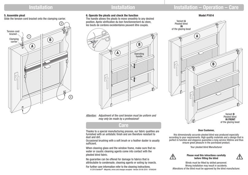
Schenker Storen VSe ZIP Series User manual

Ident. Nr. 60_202 / 17. 04. 2018
VSe ZIP
Typ 2157/2158/2159
Montageanleitung
Instructions de montage
Istruzioni di montaggio
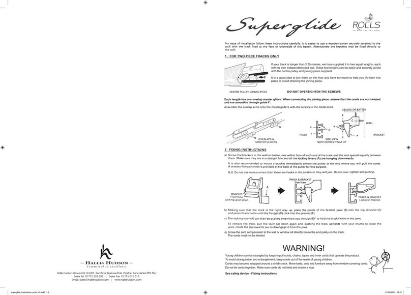
Installation instructions

1Material auf Vollständigkeit kontrollieren / Contrôle d’exhaustivité /
Controllo della completezza / Check material for completeness
DE Die Einbaumasse müssen nach der Montage zwingend
gewährleistet sein, siehe (Fig. 3).
FR Les dimensions d’encastrement doivent impérativement
être garanties après le montage, voir (Fig.3).
IT Le dimensioni devono essere assolutamente
garantite dopo il montaggio. Si veda (Fig. 3).
EN It is essential to check the reference measurements
after assembly, see (Fig. 3).
2Einbaumasse kontrollieren / Contrôle des dimensions d’encastrement /
Controllo dimensioni / Check reference measurements
DE 1. Kasten komplett
2. Stoff
3. Stoffstab
4. Führung einteilig
5. Kunststoff-Innenführung (lang)
6. Kunststoff-Innenführung (kurz)
7. Befestigungsmaterial
8. Wandkonsolen (ZIP eckig)
FR 1. Caisson complet
2. Toile
3. Barre à toile
4. Profil de coulisse en une pièce
5. Guidage intérieur en PVC (long)
6. Guidage intérieur en PVC (court)
7. Matériel de fixation
8. Consoles murale (ZIP angulaire)
IT 1. Cassonetto completo
2. Tessuto
3. Barra finale
4. Profilo per guide in un pezzo
5. Guida interna in plastica (lunga)
6. Guida interna in plastica (corta)
7. Materiale di fissaggio
8. Mensolas a muro (ZIP angolare)
EN 1. Complete blind casing
2. Fabric
3. Fabric rod
4. Guide profile – one piece
5. Plastic inner guide (long)
6. Plastic inner guide (short)
7. Mounting components
8. Wall brackets (angular ZIP)
Typ / Type / Tipo / Model X
VSe110ZIP 2157 ≥ 145 mm
VSe115ZIP 2158 ≥ 165 mm
VSe155ZIP 2159 ≥ 190 mm
VSe110ZIP rund 2157 ≥ 180 mm
VSe115ZIP rund 2158 ≥ 200 mm
Fig. 3
bk/3
X6
34
D1 = D2
bk1 = bk2 ± 2 mm
D1 D2
14,6
bk/3
bk2
bk/3
bk1
DE Führungen links/rechts richtig zuweisen: Symbole beachten, siehe (Fig. 1).
FR Il faut veiller à ce que les profils de coulisse (gauche/droite) soient affectés
correctement (Fig. 1)
IT Prestare attenzione al corretto posizionamento dei profili per guide (sinistra/
destra) (Fig. 1)
EN Make sure that the guide profiles are correctly allocated (left/right), see (Fig. 1).
Fig. 1
Fig. 1
Fig. 2
8
1
3
2
4
5
7
6

3Allgemeine Hinweise zur Montage / Montage en général /
Montaggio generale / General installation information
DE Bestandteile einer Führung siehe (Fig. 4)
1. Aluminium-Führung (fpl)
2. Kunststoff-Innenführung lang (fpl – 38 mm)
3. Kunststoff-Innenführung kurz (50 mm)
4. Vormontiertes Dämpfungsprofil (fpl – 60 mm)
FR Un profil de coulisse se compose de (Fig. 4)
1. Profil de coulisse en aluminium (fpl)
2. Guidage intérieur en PVC long (fpl – 38 mm)
3. Guidage intérieur en PVC court (50 mm)
4. Profil d’insonorisation prémonté (fpl – 60 mm)
IT I profili per guide sono composti da (Fig. 4)
1. Profilo per guide in alluminio (fpl)
2. Profilo per guide in plastica lunga (fpl – 38 mm)
3. Profilo per guide in plastica corta (50 mm)
4. Profilo antirumore premontato (fpl – 60 mm)
EN Components of a guide profile, see (Fig. 4)
1. Aluminium guide profile (fpl)
2. Plastic guide profile long (fpl – 38 mm)
3. Plastic guide profile short (50 mm)
4. Preinstalled noise suppression profile (fpl – 60 mm) Fig. 4
DE Führungen dürfen nicht querbelastet werden (Fig. 5)!
FR Les profils de coulisse ne peuvent pas être sollicités transversalement (Fig. 5)!
IT I profili per guide non devono essere sottoposti a carico trasversale (Fig. 5)!
EN Guide profiles may not be transversely loaded (Fig. 5)!
DE Führungen links/rechts richtig zuweisen: Symbole beachten, siehe Fig. 6.
FR Il faut veiller à ce que les profils de coulisse (gauche/droite) soient affectés correctement: faire
attention aux symboles, voir Fig. 6.
IT Prestare attenzione al corretto posizionamento dei profili per guide (sinistra/destra) (Fig. 6).
EN Make sure that the guide profiles are correctly allocated (left/right), see Fig. 6.
DE Falls Einbaumass X (Kasten plus Länge der Seitendeckel-Lasche) gewährleistet ist (Fig. 3):
Kasten und Führungen getrennt voneinander montieren, siehe Schritt 4.
Vor dem Einsetzen des Kastens auf die Führungen:
a. auf beiden Seiten des Kastens die Schraube an der Seitendeckel-Lasche leicht lösen (Fig. 7).
b. nach dem Einsetzen beide Schrauben wieder festziehen.
FR Si la mesure X (caisson plus longueur du couvercle latéral) est garantie (Fig. 3), le caisson peut
être monté séparément des profils de l’éclisse coulisse (étape 4).
Avant le montage du boîtier sur les profils de coulisses:
a. desserrez légèrement les vis de l’éclisse du couvercle latéral de chaque côté
du caisson (Fig. 7).
b. pour les resserrer après montage.
IT Se la misura X (cassonetto più lunghezza della linguetta della copertura laterale)
è garantita (Fig. 3): montare il cassonetto e le guide separatamente.
Si veda il punto 4.
Prima di applicare il cassone:
a. allentare leggermente la vite sul coperchio laterale (Fig. 7).
b. stringerla di nuovo ad applicazione avvenuta.
EN If measurement X (casing plus the length of the side covers) is assured (Fig. 3):
mount the blind casing and guide profiles separately, see step 4.
Before inserting the box in the guides:
a. on both sides of the box, loosen the screws on the side covers (Fig. 7).
b. then tighten them again after inserting the box.
Fig. 5
Fig. 6
Fig. 7
Fig. 6
1
2
3
4
12
2,5

4Montage getrennt ausführen / Montage séparé /
Montaggio separato / Complete installation separately
6
Stoffstab in Kunststoff-Innenführung (lang) einfädeln / Enfilage de la barre à toile dans le guidage intérieur en PVC (long) /
Montaggio della guida interna in plastica (lungo) / Installing the fabric rod in the plastic inner guide (long)
5Komplettmontage ausführen / Montage complet /
Montaggio completo / Complete the installation
DE a. Store (Kasten plus Führungen) komplett vormontieren, siehe Hinweise unter Schritt 3 a und b.
b. Mindestens 2 Monteure bringen die komplette Store in Position (Fig. 5) und halten sie dort, bis
die Führungen am Gebäude korrekt montiert sind, siehe Fig. 8.
FR a. Prémonter complètement le store (caisson plus profils de coulisses), voir les explications à
l’étape 3 a et b.
b. Au moins 2 installateurs doivent placer tout le store dans sa position (Fig. 5) et le tenir jusqu’à
ce que les profils de coulisses soient correctement fixés au bâtiment, voir Fig. 8.
IT a. La tenda (cassonetto e guide) viene completamente premontata al punto 3 a e b.
b. Almeno due montatori posizionano la tenda completa (Fig. 5) e la sostengono finché le guide non
sono montate correttamente nella struttura. Si veda Fig. 8.
EN a. Completely pre-assemble the blind (box plus guides), see instructions in steps 3 a and b.
b. At least 2 installers must lift the complete blind into position (Fig. 5) and hold it there until the
guides are properly mounted on the building, see Fig. 8.
DE a. Kasten vormontieren.
b. Führungen von unten jeweils in Seitendeckel-Laschen einfahren, siehe Hinweise unter Schritt 3 a, b und Fig. 5.
c. Führungen am Gebäude korrekt montieren (Standardmontage, siehe Fig. 8).
d. Kunststoff-Innenführung einclipsen, siehe Schritt 7.
FR a. Prémonter le caisson.
b. Les profils de coulisses sont ensuite introduits par le bas dans les éclisses du couvercle latéral,
voir les explications à l’étape 3 a, b et Fig. 5.
c. Monter correctement les profils de coulisses au bâtiment (montage standard, voir Fig. 8).
d. Clipper le guidage intérieur en PVC, voir étape 7.
IT a. Il cassonetto viene premontato.
b. Le guide vengono poi inserite dal basso nelle linguette della copertura laterale. Si vedano le indicazioni del punto 3. a, b e Fig. 5.
c. Montaggio della guida (Montaggio standard si veda Fig. 8).
d. Agganciare la guida interna in plastica, si veda il punto 7.
EN a. Preassemble the casing.
b. Insert the guides from below in each of the side cover tabs, see instructions in steps 3 a, b and Fig. 5.
c. Properly mount the guides on the building (standard installation see Fig. 8).
d. Clip the plastic inner guide, see step 7.
DE a. Stoffstab ca. 100 mm absenken und den Reissverschluss in die Kunststoff-Innenführung (lang) auf jeder Seite einfädeln (Fig. 9).
b. Kunststoff-Innenführung jeweils nach oben schieben und so kontrollieren, ob der Stoff sauber in beiden Innenführungen eingefädelt ist.
FR a. Baisser légèrement la barre à toile (env. 100 mm) et enfiler la fermeture à glissière de chaque côté dans le guidage intérieur en PVC (long) (Fig. 9).
b. Pousser vers le haut le guidage intérieur en PVC et contrôler si le tissu est bien enfilé dans les deux guidages intérieurs.
IT a. Abbassare la barra finale di ca. 100 mm e infilare la cerniera nella guida interna in plastica (lunga) in entrambi i lati (Fig. 9).
b. Spingere la guida interna in plastica verso l’alto e in questo modo controllare che la stoffa sia infilata correttamente in entrambe le guide interne.
EN a. Lower the fabric rod approx. 100 mm and thread the zipper in the plastic inner guide (long) on each side (Fig. 9).
b. Push the plastic inner guide upwards and check wether the fabric is properly threaded in both inner guides.
Fig. 8
DE Seitliche Aussparungen der Kunststoff-Innenführung müssen oben sein,
siehe (Fig. 9). Kunststoff-Innenführung einclipsen, siehe Schritt 7.
FR Les dégagements de côté du guidage intérieur en PVC doivent être en
haut (Fig. 9). Clipser le guidage intérieur en PVC, voir étape 7.
IT Le scanalature laterali della guida interna in plastica devono trovarsi in
alto. Si veda la (Fig. 9). Agganciare la guida interna in plastica, si veda
il punto 7.
EN The side recesses of the plastic inner guides must be up (Fig. 9). Clip in
the plastic inner guide, see step 7.
Fig. 9

8Montage Kunststoff-Innenführung (kurz) / Montage du guidage intérieur en PVC (court) /
Montaggio della guida interna in plastica (breve) / Installing the plastic inner guide (short)
7Kunststoff-Innenführung einclipsen / Clipser le guidage intérieur en PVC /
Agganciare la guida interna in plastica / Clip in the plastic inner guide
DE a. Kunststoff-Innenführung am 1. Dämpfungsprofil vorbei in Aluminium-Führung führen (Fig. 10).
Tipp: Zum Einführen der Kunststoff-Innenführung (lang) oben bei der Seitendeckel-Lasche beginnen, wo noch
kein Dämpfungsprofil ist.
b. Kunststoff-Innenführung am 2. Dämpfungsprofil vorbei weiter drücken, bis sie korrekt einclipst (Fig. 11).
c. Kunststoff-Innenführung korrekt über die gesamte Länge der Aluminium-Führung einclipsen.
d. Kontrollieren, ob sich die Kunststoff-Innenführung (lang) leicht nach oben/unten schieben lässt und das Dämpfungs-
profil sauber an der Kunststoff-Innenführung anliegt (Fig. 12).
e. Stoffstab in Kunststoff-Innenführung (lang) einfädeln, siehe Schritt 6.
FR a. Introduire le guidage intérieur en PVC dans la coulisse en aluminium au niveau du 1er profil d’insonorisation (Fig. 10).
Conseil: pour introduire le guidage intérieur en PVC (long) commencer par les éclisses du couvercle latéral où il
n’y a pas encore de profil d’insonorisation.
b. Clipser convenablement le guidage intérieur en PVC sur le 2ème profil d’insonorisation (Fig. 11).
c. Clipser correctement le guidage intérieur en PVC sur toute la longueur de la coulisse en aluminium.
d. Contrôler si le guidage intérieur en PVC (long) peut être légèrement poussé vers le haut ou vers le bas et si le profil
d’insonorisation est bien ajusté au niveau du guidage intérieur en PVC (Fig. 12).
e. Enfilage de la barre à toile dans le guidage intérieur en PVC (long), voir étape 6.
IT a. Agganciare la guida interna in plastica al primo profilo antirumore nella guida in alluminio (Fig. 10).
Consiglio: per inserire la guida interna in plastica (lunga), cominciare in alto dalla linguetta della copertura laterale
dove non c’è ancora nessun profilo antirumore.
b. Spingere ulteriormente la guida interna in plastica sul secondo profilo antirumore finché non si aggancia
correttamente (Fig. 11).
c. Agganciare correttamente la guida interna in plastica nella guida in alluminio per l’intera lunghezza.
d. Controllare che la guida interna in plastica (lunga) possa essere spinta facilmente verso l’alto/il basso e che il profilo
antirumore si trovi correttamente su di essa (Fig. 12).
e. Montaggio della guida interna in plastica (lungo), si veda il punto 6.
EN a. Clip the plastic inner guide into the aluminium guide (Fig. 10).
Tip: To insert the plastic inner guide (long), start above by the side casing where there is not yet any
noise-suppression profile.
b. Clip the plastic inner guide in the 2nd noise-suppression profile until it properly clips in (Fig. 11).
c. Properly clip the plastic inner guide along the entire lenght of the aluminum guide.
d. Check whether the plastic inner guide (long) can be easily pushed up/down and that the noise-suppression profile
properly lies on the plastic inner guide (Fig. 12).
e. Installing the fabric rod in the plastic inner guide (long), see step 6.
DE Kunststoff-Innenführung nicht in die hintere Kammer drücken (Fig. 13).
FR Le guidage intérieur en PVC ne peut pas être poussé dans le creux arrière (Fig. 13)
IT Non spingere la guida interna in plastica nella camera posteriore (Fig. 13)
EN Do not press the plastic inner guide into the rear chamber (Fig. 13)
DE a. Kunststoff-Innenführung (lang) in Führung hoch schieben (Fig. 14) und halten.
b. Kunststoff-Innenführung (kurz) (Fig. 15) unten in Führung entsprechend Schritt 7 einclipsen.
FR a. Pousser vers le haut le guidage intérieur en PVC (Fig. 14) et le tenir ainsi.
b. Clipser le guidage intérieur en PVC (court) juste (Fig. 15) en bas comme à l’étape 7.
IT a. Spingere la guida interna in plastica (lunga) verso l’alto (Fig. 14) e sostenere.
b. Far scattare in basso la guida interna in plastica (corta) (Fig. 15) secondo il punto 7.
EN a. Slide the plastic inner guide (long) lengthways upwards (Fig. 14), and hold it.
b. Clip in the plastic inner guide (short) (Fig. 15) below in the guide as shown in step 7.
Fig. 14
Fig. 10
Fig. 11
Fig. 12
Fig. 13
Fig. 15

9Gegenzuganlage (GZA) montieren (optional) / Monter l’entraînement à contre-traction (GZA) (en option) /
Montaggio dell’azionamento di contromarcia (GZA) (opzionale) / Install the counter-drive system (GZA) (optional)
DE Bei Ausführungen mit Gegenzuganlage (GZA) die Montageschritte 2 bis 11 ausführen. Je nach Einbau-
situation kann die Endschiene auch von unten in die Führungen eingesetzt werden (analog FM 51).
FR Pour les versions avec entraînement à contre-traction (GZA), on effectue les étapes de montage 2 à 11.
En fonction de la situation de montage, la barre finale peut aussi être introduite par le bas dans les coulisses
(par analogie à FM 51).
IT Sulle versioni con azionamento di contromarcia (GZA) vengono eseguite le fasi di montaggio da 2 a 11.
A seconda della situazione di montaggio, la barra finale può essere inserita nelle guide anche dal basso
(simile a FM 51).
EN For designs that have a counter-drive system (GZA), carry out installation steps 2 to 11. Depending on
the installation situation, the end rail can also be inserted in the guide from below (similar to FM 51).
DE a. Endschiene in untere Endlage fahren.
b. Auf einer Seite das Drahtseil durch den Führungsabschluss einfädeln, siehe (Fig. 16).
Drahtseilklemme bündig an Führungsabschluss schieben.
c. Innensechskant-Schrauben festziehen.
d. Auf der Gegenseite ebenfalls das Drahtseil durch den Führungsabschluss einfädeln und am Seil ziehen,
bis Widerstand spürbar wird.
e. Das Drahtseil 70 – 100 mm spannen und halten.
f. Drahtseilklemme bündig an den Führungsabschluss schieben.
g. Innensechskant-Schrauben festziehen.
h. Seilenden bis auf ca. 250 mm abschneiden, siehe (Fig. 17).
FR a. Amener la barre finale dans la position finale inférieure.
b. Enfiler le câble d’un côté par l’extrémité de la coulisse, voir (Fig. 16).
Pousser le serre-câble pour qu’il affleure l’extrémité de la coulisse.
c. Serrer les vis à six pans creux.
d. Enfiler aussi de l’autre côté le câble par l’extrémité de la coulisse et tirer sur le câble jusqu’à sentir
une résistance.
e. Tendre alors le câble 70 – 100 mm et le tenir.
f. Pousser le serre-câble pour qu’il affleure l’extrémité de la coulisse.
e. Serrer les vis à six pans creux.
h. Couper les extrémités du câble à env. 250 mm, voir (Fig. 17).
IT a. Portare la barra finale nella posizione finale inferiore.
b. Su un lato infilare la funicella metallica attraverso l’estremità della guida (Fig. 16).
Spingere poi il bloccaggio della funicella metallica a filo sull’estremita della guida.
c. Stringere le viti a brugola.
d. Anche sul lato opposto infilare la funicella metallica attraverso l’estremità della guida e tirare
la funicella fino a quando si sente resistenza.
e. Tendere poi la funicella metallica di 70 – 100 mm.
f. Spingere il bloccaggio della funicella a filo sull’estremità della guida.
g. Stringere le viti a brugola.
h. Tagliare l’estremità della funicella a circa 250 mm (Fig. 17).
EN a. Push the end guide to the end position.
b. Thread the wire through the guide end on one side, see (Fig. 16).
Slide the wire clip until it is flush with the guide end.
c. Tighten the socket screw.
d. Also thread the wire through the guide end on the opposite side and pull on the wire until
resistance can be felt.
e. Tighten the wire 70-100 mm and hold.
f. Slide the guide wire clip until it is flush with the guide end.
g. Tighten the socket screw.
h. Cut off the end of the wire to approx. 250 mm, see (Fig. 17).
Stoffstab der GZA montieren / Monter la barre à toile du GZA /
GZA Montaggio della barra finale GZA / Install the GZA fabric rod
DE Ein stärkeres Spannen des Seiles erhöht nicht die Stoffspannung, sondern verkürzt
die Hublänge.
FR Une plus grande tension du câble n’augmente pas la tension de la toile mais raccourcit
la longueur de course.
IT Una tensione maggiore della funicella non aumenta la tensione del tessuto, ma riduce
la corsa.
EN Greater tensioning of the cable does not increase tensioning of the fabric, it shortens
the length of the stroke.
Fig. 16
Fig. 17
ca. 250 mm

10 Motor einstellen / Réglage du moteur /
Regolazione del motore / Setting the motor
Somfy Orea WT
1Motor durch Monteur an Prüfkabel anschliessen / Faire raccorder le câble de contrôle au moteur par le monteur /
Far collegare il motore al cavo di prova dall’installatore / Have the installer connect the motor to the test cable
2Laufrichtung überprüfen / Vérifier le sens de rotation /
Verificare la direzione di movimento / Checking the running direction
DE Stimmt die Laufrichtung nicht, müssen die Kabelanschlüsse schwarz und braun getauscht
werden.
FR Si le sens de rotation est incorrect, vous devez permuter les connexions de câble
noir et brun.
IT Se la direzione di movimento non è corretta, è necessario scambiare gli allacciamenti
dei cavi nero e marrone.
EN If the running direction is not correct, the black and brown cable connections must
be switched.
3Programmierungsmodus aktivieren / Activer le mode programmation /
Attivare la modalità di programmazione / Activating the programming mode
DE Die AUF/AB-Taste gedrückt halten, bis eine AUF/AB-Bewegung erfolgt.
FR Maintenir pressé la touche MONTER/BAISSER jusqu’à ce qu’un mouvement
MONTER/BAISSER s’effectue.
IT Tenere premuto il tasto SU/GIÙ fino a quando si verifica un movimento verso
L’ALTO/verso BASSO.
EN Press and hold the UP/DOWN button until there is an UP/DOWN movement.
4AUF-Richtung programmieren / Programmer le sens Monter /
Programmare la direzione verso l’alto / Programming the UP direction
DE Die AUF-Taste gedrückt halten, bis eine AUF/AB-Bewegung erfolgt.
FR Maintenir pressé la touche Monter jusqu’à ce qu’un mouvement Monter s’effectue.
IT Tenere premuto il tasto SU fino a quando si verifica un movimento verso
L’ALTO/verso il BASSO.
EN Press and hold the UP button until there is an UP/DOWN movement.
5Untere Endlage programmieren / Programmer la position finale inférieure /
Programmare la posizione finale inferiore / Programming the lower limit position
DE a. In die gewünschte untere Endlage fahren, Stoffstab darf nicht aufstehen!
b. Die AUF-Taste 1 s drücken, loslassen und erneut 3 s gedrückt halten, bis eine AUF/
AB-Bewegung erfolgt.
FR a.
Descendre dans la position finale inférieure souhaitée. La barre à toile ne doit pas se lever!
b. Presser la touche MONTER 1 seconde, relâcher et presser de nouveau 3 secondes jusqu’à
ce qu’un mouvement MONTER/BAISSER s’effectue.
IT a. Portarsi nella posizione finale inferiore desiderata. La barra finale non deve sporgere!
b. Premere per 1 s il tasto SU, rilasciarlo e tenerlo premuto nuovamente per 3 s fino a
quando avviene un movimento verso L’ALTO/verso il BASSO.
EN a. Move it to the desired lower limit position. End rail may not protrude!
b. Press the UP button for 1 s, release and press it again for 3 s and hold it down until
there is a UP/DOWN movement.
6Programmierungsmodus deaktivieren / Désactiver le mode de programmation /
Disattivare la modalità di programmazione / Deactivating the programming mode
DE Aus der unteren Endlage herausfahren. Die AUF/AB-Taste gedrückt halten, bis eine AUF/
AB-Bewegung erfolgt.
FR Remonter de la position finale inférieure. Maintenir pressé la touche MONTER/BAISSER
jusqu’à ce qu’un mouvement MONTER/BAISSER s’effectue.
IT Spostarsi dalla posizione finale inferiore. Tenere premuto il tasto SU/GIÙ fino a quando si
verifica un movimento verso L’ALTO/verso il BASSO.
EN Move it out of the lower limit position. Press and hold the UP/DOWN button until there is an
UP/DOWN movement.
7Back-Release-Funktion aktivieren / Activer la fonction Back-release /
Attivare la funzione back-release / Enabling the back-release function
DE a. In die obere Endlage fahren, bis Motor selbstständig stoppt.
b. Nochmals die AUF/AB-Taste gedrückt halten, bis eine AUF/AB-Bewegung erfolgt.
c. Ca. 400 mm AB-Richtung fahren.
d. Kontrollieren, ob aus der oberen Endlage AB gefahren wird.
FR a. Monter jusqu’à la position finale supérieure jusqu’à ce que le moteur s’arrête de lui-même.
b. Maintenir pressé la touche MONTER/BAISSER jusqu’à ce qu’un mouvement
MONTER/BAISSER s’effectue.
c. Baisser environ 400 mm.
d. Contrôler que le mouvement Baisser s’effectue de la position finale supérieure.
IT a. Portarsi nella posizione finale superiore fino a quando il motore si arresta
automaticamente.
b. Tenere nuovamente premuto il tasto SU/GIU fino a quando si verifica un movimento verso
L’ALTO/verso il BASSO.
c. Spostare di ca. 400 mm verso il BASSO.
d. Controllare se ci si sposta in BASSO dalla posizione finale superiore.
EN a. Move it to the upper limit position until the motor automatically stops.
b. Again press and hold the UP/DOWN button until there is an UP/DOWN movement.
c. Move it approx. 400 mm in the DOWN direction.
d. Check whether the upper limit position moves DOWN.
8Programmierung löschen / Suppression de la programmation /
Cancellazione della programmazione / Deleting the programming
DE Die AUF/AB-Taste gedrückt halten, bis 2 × eine AUF/AB-Bewegung erfolgt.
FR Maintenir pressé la touche MONTER/BAISSER jusqu’à ce que 2 mouvements
MONTER/BAISSER s’effectuent.
IT Tenere premuto il tasto SU/GIÙ fino a quando si verifica 2 volte un movimento verso
L’ALTO/verso il BASSO.
EN Press and hold the UP/DOWN button until there is an UP/DOWN movement twice.
Somfy Maestria io
1Motor durch Monteur an Stromnetz anschliessen / Faire raccorder le moteur au secteur par le monteur /
Far collegare il motore alla rete elettrica dall’installatore / Have the installer connect the motor to the mains
2Programmierungsmodus aktivieren / Activer le mode programmation /
Attivare la modalità di programmazione / Activating the programming mode
DE Die AUF- und AB-Taste gleichzeitig gedrückt halten, bis eine AUF/AB-Bewegung erfolgt.
FR Presser simultanément les touches MONTER/BAISSER jusqu’à ce qu’un mouvement
MONTER/BAISSER s’effectue.
IT Tenere premuti contemporaneamente i tasti SU/GIÙ fino a quando si verifica un movimento
verso L’ALTO/verso il BASSO.
EN Press the UP and DOWN buttons at the same time and hold down until there is an
UP/DOWN movement.
3Laufrichtung überprüfen / Vérifier la direction /
Verificare la direzione di movimento / Checking the running direction
DE Stimmt die Laufrichtung nicht, die my-Taste gedrückt halten, bis eine AUF/AB-Bewegung
erfolgt.
FR Si la direction est incorrecte, presser la touche my jusqu’à ce qu’un mouvement
MONTER/BAISSER s’effectue.
IT Se la direzione di movimento non è corretta, tenere premuto il tasto my fino a quando si
verifica un movimento verso L’ALTO/verso il BASSO.
EN If the running direction is not correct, press the my button down until there is an UP/DOWN
movement.
4Untere Endlage programmieren / Programmer la position finale inférieure /
Programmare la posizione finale inferiore / Programming the lower limit position
DE a. In die gewünschte untere Endlage fahren. Stoffstab darf nicht aufstehen!
b. Die AUF- und my-Taste gedrückt halten, bis der Antrieb selbstständig losfährt.
c. Antrieb in den oberen Endanschlag fahren lassen.
FR a.
Descendre dans la position finale inférieure souhaitée. La barre à toile ne doit pas se lever!
b. Presser les touches MONTER et my jusqu’à ce l’entraînement démarre de lui-même.
c. Laisser monter jusqu’à la butée finale supérieure.
IT a. Portarsi nella posizione finale desiderata. La barra finale non deve sporgere!
b. Tenere premuti i tasti SU e my fino a quando il motore parte automaticamente.
c. Far spostare il motore nella posizione finale superiore.
EN a. Move it to the desired lower limit. End rail may not protrude!
b. Press the UP and my button and hold until the drive moves independently.
c. Let the drive move to the upper limit stop.
5Programmierung abspeichern / Sauvegarder la programmation / Salvare la programmazione / Save the programming
DE Die my-Taste gedrückt halten, bis eine AUF/AB-Bewegung erfolgt.
FR Maintenir pressé la touche my jusqu’à ce qu’un mouvement MONTER/BAISSER s’effectue.
IT Tenere premuto il tasto my fino a quando si verifica un movimento verso
L’ALTO/verso il BASSO.
EN Press and hold down the my button until there is an UP/DOWN movement.
6Programmierungsmodus deaktivieren (Sender-Rückseite) / Désactiver le mode de programmation (au verso de
l’émetteur) / Disattivare la modalità di programmazione (retro del trasmettitore) / Deactivating the programming
mode (rear side of the transmitter)
DE Prog.-Taste gedrückt halten, bis eine AUF/AB-Bewegung erfolgt.
FR Maintenir pressé la touche Progr. jusqu’à ce qu’un mouvement MONTER/BAISSER
s’effectue.
IT Tenere premuto il tasto di programmazione fino a quando si verifica un movimento verso
L’ALTO/verso il BASSO.
EN Press and hold down the Prog. button until there is an UP/DOWN movement.
7Back-Release-Funktion aktivieren / Activer la fonction Back-release /
Attivare la funzione back-release / Activating the back-release function
DE In die obere Endlage fahren, bis Motor selbstständig stoppt. Die AB- und my-Taste gleichzei-
tig gedrückt halten, bis eine AUF/AB-Bewegung erfolgt.
FR Monter jusqu’à la position finale supérieure jusqu’à ce que le moteur s’arrête de lui-même.
Presser simultanément les touches Baisser et my jusqu’à ce qu’un mouvement
MONTER/BAISSER s’effectue.
IT Portarsi nella posizione finale superiore fino a quando il motore si arresta automaticamente.
Tenere premuti contemporaneamente i tasti GIÙ e my fino a quando si verifica un movimento
verso L’ALTO/verso il BASSO.
EN Move it to the upper limit position until the motor automatically stops. Press the DOWN and
my button at the same time until there is an UP/DOWN movement.
8Programmierung löschen / Suppression de la programmation /
Cancellazione della programmazione / Deleting the programming
DE Doppelte Netztrennung: 2 × Ein/Aus (je 10 s) àAntrieb fährt an. Prog.-Taste gedrückt
halten, bis 2 × AUF/AB-Bewegung erfolgt.
FR Double séparation du secteur: 2 × on/off (10 s) àl’entraînement se met en marche.
Presser la touche Progr. jusqu’à ce que 2 mouvements MONTER/BAISSER s’effectuent.
IT Doppia interruzione della corrente: 2 × on/off (10 s) àIl motore si avvia. Tenere premuto
il tasto di programmazione fino a quando si verifica 2 volte un movimento verso
L’ALTO/verso il BASSO.
EN Double disconnection from the mains: 2 × on/off (10 s) àDrive starts up. Keep the Prog.
button pressed down until there are two UP/DOWN movements.
my
my
my
my
my
my
my

11 Checkliste und Funktionskontrolle vornehmen / Liste de contrôle et contrôle du fonctionnement /
Check list e controllo del funzionamento / Check list and function check
DE Folgende Merkmale müssen überprüft werden:
Parallelität und Flucht der Führungen sowie Diagonalmasse prüfen (Einbaumasskontrolle gemäss Schritt 2).
Stoff ist sauber auf der Walze zentriert (Abstand zu Abweisblechen auf beiden Seiten gleich).
Keder liegt auf der ganzen Walzenlänge sauber in der Nut.
Stoffstab-Endkappen haben in den Aluminium-Führungen beidseits leicht Spiel.
Kunststoff-Innenführungen sind korrekt über die gesamte Führungslänge eingeclipst (gemäss Schritt 8).
Funktionskontrolle: Behang mindestens 2 × hoch- und runterfahren.
Motor-Endlagen eingestellt (gemäss Schritt 10):
– oben Drehmomentabschaltung (Back-Release-Funktion aktivieren)
– unten mit Prüfkabel eingestellt
Stoffstab darf unten nicht in den Führungen aufstehen, daher untere Endlage ca. 10 mm oberhalb des Fühungsendes einstellen.
FR Il faut contrôler les caractéristiques suivantes:
Vérifier le parallélisme et l’alignement des profils de coulisse ainsi que les mesures diagonales (contrôle des dimensions d’encastrement selon l’étape 2).
Centrer la toile convenablement sur le tube (distance par rapport à la tôle déflectrice pareille des deux côtés).
Vérifier que la trépointe est bien posée dans la rainure sur toute la longueur du tube.
Vérifier que les bouchons de la barre à toile ont un léger jeu des deux côtés dans les coulisses en aluminium.
Vérifier si les guidages intérieurs en plastique sont correctement clipsés sur toute la longueur de la coulisse (voir étape 8).
Contrôle de fonctionnement. Monter et descendre la tenture au moins 2 fois.
Fins de course du moteur réglées (étape 10):
– en haut arrêt du couple (activer la fonction Back Release)
– en bas réglées avec câble d’essai
La barre à toile ne doit pas reposer en partie basse. Régler la position inférieure avec 10 mm de jour.
IT Controllare le seguenti caratteristiche:
Controllare il parallelismo e l’allineamento delle guide e le dimensioni diagonali (controllo dimensioni secondo il punto 2).
Centrare correttamente il tessuto sul rullo (la distanza tra le lamiere divisorie deve essere uguale su entrambi i lati).
Controllare che il listello si trovi correttamente nella scanalatura per l’intera lunghezza del rullo.
Controllare che gli elementi terminali della barra finale su entrambi i lati abbiano leggero gioco nelle guide in alluminio.
Verificare che le guide interne in plastica siano scattate correttamente lungo l’intera lunghezza delle guide (secondo il punto 8).
Controllo del funzionamento. Far scorrere la tenda al minimo 2 volte verso l’alto e verso il basso.
Posizione finale del motore impostata (secondo il punto 10):
– in alto arresto del momento torcente (attivare la funzione back release)
– in basso impostato con cavo di prova
La barra finale non deve sporgere dalle guide. Regolare quindi la posizione finale inferiore circa 10 mm sopra l’estremità della guida.
EN The following features must be checked:
Check the parallelism and alignment of the guides and diagonal measurements (check reference measurements in accordance with step 2).
Centre the fabric accurately on the roller (distance from the deflector plates is the same on both sides).
Check that the weather-strips lie perfectly within the groove over the entire length of the roller.
Check whether the end caps of the fabric rods have a little clearance in the aluminium guides on both sides.
Check that the plastic inner guides are fully clipped in over the entire length of the guide (step 8).
Function check. Raise up at least 2 × and let it drive down.
Motor limit positions are set (see step 10):
– above: torque shut-off (activate back-release function)
– below: set with test cable
Below, the fabric rod must not go into the guides. Therefore set the lower limit position to approx. 10 mm above the end of the guide.
This manual suits for next models
3
Other Schenker Storen Window Blind manuals
Popular Window Blind manuals by other brands

Guthrie Douglas
Guthrie Douglas TESS 140 instruction manual

Isotra
Isotra VS 5 Assembly manual

SelectBlinds
SelectBlinds SelectWave install guide

Cosiflor
Cosiflor DF Comfort 20 quick start guide

LuxaFlex
LuxaFlex Timber Venetians Instruction booklet

Franc Gardiner
Franc Gardiner CLEVER SPRING Assembly instructions