SCHEU BIOSTAR User manual

GREATPEOPLEGREATPRODUCTSGREATLAKES greatlakesdentaltech.com
BIOSTAR® SCANWITHLCDDISPY
Operation Manual


Installation
Congratulations on the purchase of your Biostar Scan With LCD Display. Before removing the machine
and its components from the shipping box, determine the location for the Biostar in the laboratory. The
machine’s size and weight are outlined above. Make sure sucient workspace around the machine is
available and that nothing will interfere with operation of the heating element.
Reminder: Keep any ammable material away from the heating element.
The shipping box contains:
•Biostar Scan With LCD Display unit
•Pellet drawer
•Clamping frame
•Model platform
•Pellet cup
• High pressure hose with hose clamps and air lter
•Container of pellets
•Pellet brush with magnet
• Replacement air lter
After inspecting the items, remove all packing material, and position the Biostar on the laboratory
bench. To prevent machine malfunctions as a result of excessive dust, do not place the unit near
etcher catchers, microetchers, or any other dust or water-generating equipment. The air source
should be within reach of the machine
using the high-pressure hose as a reference guide. The air
pressure should be capable of supplying a minimum of 80psi to the unit.
Technical Data:
•Voltage 110/120V (AC) - 50/60Hz
•Power 750W
•Pressure 80psi
•L x W x H 18" x 9.75" x 10.25"
•Weight 42lbs / 19.05kg
Biostar®Scan With LCD Display
Achieve awless adaptation using the most advanced positive pressure thermal-forming technology
available. Designed with convenient bar code scanner that automatically enters the correct process-
ing information for your material. The heated side of the material is formed directly over the model
using 80psi. Fabricate hard and soft dental appliances in half the time of conventional methods.

B
H
I
G
F
E
D
CA
On/O Switch: Supplies electricity to operate the machine.
Infrared Heater: Found on left side of unit, swings from back of machine (rest position),
forward over thermal plastic held on the chamber.
Control Panel: Contains operating controls including keypad operation input buttons,
air pressure evacuation button, and digital operating viewing panel.
Locking Handle: Locks chamber onto pellet cup/platform and switches air pressure on.
Barcode Scanner: Automatically enters the correct processing information for the thermal
plastic.
Pellet Cup: Used in every pressure-forming process and can be removed from the
Biostar table for cleaning. The pellet cup holds the dental model, pellets,
and platform.
Platform*: Circular plate that is placed on the inner lip of the master
pellet cup, to be used in place of pellets.
Pellet Drawer: Removable front compartment that holds unused pellets.
Pressure Chamber: Thermal plastic is held and air pressure incorporated for molding.
Locking Ring Clamp: Circular metal clamp that secures material to the pressure chamber.
Magnetic Brush**: Used to control pellet placement and remove the platform
from the pellet cup.
J
A On/O Switch
B Infrared Heater
CControl Panel
DLocking Handle
EBarcode Scanner
FPellet Cup
GPellet Drawer
HPressure Chamber
ILocking Ring Clamp
JPlatform*
KMagnetic Brush**
Front View
The basic components of the Biostar Scan With LCD Display include:
K

Front View
The basic components of the Biostar Scan With LCD Display include:
ACompressed Air Supply: A ribbed air valve to
clamp the air-pressure hose to the machine
BPressure Regulator: Dial to increase or decrease
air pressure used in the Biostar
CFuse Holders: Two compartments that house
miniature fuses
DPlug: Three-prong electrical socket for the
detachable power cord
Back View
Control Panel
A
Digital Panel With LCD Display
B
OK/Menu Navigation Button
C
Info Button
D
Time/Clock Button
E
Air Pressure Evacuation Button
F
Code/Scan Button
G
CE+ Home Button
OK/Menu Navigation Button: Provides navigation to search through the menu
Selects the menu item
Info Button: Allows user to view safety information, hints, materials,
appliance designs, troubleshooting, foil assortments, and
fabrication videos.
Time/Clock Button: Heating times can be programmed manually on the numeric
keypad.
Air Pressure Evacuation Button: Used for air pressure evacuation of the chamber.
Code/Scan Button: Activates the barcode scanner and 3-digit operation barcode
command. Code:programs heating and cooling operating
times for materials and pressure forming. Scan: provides
automatic programming of codes.
CE + Home Button: Erases information placed in memory, and returns display
screen to the main menu.
A
C
CD
B
G
EB
FD
A
C
OK
o
o
o
o
o
o
o
o
OK

Initial Setup and Use
CODE:
Three-digit code to identify heating and
pressure-molding times
t (Heating Time):
Total time to heat the material being used
TEMP:
Actual temperature of the heating lamp
P (Pressure):
Operating air pressure appears on screen
above time and temperature. Measurement
is in psi. Suggested operating pressure is
80psi.
LCD Display Screen
1. Plug the appropriate end of the electrical cord in
the back of the Biostar (A) and the opposite end into
a three-prong 110v outlet. The fuses are located in the
back of the machine to the left of the air hose and to
the right of the electrical connection (B).
(2 Fuses: 5x20mm 10amp)
2. Connect the Biostar to the air source using the
high-pressure hose. Slip one end of the hose onto the
air valve (C) of the Biostar, and slip the other end over
the air pressure line. Secure each end in place with a
hose clamp.
Note: Route the electrical cord and pressure hose
away from the heating element.
3. Turn the power to ‘ON’ position. The red power
switch (D) is located on the lower right corner on the
front of the Biostar.
4. Secure the Clamping Frame (E) to the pressure
chamber by referencing the clamp handle at a 4-5
o’clock position over the chamber. Slip the clips of
the clamping frame in to the grooves on the
outside of the chamber, and slide the clamping
handle to the left (curved red arrow).
D
Use the tabs to navigate through the information menu.
C
B
BA
Returns to previous page displayed in the main menu.
Press the OK button to select a menu item.
Info button lists items such as safety, indication,
troubleshooting, foils assortment, and videos.
E
E

Initial Setup and Use
5. With pellets provided, ll cup (E) half full with pellets.
6. Pour remaining pellets in the pellet drawer (F) and close the drawer ush to the machine.
7. Place the platform on the inner lip of the pellet cup (white arrow), with the pellet level half full.
IMPORTANT: Make sure the inner lip of the cup is clear of pellets.
8. Working pressure of 80psi is pre-set in the
machine. With the power button in the ‘ON’
position, press the CODE/SCAN button (A).
The current pressure will show on the LCD
display. Conrm or adjust the Biostar air
pressure (B) if needed.
Reach behind the machine and release the
locking cap (C) on the regulator by pulling it
outward. Set the pressure by turning the regulator
dial on the back of the machine clockwise to
increase the pressure, counterclockwise to
decrease (D). The LCD display will show the
change in pressure (E). Once the desired pressure
is set, lock the regulator by pushing the cap in
towards the machine.
Maximum pressure can only equal what the
main line is capable of supplying.
• Reminder: DO NOT use material thicker than 5mm within the clamping mechanism. This may
cause the Biostar to malfunction while pressure is in the chamber, and damage the internal
chamber springs.
• ALWAYS wear safety glasses when using this machine and during all fabrication procedures.
E
F
B
A
E
C
D
-+

Maintenance
A regular maintenance schedule should be followed. Proper maintenance will assure consistent
fabrication results. Refrain from using water in the Biostar machine. Water may cause certain
components to rust or corrode. When the machine is not being used, engage the clamping frame to
the chamber and position the chamber on the pellet cup. This prevents lab dust from entering the
pellet cup and the chamber.
Pellets will become dirty with regular use. Clean
the pellets by placing them in a strainer and rinsing
with hot water. Spread pellets on a towel and let
air dry before placing them back in the Biostar.
Check pellets monthly. If necessary, discard and
replace dirty pellets in the bottom third of the cup.
Air escape holes are present in the base of the
pellet cup and should be checked monthly to
ensure that they remain open. Use a 0.036"
diameter or smaller wire to open plugged holes.
The Adjusting Ring is assembled from four
components:
AChamber Sealing Gasket
BAluminum Ring
CSide Gasket
D Spring-loaded Adjusting Pins
Clean and inspect the top and side of the
Adjusting Ring every 4-6 months.
•Clean the Side Gasket with a soft cloth
•Check potential gasket cuts or irregularities
NOTE: The Adjusting Ring (B) should move freely
in the chamber. If it does not after cleaning, apply
a thin coat of Silicone Grease (016-021) to the inner
wall of the Chamber (E), the 4 Spring-loaded
Adjusting Pins (D), and the outside edge of the
Adjusting Ring Side Gasket (C). After applying
silicone grease, depress the Adjusting Ring
several times to ensure it is moving freely.
A
D
D
DD
B
C
E

Check the air lter clamped to the air line monthly
for discoloration and/or moisture.
If replacing the air lter, turn o the air source and
bleed the high-pressure hose of air. Loosen the
clamps holding the lter and slide it o the hose.
Position the new lter by referencing the arrow on
the lter case toward the back
of the Biostar.
The heating surface (A) should be parallel to the
heating element (B). Adjust the position of the
chamber by turning the screw (C) located under
the chamber support frame with a small screwdriver.
Clockwise adjustment of the screw lowers the
chamber from the heater, counterclockwise raises
the chamber closer to the heater.
Always check the position of the chamber when
heating materials.
Operation
Model Preparation
There are three basic functions to operate the Biostar including:
•Model preparation
•Heating cycle
•Pressure molding process
Prepare models for the thermal-forming process by removing bubbles or lling voids, whether using
the platform or pellets.
•The platform is used when forming soft or thin plastics.
• Pellets are used when forming thick, less exible materials.
The pellets prevent the plastic from forming to unwanted areas of the dental cast, reducing material
thinning.
Platform Use
The platform is used to expose the entire dental mold to the formation of the thermal plastic. This
eliminates having to use pellets. Pellets are dicult to remove from softer material (i.e., soft mouth-
guard material), and can create a higher occurrence of air leaks during the pressure-forming process
when using thinner thermal plastics (i.e., < 1mm thick).
A
B
C

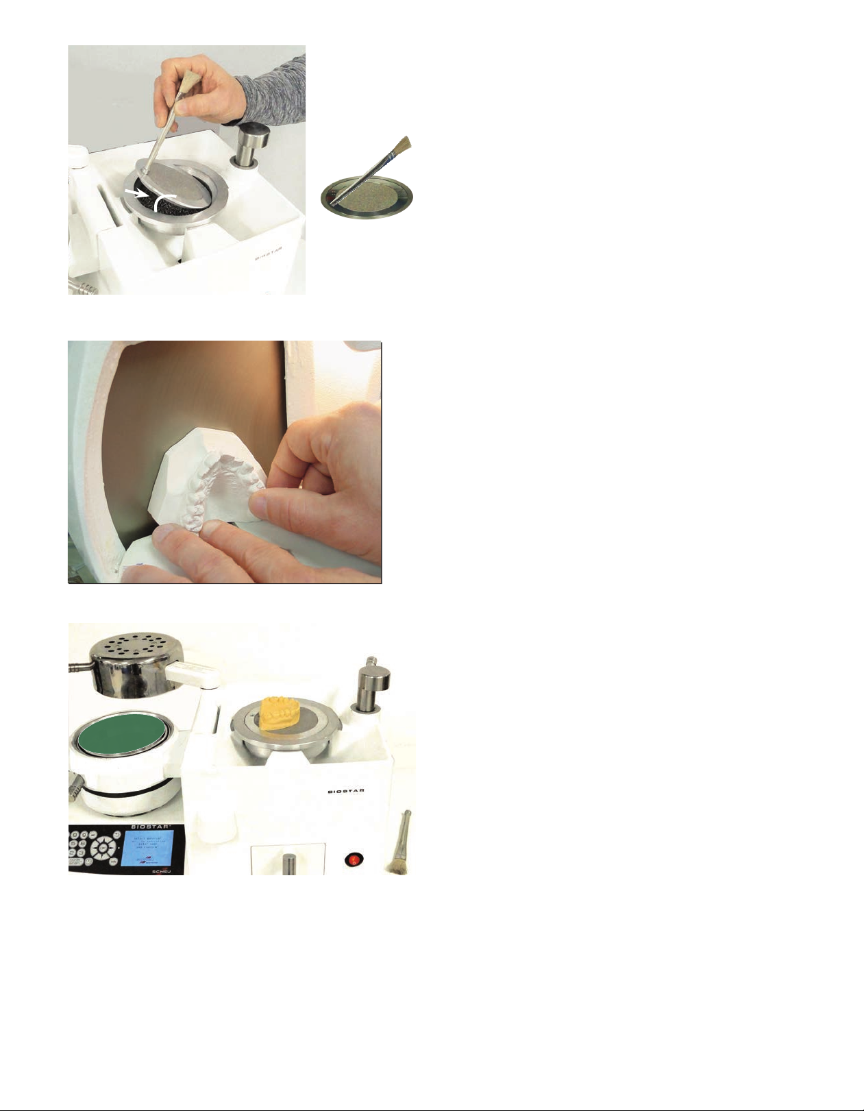
Remove model bubbles and detail the oral anatomy
with a laboratory knife. Fill holes in the model with a
quick-setting stone.
When referencing the model to the platform, make
sure the base of the model is reduced at, parallel
to the occlusal surface. In some cases, the base is
removed creating a at horseshoe model to eliminate
excessive material thinning.
No undercuts under the model base should be
present. This will prevent material from forming
beneath the model base causing potential air leaks
and poor material forming. For some materials, a
liquid separating foil is applied to allow for easy
removal of the formed material.
Position the model on the platform, referencing the
heel toward the material in the pressure chamber,
and incisor segment near the center area of the
platform. Placing the model to the left side of the
platform provides better material forming along
the incisor region.
Apply a liquid model-separating medium, such
as Great Lakes Separator (175-034) or Bioplast
Insulator (175-068) to the dental casts before the
material is formed.
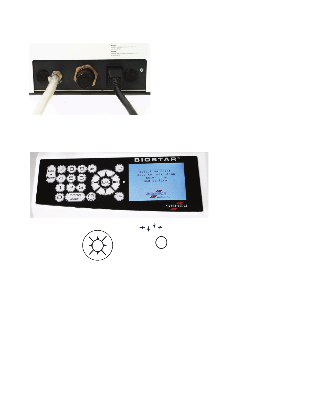
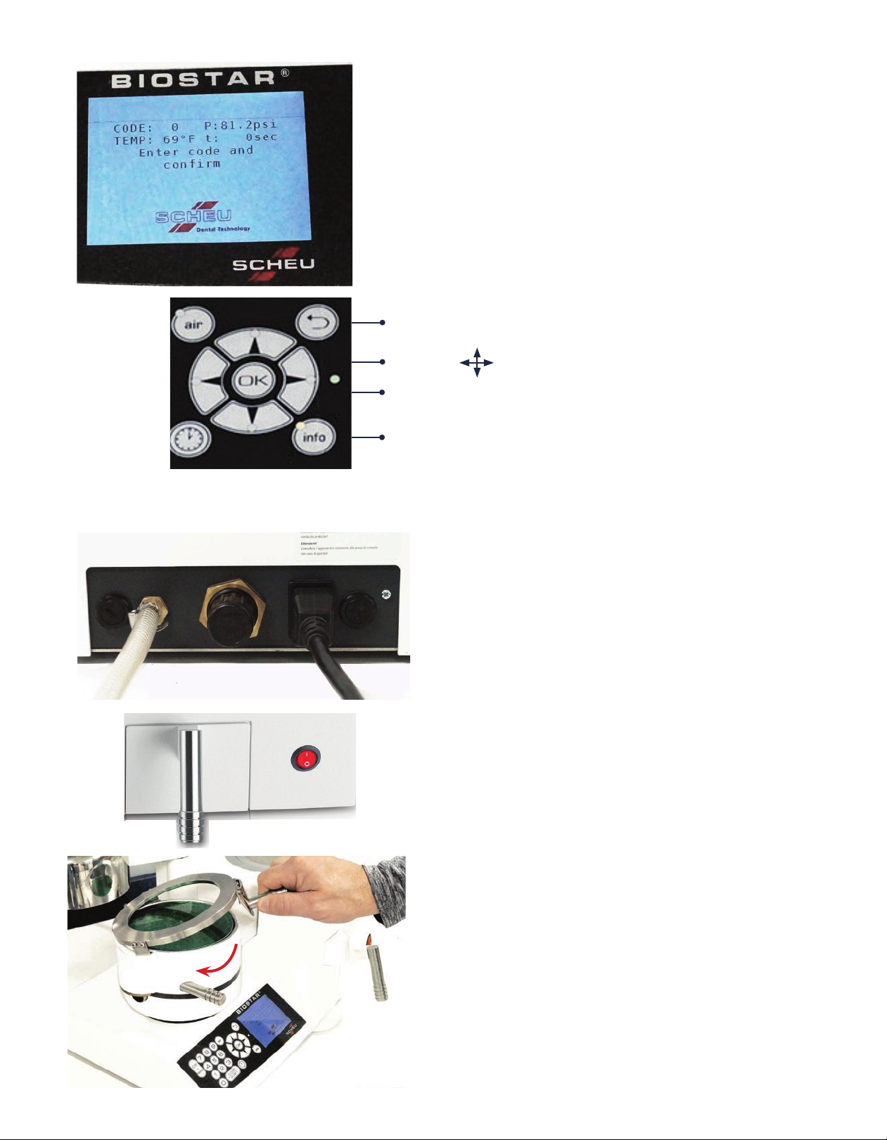
Empty cup or reduce the pellet line to the half-way
level (white arrow). Make sure the inner lip of the
cup is clean. Place the outer ring of the platform
on the inner lip of the pellet cup with the at
platform surface on top (curved white line).
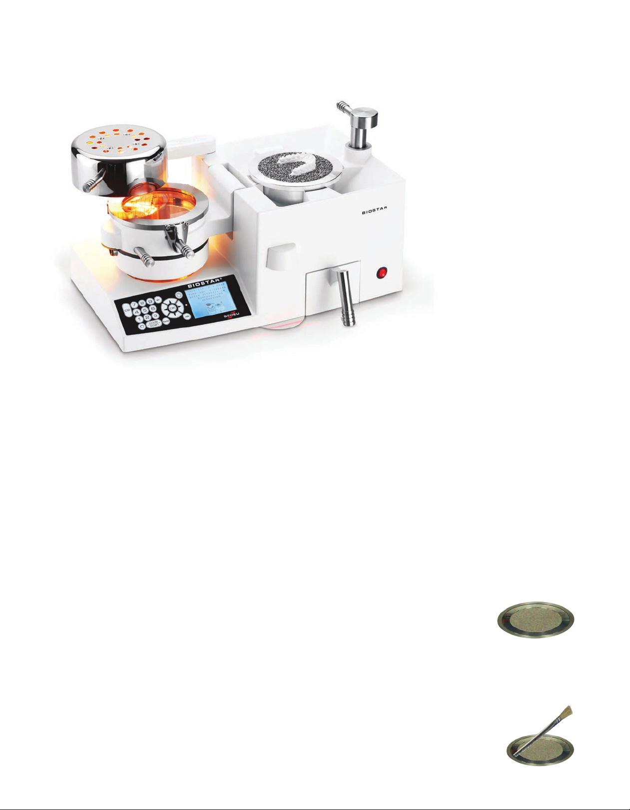
To remove the platform, use the Biostar Brush with
Magnet (016-021).
Engage the tip and lift up.
Pellet Use
A 2.5 pound container of zinc pellets (010-125) is supplied with each Biostar. Pellets are used to
prevent the thermal-plastic materials from stretching over areas of the model that are not part of the
appliance design. Stainless steel pellets (010-099) are also available. The pellets will prevent sealing
the chamber to the cup, and inhibit the pressure-molding process if left on the pellet cup rim.
Note: The use of pellets other than what the manufacturer recommends may result in
machine malfunction and could void the warranty.
Work models are placed in cylindrical pellets to:
•Support the base of the model so that the occlusal-incisal plane is parallel to the rim of the cup
•Prevent the material from forming to the facial surfaces of the teeth, making it hard to remove the
appliance from the work model, and overstretch of the thermal plastic
•Prevent heated material from melting wax used to support the appliance wires on facial areas
Place an adequate amount of pellets in the pellet
cup to elevate the model at the proper level.
Material termination areas, located on the facial
surface of the model, should be referenced at the
same height as the top ledge of the pellet cup.
Note: Mounted models may be referenced
slightly higher than indicated.
Remove the pellet drawer (A) from the machine by
pulling the drawer out using the handle.
To replace the pellet drawer, line up the drawer
with the opening and close the drawer ush to the
machine.
Pour pellets between the model and the inner wall
of the cup (red arrow). Apply additional pellets in
this area as needed.
A

Use a Biostar Brush with Magnet (016-021), to
remove excess pellets, and level the pellet line
from the occlusal-incisal plane to the top rim of
the cup.
Hold the brush at an angle to sweep excess pellets
from the rim of the cup and the palatal area of the
model. Sweep excess pellets around the outside of
the cup to fall in to the pellet drawer (red arrows).
Note: The pellet level should always be to the
top of the cup. The height of the model in the
pellets will change with various applications.
When constructing an orthodontic retainer
(i.e., a Hawley), the pellets placed against the
occlusal-incisal margin cover the wax holding
the wires facially, and act as an insulator when
the heated material is formed.
Improper packing of a model can cause a blowout,
air leak, or machine malfunction. It is important that
there is no sudden drop of the pellet margin at the
inner cup wall, or that the model is not positioned
too high or too low within the cup. This allows the
material to be overstretched, thinning it to where a
hole is created and air blows through. In some
instances, a large air leak could cause inferior
material adaptation that can result in a loose-tting
appliance.
Models attached to articulator mountings may
be referenced slightly higher than indicated.
Mounted models should be split cast. If the model
cannot be removed from the mounting, the pellet
level will need to be at a slight incline to appliance
termination areas.
Note: Make sure the top rim of the cup remains
pellet free. This will provide proper closure and
lockdown of the pressure chamber.

Heating Cycle
There are two options to program the heating times:
1. Manual Entry:
•Press the Power Switch (A) of the Biostar to
activate the machine.
•Press the Time button (B) to manually set the time.
Using the keypad, input the appropriate heating
time (following manufacturer’s suggested heating
time) for the material to be thermal formed. Then
press the Time button again to enter. A default
cooling time will automatically appear during the
pressure-forming process.
-OR-
•Press the Code/Scan button (C) to manually set
both the heating and cooling times. The codes
indicate the length of time for the heating and
cooling phases (See code chart at the end of this
operation manual). To program, press the
Code/Scan button and input the desired 3-digit
code on the keypad. Then press the Code/Scan
button again to enter.
•You are now ready to heat the material. The
Biostar provides instructions on the LCD display
throughout the process. The programmed cooling
time will automatically appear once the material is
pressure formed.
2. Barcode Scan:
The Barcode Scanner automatically
enters the correct processing information
for your material. Press the Code/Scan
button (A) to activate the scanner.
For Great Lakes Material:
The barcode is located on an easy-to-scan
barcode strip (B) inside each box of
material. Hold the barcode strip under the
scanner tilted upward, against the bottom
plate until you hear a ‘beep’ indicating the
barcode has been read. The heating time
will automatically show on the LCD display
(C).
For Scheu Material:
The barcode is printed directly on the
material (D). Hold the material under the
scanner tilted upward, against the bottom
plate until you hear a ‘beep’ indicating
the barcode has been read. The heating
time will automatically show on the LCD
display (C).
Note:
• During long heating cycles or continual
use, the lamp can become extremely hot.
•Caution is advised to prevent skin burns.
A
C
B
A
B
D
C

Position a 125mm diameter round disc on the
spring-loaded adjusting ring of the pressure
chamber.
Tighten by turning the handle clockwise, so that
the chamber and clamping handles are parallel
(curved red arrow).
Align the clamping frame over the material so
that the three clips slip under the bevel of the
locking device on the sides of the chamber.

Swing the heating element from its rest position
over the material (curved red arrow) on the
pressure chamber. When the heater is placed
over the material, the heating element illuminates
and the set heating time begins.
With 5seconds remaining in the heating phase,
warning beeps will sound. Once the heating time
has elapsed, the beeping will be continuous until
the heater is removed from the material.
Material heating times will vary based on compound, color, and thickness. Recommended heating
times are identied on an easy-to-scan barcode strip inside each box of Great Lakes material, and
printed directly on Scheu material. If the proper adaptation is not obtained, it may be necessary to
extend or decrease the recommended heating times by 5-15 seconds.
Note: To ensure a tight seal between the pressure chamber and the cup, pellets should be
completely removed from around the rim.
Pressure Molding Process
After the recommended time is reached, swing
the heating element (A) back to the rest position
(left curved red arrow)and gently ip the pressure
chamber (B) onto the cup (center curved red
arrow). Turn the locking handle (C) from the straight
back rest position 180º toward the front of the
machine (right curved red arrow) until it locks.
This secures the chamber over the cup and allows
air pressure to enter the chamber. The pressure
chamber will not lock in place if pellets, interference,
or improper cup/platform alignment is not obtained.
Once the air pressure is turned on, the digital clock
on the LCD display panel (D) will automatically
initiate a cool-down time. At this point, the material
has been formed over the model and is cooling
under pressure.
At the end of the cooling time, short beeps will
sound. Press the Air button (E) on the control panel
to release the air pressure from the chamber.
Short beeps will sound indicating full pressure
evacuation. If a shorter cooling cycle is required,
the programmed time can be erased and chamber
evacuated by turning o the power switch.
E
A
C
B
D

To unlock the chamber, swing the locking handle
(A) 180º toward the back of the machine
(right curved red arrow) to the straight back
rest position.
Unlock the material held on the chamber by sliding
the clamping frame arm (B) to the left (straight
red arrow). Lift the pressure chamber (C) o the
platform or pellet cup (center curved red arrow)
and remove the model with the formed plastic.
The appliance is now cool to the touch and ready
to be trimmed and nished.
If material was pressure formed in the pellet cup,
some pellets may stick to the formed material
surface. Remove as many pellets as possible with
a lab knife.
Note: Not all pellets can be removed.
Important Troubleshooting Advice
Performing a Cold Test:
A. Turn the Biostar on. Make sure the platform is in place. Clamp a sheet of 2mm (or thicker)
hard material onto the pressure chamber. Secure the clamping frame.
B. Enter 5seconds of heating time. Swing the heating element over the material to activate
the heat. Immediately return the heating element to the rest position.
C. Swing the pressure chamber over the model platform. Activate the air pressure.
D. If you hear a constant rush of air during pressurization (air leak), contact your Great Lakes
Customer Support Specialist immediately.
For fabrication videos, tips, and techniques, visit our website:
GreatLakesDentalTech.com/techniques
A
B
C
Biostar With LCD Display Codes
Chart 2: Cooling Phase
Chart 1: Heating Phase

Important Troubleshooting Advice
Performing a Cold Test:
A. Turn the Biostar on. Make sure the platform is in place. Clamp a sheet of 2mm (or thicker)
hard material onto the pressure chamber. Secure the clamping frame.
B. Enter 5seconds of heating time. Swing the heating element over the material to activate
the heat. Immediately return the heating element to the rest position.
C. Swing the pressure chamber over the model platform. Activate the air pressure.
D. If you hear a constant rush of air during pressurization (air leak), contact your Great Lakes
Customer Support Specialist immediately.
For fabrication videos, tips, and techniques, visit our website:
GreatLakesDentalTech.com/techniques
Biostar With LCD Display Codes
220°C | 427°F
Standard 10 11 12 13 14 15 16 17 18 19 20 21 22 23 24 25 26 27 28 29
Heating Time
Seconds 20 25 30 35 40 45 50 55 60 65 70 75 80 90 100 110 120 140 150 160
Chart 2: Cooling Phase
Code Time
(seconds)
0 0
1 20
2 60
3 120
4 150
5 180
6 240
7 300
8 360
9 420
Chart 1: Heating Phase
Codes
Example: CODE #244CODE #244 = 220°C | 427°F Temperature
2424 == 100100 seconds Heating Time
44== 150150 seconds Cooling Time
Understanding 3-Digit Codes:
• The rst two digits represent the operating temperature of the heating element,
and the length of heating time required prior to the thermal-forming process.
•The third digit represents the cooling phase and the length of time that the
thermal-formed material should be held under pressure.
•All heating and cooling times are in seconds.

Reference Notes

Reference Notes

200 Cooper Avenue, Tonawanda, New York 14150
800.828.7626 U.S. & Canada | 716.871.1161 Worldwide | 716.871.0550 Fax
greatlakesdentaltech.com | info@greatlakesdentaltech.com
SMPI2Rev010920
S-178
Other manuals for BIOSTAR
2
Table of contents
Other SCHEU Medical Equipment manuals
Popular Medical Equipment manuals by other brands

Otto Bock
Otto Bock 28U90 Series Instructions for use

Arjo
Arjo MAXI SKY 600 Operating and Product Care Instructions

3B Medical
3B Medical RESmart BPAP Quick reference sheet

SALUDA MEDICAL
SALUDA MEDICAL Evoke SCS System user manual

DARAY
DARAY SL700 Series installation manual

InMode
InMode VOTIVA Operator's manual