Schick C2 - Profi User manual

. Gebrauchsanweisung
Antriebsgeräte C2 - Profi
Operating Instructions
Schick-C2 - Profi
Mode d'emploi
Schick-C2 - Profi
Georg Schick Dental GmbH
Lehenkreuz 12
D-88433 Schemmerhofen
Telefon 07356/9500-0
Telefax 07356/9500-95
Internet: http://www.schick-dental.de
E-mail: [email protected]

Wir freuen uns, daß Sie sich für ein
technisch hochwertiges Gerät aus
dem Hause SCHICK entschieden haben
und wünschen Ihnen mit Ihrem neuen
C2-Antriebsgerät viel Erfolg und Freude
beim Arbeiten.
Wir haben diese Gebrauchsanweisung
zusammengestellt, um Sie mit Ihrem
neuen Gerät vertraut zu machen und
Ihnen die notwendigen Hinweise für
Bedienung und Wartung zu geben.
We are pleased that you decided to
buy a highly developed piece of
equipment from SCHICK and would
like to wish you every success when
working with your new C2 motor
unit.
We wrote these operating instructions
to enable you to get accustomed to
your new piece of equipment and to
provide you with the correct operating
and maintenance instructions.
Nous nous réjouissons de votre décision
d'utiliser un appareil de haute technicité
de la maison SCHICK et nous vous
souhaitons, avec votre nouvelle pièce à
main C2, beaucoup de satisfications
dans votre travail.
Nous avons rédigé ce mode d'emploi
pour vous familiariser avec votre nouvel
appareil et pour vous fournir les inform-
ations nécessaires pour l'utilisation et
l'entretien de celui-ci.
Index
1.Summary C2-units
2. List of contents - accessories
3. Range of applications
4. General information
Caution !
5. Setting up / operating the unit
6. Exchanging the rotary instruments
7. Replacing the chuck
8. Maintenance and care
9. Possible faults
10.Technical data
11.Declaration of conformity
2
Contenu:
1.Gamme d' appareils C2
2. Contenu livré
3. Domaine d'application et utilisation
4. Indications générales
Attention !
5. Mise en service
6. Changement de fraises
7. Changement des pinces de serrage
8. Entretien
9. Interruptions
10.Données techniques
11.Déclaration de conformité
Inhalt
1.Übersicht C2-Geräte
2. Lieferumfang - Zubehör - ET
3. Einsatz und Gebrauch
4. Allgemeine Hinweise
Achtung !
5. Inbetriebnahme / Betrieb
6. Werkzeugwechsel
7. Spannzangenwechsel
8. Pflege und Wartung
9. Störungen
10.Technische Daten
11.Konformitätserklärung

1. Übersicht: C2-Antriebsgeräte
C2/SK komplett
C2/SF komplett
C2 Linkslaufhandstück
C2 - Digitalanzeige
C2 mit Tempomat
C2-MA
NH / DNH
Artikel-Nr. 6405/01
Artikel-Nr. 6410/01
C2-Motor mit Intramatic-Kupplung
und Kabel
Artikel-Nr. 6200/03
Artikel-Nr. 6200/08
Artikel-Nr. 6380
Zusatzausrüstungen:
Niethammer 1
Artikel-Nr. 1850
Doppelniethammer 2
Artikel-Nr. 1860
1. Summary C2-units
1. Gamme d'appareils
C2-motor unit type SK complete
Moteur C2 type SK complet
C2-motor unit
type SF complete
Moteur C2
type SF complet
Accessories:
équipement complémentaire:
C2 with cruising
speed control
C2 avec 'Tempomat'
C2-digital indicator
C2-indicateur digital
de vitesse
C2 special handpiece for
left hand user
C2 pièce à main rotation
à gauche
C2-motor with INTRA-
matic coupling
Moteur C2 avec
accouplement intramatic
riveting hammer 1
Burin 1
twin riveting hammer 2
double-burin 2
3030
35
35
40
40
25
25
20
20
1515
10
10
5
5
0
0
C-digital
C-digitalSCHICKSCHICK
x1000/min
x1000/min
3
SCHICK NH
SCHICK DNH
12

4
1
4
3030
35
35
4040
25
25
20
20
1515
10
10
5
5
0
0
3
7
2
C-digital
C-digital SCHICK
SCHICK
x1000/minx1000/min
8
2. Lieferumfang - Zubehör / ET
Artikel-Nr.
Komplett
Steuergerät Knieausführung 1
Motorhandstück mit Kabel 2
Handstückablage
mit 2 Spannzangenschlüsseln 3
Netzkabel 4
Aufhängeleiste 5
Schrauben - 2 Stück - 6
6405/01
6435/01
6200
6385
5361
5614
3170
C2/SK mit Digitalanzeige komplett
C2/SK Steuergerät Knieausführung 1
C2/MH Motorhandstück mit Kabel 2
HA Handstückablage
mit 2 Spannzangenschlüsseln 3
Netzkabel 4
Aufhängeleiste 5
Schrauben - 2 Stück 6
Digitalanzeige 7
6405/11
6435/11
6200
6385
5361
5614
3170
6380
C2/SF komplett
C2/SF Steuergerät Fußausführung 8
C2/MH Motorhandstück mit Kabel 2
HA Handstückablage
mit 2 Spannzangenschlüsseln 3
Netzkabel 4
C2/SF mit Digitalanzeige komplett
C2/SF Steuergerät Fußausführung 8
C2/MH Motorhandstück mit Kabel 2
HA Handstückablage
mit 2 Spannzangenschlüsseln 3
Netzkabel 4
Digitalanzeige 7
6410/01
6440/01
6200
6385
5361
6410/11
6440/11
6200
6385
5361
6380
ET Serienmäßig sind die Motorhandstücke
mit Spannzangen Ø 2,35 mm bestückt.
Auf Wunsch lieferbar:
Spannzange Ø 3,175 mm
Spannzange Ø 3,0 mm
Spannzange Ø 2,35 mm
Spannzangenschlüssel
Gegenschlüssel
Ersatzmotorkabel
4332
4117
4114
5160/1
6223
6250
C2/SK
C2/SK
C2/MH
HA
5
6

2. Contenu livré - / pièces de rechange
C2/SK Moteur C2 type SK complet
C2/SK appareil de commande, actionné
avec le genou 1
C2/MH pièce à main avec moteur 2
HA support pour pièce à main
avec deux clés pour changer la pince 3
câble d'alimentation 4
tringle de suspension 5
vis - 2 pièces - 6
no. d'article
6405/01
6435/01
6200
6385
5361
5614
3170
C2/SF Moteur C2 type SF complet
C2/SF appareil de commande, actionné
avec le pied 8
C2/MH pièce à main avec moteur 2
HA support pour pièce à main
avec deux clés pour changer la pince 3
câble d'alimentation 4
6410/01
6440/01
6200
6385
5361
Chucks:
Standard: Ø2.35 mm
Optional Ø 3.0 mm
Ø 3.175 mm
chuck key
counter staywrench
motor cable cpl.
4114
4117
4332
5160/01
6223
6250
Art.-No.
6405/01
6435/01
6200
6385
5361
5614
3170
2. List of contents - accessories/Spare parts
C2/SK motor unit complete
C2/SK knee controller 1
C2/MH motor-handpiece and cable 2
HA handpiece rest
with two keys for changing the chuck 3
mains cable 4
suspension strip 5
screws - 2 pieces - 6
5
C2/SK motor unit complete with
digital indicator
C2/SK knee controller with attachment
for digital indicator 1
C2/MH motor-handpiece and cable 2
HA handpiece rest
with 2 keys for changing the chuck 3
mains cable 4
suspension strip 5
screws -2 pieces - 6
digital indicator 7
6405/11
6435/11
6200
6385
5361
5614
3170
6380
C2/SK Moteur C2 type SK complet avec
indicateur digital de vitesse
C2/SK appareil de commande 1, modèle au
genou equipé pour l'indicateur digital
de vitesse
C2/MH pìece à main avec moteur 2
HA support pour pìece à main
avec 2 clés pour changer la pince 3
câble d'alimentation 4
tringle de suspension 5
vis - 2 pìeces - 6
indicateur digital de vitesse 7
6405/11
6435/11
6200
6385
5361
5614
3170
6380
.
C2/SF motor unit complete
C2/SF foot controller 8
C2/MH motor-handpiece and cable 2
HA handpiece rest
with 2 keys for changing the chuck 3
mains cable 4
6410/01
6440/01
6200
6385
5361
C2/SF motor unit complete with
digital indicator
C2/SF foot controller with attachment
for digital indicator 8
C2/MH motor-handpiece and cable 2
HA handpiece rest
with 2 keys for changing the chuck 3
mains cable 4
digital indicator
6410/11
6440/11
6200
6385
5361
6380
C2/SF Moteur C2 type SF complet avec
indicateur digital de vitesse
C2/SF appareil de commande, modèle au
pied equipé pour l'indicateur digital
de vitesse 8
C2/MH pìece à main avec moteur 2
HA support pour pìece à main
avec 2 clés pour changer la pince 3
câble d'alimentation 4
indicateur digital de vitesse 7
6410/11
6440/11
6200
6385
5361
6380
ET Pince de serrage:
montage de série: Ø 2,35 mm
livrable aux choix:
pince Ø 3,0 mm
pince Ø 3,175 mm
clé p. pince de serrage
contre-clé
cordon C2
4114
4117
4332
5160/1
6223
6250
ET

6
3. Einsatz und Gebrauch
Die C2-Anlagen sind für den Einsatz im Dental-
Labor zum Bearbeiten von Kronen, Brücken sowie
Kunststoff- und Modellgußprothesen konzipiert.
Das patentierte SCHICK - C2 - Antriebsgerät er-
möglicht Ihnen durch seine besondere Konstruktion
(CPU-gesteuert, kollektorlos, robust) ein
laufruhiges, ermüdungsfreies und somit
wirtschaftliches Arbeiten im Dauerbetrieb.
Durch die Prozessorsteuerung wird das Gerät
stets auf Überlastung überwacht. Eine
zweite, computerunabhängige thermische Sicherung
ist als weiterer Schutz eingebaut.
Umgebungsbedingungen:
- Innenräume 5° - 40°
- bis 2.000 m NN
Überspannungskategorie: II
Verschmutzungsgrad : 2
4. Allgemeine Hinweise
4.1 Prüfen, ob Netzdaten mit den Angaben auf dem
Typenschild übereinstimmen.
4.2 Die C2-Anlagen sind nicht für folgenden Einsatz
bestimmt:
- in explosionsgefährdeter Umgebung
- am Patienten
- Bearbeitung feuchter Werkstoffe
- schwerste Kunststoff- und Modellgußarbeiten
4.3 Bei Benutzung sind die einschlägigen Bestimmungen
der Berufsgenossenschaft zu beachten (stets Schutz-
gläser benutzen).
4.4 Motorhandstück keinesfalls mit Druckluft reinigen.
4.5 Beim Ablegen des Motorhandstücks sollte stets ein
Werkzeug oder der werkseitig mitgelieferte Stift
eingespannt sein.
Achtung:
- beim Einsatz von rotierenden Werkzeugen müssen
die Grenzwertangaben der Werkzeughersteller
beachtet werden.
- Reparaturen oder sonstige Eingriffe dürfen nur von
durch SCHICK autorisiertem Fachpersonal vorge-
nommen werden.
- SCHICK übernimmt keine Gewährleistung, wenn
die C2-Anlage nicht in Übereinstimmung mit der
Gebrauchsanweisung gehandhabt wird.
!

7
3. Range of applications
The C2 unit is designed for use in dental laboratories
when trimming crowns and bridges, respectively
acrylic and chrome cobalt dentures.
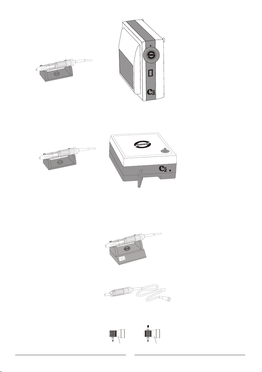
The patented SCHICK - C2 motor unit is constructed
(intelligent, CPU-controlled, robust, no commutator) so
as to run smoothly, thus eliminating user-fatigue and
making it economical to use over long periods of time.
The processor controller constantly monitors the unit
for overloading. A second thermal fuse, which is
independent of the computer, provides further
protection.
Conditions of environment:
- interior 5° - 40 °
- up to 2,000 meter over sea level
Categorie of overvoltage: II
Grade of pollution: 2
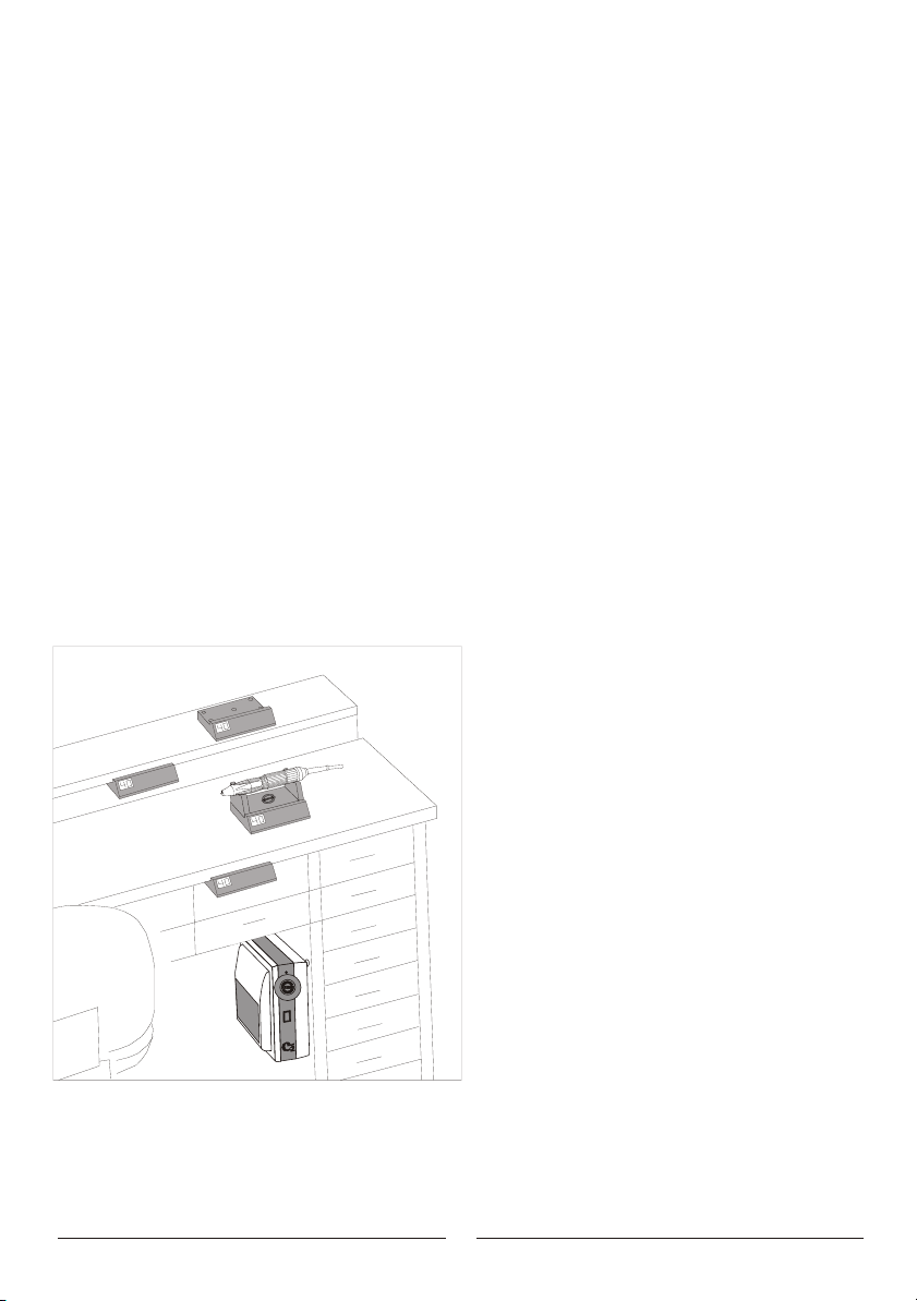
4. General Information
4.1 Ascertain that your mains supply coincides with
the data on the rating plate.
4.2 C2-units are not suitable for the following
applications:
- in areas where there is a risk of explosion
- on patients
- for working on moist materials
4.3 Ensure that all regulatory requirements are
observed during use (always wear protective
glasses).
4.4 Under no circumstances should the motor
handpiece be cleaned with compressed air.
4.5 Before putting the handpiece down, always insert
a rotary instrument or the pin, supplied with the
unit, into the chuck.
Caution:
- When using rotary instruments, do not exceed
the maximum speeds laid down by their
manufacturer.
- Repairs and other technical procedures must only
be carried out by suitable qualified personnel,
authorized by SCHICK.
- Schick do not guarantee the C2 unit should it
not have been used in accordance with the
operating instructions.
3. Domaine d'application et utilisation
Les moteurs C2 sont concus pour l'utilisation au
laboratoire dentaire pour des travaux de faconnage
de couronnes, de bridges, de prothèses en résine
et de prothèses partielles coulées.
L'appareil de commande C2, grâce à sa conception
particulière et brevetée (intelligente, commandée par
processeur robuste et sans collecteur), vous permet de travailler
continuellement, sans fatigue et de façon économique.
Grâce à la commande par processeur, l'appareil
est constamment surveillé pour éviter la surcharge.
Une seconde sécurité thermique indépendante de
l'ordinateur est incorporée comme protection
supplémentaire.
Conditions requises pour le milieu ambiant:
- Dans des pièces intérieurs, entre 5° et 40° C
- Jusq'à 2000 m au-dessus du niveau de la mer
Catégorie de surtension: II
Degré de salissure: 2
4. Indications générales
4.1 Vérifier si les données du réseau concordent avec
celles de la plaquette signalitique.
4.2 Les moteurs C2 ne doivent pas être utilisées:
- en cas de danger d'explosion
- pour travailler en bouche
- pour usiner des matériaux humides
4.3 Respecter les prescriptions professionelles propres
à chaque type d'utilisation (toujours porter des
verres protecteurs).
4.4 Ne jamais nettoyer la pièce à main à l'air comprimé.
4.5 La pièce à main au repos doit toujours être munie
d'une fraise ou de la pointe livrée avec l'appareil.
Attention:
- Respecter les prescriptions du fabricant pour
l'utilisation des fraises
- Toutes réparations ou autres interventions ne
peuvent être faites que par les personnes
qualifiées et autorisées par SCHICK.
- SCHICK ne prend en charge aucune prestation de
garantie dans le cas ou le moteur C2 n'aurait pas
été utilisé selon les prescriptions d'emploi.
!
!

8
5. Inbetriebnahme
Betrieb der Knie- und Fußversion
5.1 Prüfen, ob Netzdaten mit den Angaben auf dem
Typenschild übereinstimmen.
5.2 Netzkabel 12 am Gerät 1einstecken und an-
schließend Netzstecker in die Steckdose stecken.
5.3 Stecker 3 vom Motorkabel in die Steckbuchse 2
an der Rückseite des Gerätes einstecken
(Bajonettverschluß).
5.4 Handstück in die mitgelieferte Ablage 14 legen.
5.5 Netzschalter 4an der Frontseite (bei Fuß-Version
an der Oberseite des Gerätes) drücken (Kontroll-
lampe leuchtet auf). Ausschalten erfolgt durch
nochmaliges Drücken des Netzschalters 4.
nur Knie-Version
5.6 Drehzahlsteller 5 auf die gewünschte Drehzahl
einstellen; durch Drücken der Knieplatte 6
kann die vorher eingestellte Drehzahl stufenlos
erreicht werden.
nur Fuß-Version
5.7 Durch Betätigen des Fußhebels 7kann die
Drehzahl von 1.000 - 40.000 Upm stufenlos
reguliert werden.
19
1
2
18
14
5
6
4
3030
35
35
40
40
25
25
20
20
1515
10
10
5
5
0
0
4
7
C-digital
C-digital SCHICK
SCHICK
x1000/min
x1000/min
3
2
118
12

9
5. Setting up
Operating the knee and foot controller versions
5.1 Ascertain that your mains supply coincides with
the data on the rating plate.
5.2 Plug the mains cable 12 into the unit 1and into
a mains socket.
5.3 Plug the motor cable 3 into the socket 2 on the
rear of the unit (quarter-turn catch).
5.4 Place the handpiece on the rest 14 supplied with it.
5.5 Press the mains switch 4on the front of the unit
(for the foot controller version - on the top). The
control lamp will come on. The unit is switched
off by pressing the mains switch 4again.
Applies to the knee controller version only
5.6 Set the speed controller 5to the desired speed.
The set speed can be reached right away by
pressing the knee controller 6.
Applies to the foot controller version only
5.7 The speed can be varied progressively between
1.000 - 40.000 rpm by moving the pedal 7.
5. Mise en service des versions genou
et à pédale
5.1 Vérifier si les données du réseau concordent avec
celles de la plaquette signalitique.
5.2 Brancher d'abord le câble d'alimentation 12 sur
l'appareil 1et ensuite dans la brise de courant.
5.3 Brancher la fiche mâle 3 du câble du moteur dans
la fiche femelle 2à l'arrière de l'appareil
(emboitement à baionette).
5.4 Poser la pièce à main sur son support 14.
5.5 Appuyer sur le commutateur 4se trouvant sur le
devant de l'appareil, en haut pour la version à
pédale (la lampe de côntrole s'allume).
Version genou uniquement:
5.6 Choisir la vitesse désirée à l'aide du sélecteur de
vitesse 5; la vitesse préselectionnée peut être
atteinte progressivement en appuyant sur le
variateur avec le genou 6 .
Version à pédale uniquement:
5.7 En actionnant la pédale 7, la vitesse peut être
réglée par palliers de 1.000 à 40.000 T/min.

30
30
35
35
40
40
25
25
20
20
15
15
10
10
5
5
0
0
10
Funktionsbeschreibung
Schick-C2 Tempomat
Ist Ihre C2 mit der neuen Tempomat-Steuerung ausge- Möchten Sie eine gespeicherte Drehzahl ändern, be--
rüstet, erlaubt es Ihnen dieses Steuerung nun auch, Dreh- dienen Sie die Knieplatte bis Sie Ihre gewünschte
zahlen, die Sie über einen längeren Zeitraum konstant Drehzahl erreicht haben. Nach ca. 1 sec. wird sodann
halten wollen- z.B. bei Arbeiten unter dem Mikroskop die neue Drehzahl abgespeichert.
oder bei umfangreicheren sonstigen Ausarbeitungen-,
problemlos und einfach abzuspeichern. Die Löschung einer gespeicherten Drehzahl kann
ebenfalls durch Ausschalten der Tempomat-
Ihre C2 mit Tempomat unterscheidet sich bei ausgeschal- steuerung - gelber Leuchtdrucktaster - erfolgen.
teter Tempomatsteuerung - gelber Leuchtdrucktaster auf
Stellung "Aus" - nicht von der Standart - Version.
Bei aktiver Tempomatsteuerung - gelber Leuchtdrucktaster
auf Stellung "Ein" - wird jede beliebige Drehzahl, die Sie
länger als ca. 1 sec. beibehalten, fest abgespeichert.
Danach läuft Ihre C2 mit dieser gespeicherten Drehzahl
ohne weitere Bedienung der Knieplatte so lange weiter,
bis Sie durch kurzes Antippen der Knieplatte diese Dreh-
zahl wieder löschen.
C- digital
C- digital
C-digital
C-digital
C-digital
C-digital
SCHICK
SCHICK
SCHICK
SCHICK
SCHICK
SCHICK
x1000/min
x1000/min
x1000/min
x1000/min
x1000/minx1000/min
Betrieb mit Digitalanzeige
Stecker der Digitalanzeige 19 in die Steckbuchse 18
an der Rückseite des Gerätes einstecken ( nur Knie- und
Fußversion).
Bei eingeschaltetem Gerät zeigt die digitale Drehzahl-
anzeige die durch den Drehzahlknopf vorgewählte
maximale Höchstdrehzahl an.
Bei laufendem Motor wird die tatsächliche Motor-
drehzahl angezeigt. Die digitale Drehzahlanzeige kann
platzsparend unter die Handstückablage gestellt
werden oder ist je nach Wunsch auch am Arbeitstisch
zu befestigen - mittels doppelseitigem Klebeband - .
C-digital
C-digitalSCHICK
SCHICK
x1000/min
x1000/min

11
Function of Cruising
Speed Control - Tempomat
If your new C2 is equipped with a Cruising
Speed Control - Tempomat!
Cruising speed control switched on:
- yellow lamp is shining
- each speed which is kept more than 1 sec. is stored
- without pressing the knee-/foot controller the motor is
running with the speed stored
- by operating the knee-/foot-control again the stored
speed is canceled
- to select a new speed please operate the knee-/foot-
control again until the desired speed is reached and keep
the control for 1 sec. at this speed; the new speed then
is stored.
A stored speed can be canceled by switching off the
cruising speed control (yellow lamp "off"). Then there is
no operational difference to the standard model.
Operating the unit with a digital display
Insert the plug on the digital display 19 into the socket 18
in the rear of the unit.
When the unit is switched on, the digital speed indicator
shows the pre-selected maximum speed. Once the motor
is running, the actual speed of the motor is displayed.
To save space, the digital speed indicator can be placed
under the handpiecerest or, if required, adhered to a
bench top with double-sided adhesive tape.
Fonctionnement avec indicateur
numérique
Enfoncer la prise de l'indicateur numérique 19 dans la
fiche femelle 18, située sur la face arrière de l'appareil.
Quand l'appareil est sous tension, l'affichage digital de
la vitesse de rotation indiquera la vitesse maximale de
rotation préselctionnée. Lorsque le moteur tourne, sa
vitesse de rotation réelle sera indiquee.
L'indicateur numérique de la vitesse de rotation pourra
être posé, pour un gain de place, sous le support de
pièce á main, ou selon votre choix, fixé à la table de
travail à l'aide d'un adhesive double face.
Descriptif
SCHICK-C2 avec Tempomat
Quand votre C2 est équipé du nouveau système Tempomat,
cet équipement vous permet de bloquer la vitesse dont
vous avez besoin d'une manière constante pour un travail
particulier ( sous binoculaire ou autre..).
Ce blocage est facile à annuler.
Le Tempomat de votre C2 est commandé par le bouton-
poussoir correspondant. Pour activer le Tempomat,
presser sur le bouton-poussoir - le voyant jaune s'allume
- et dès lors, chaque vitesse utilisée plus de 1 seconde sera
bloquée. Votre moteur C2 fontionne sans le contact du
genou avec le boitier de commande ou de la pédale du
modèle au pied.
On annulera 'ordre par une nouvelle pression sur le
plateau ou sur la pédale.
Vous souhaitez seulement modifier la vitesse en continu:
avec le plateau de la commande au genou, sélectionner
la nouvelle vitesse et maintir au moins 1 seconde; idem
avec la pédale du variateur au pied.
L'annulation du blocage s'obtient également par
l'extinction du voyant jaune..

12
6. Werkzeugwechsel
Durch Drehen des Griffmantels 13 am Handstück
kann die Spannzange ge- bzw. entspannt werden.
Achtung:
Werkzeugwechsel nur bei ausgeschaltetem Motor!
Im Hinblick auf Genauigkeit und Lebensdauer der
Spannzange muß - auch bei Nichtbetrieb - immer ein
Werkzeug oder der werkseitig mitgelieferte Schutzstift
eingespannt sein.
Bei Werkzeugen mit kurzen Schäften ist darauf zu
achten, daß das Werkzeug nur so tief eingespannt
wird, daß es nicht an der Handstückspitze aufsitzt.
13
auf
zu
6. Exchanging the rotary instruments
The chuck is opened, respectively, closed by turning
the outer sleeve 13 on the handpiece.
Caution:
Only ever exchange the rotary instrument with the
motor switched off!
With regard to the precision and service-life of the
chuck, an instrument must always be inserted into it
- even when the handpiece is not in use.
Should the instrument have a short shank, ensure that
the head of the instrument does not rub on the end of
the handpiece.
6. Changement des fraises
La pince de serrage est ouverte ou fermée en tournant
l'extrêmité 13 de la pièce à main.
Attention:
Ne changer l'instrument que lorsque le moteur est à
l'arrêt. Pour conserver la précision et préserver la
durée de vie de la pince de serrage, elle doit toujours
être munie d'un instrument, même au repos. Pour
les fraises à tiges courtes, faire attention à ce que
l'instrument ne frotte pas sur l'extrêmité de la pièce
á main.

13
Achtung:
Spannzangenschlüssel 22 und Gegenschlüssel 23
finden Sie in der Unterseite der Handstückablage!
Soll anstelle der serienmäßig eingebauten 2,35 mm
Spannzange eine 3,00 mm Spannzange eingebaut
werden, muß die in der Handstückspitze montierte
Einsatzbuchse durch eine andere (Artikel-Nr. 6279)
ersetzt werden. Hierzu die Einsatzbuchse 17 aus
der abgenommenen Handstückspitze nach unten
ausdrücken und die neue Buchse entsprechend
einsetzen.
Bei einem Linkslaufhandstück (Kennzeichnung blauer
Ring) erfolgt der Spannzangenwechsel sinngemäß,
jedoch mit Linksgewinde.
zu
auf
20
17
21
22
22
15
16
12
23
7. Spannzangenwechsel
7.1 Spannzange öffnen und Werkzeug entnehmen.
Spitze 21 (Rechtsgewinde) abschrauben. Bei fest-
sitzenden Spitzen kann die ausgefräste Seite des
Spannzangenschlüssels Nr. 5160/1 22 zu Hilfe
genommen werden, indem der Steg des Schlüssels
in die dafür vorgesehende Nut der Spitze eingreift.
7.2 Motorkabel 20 entfernen. Hierzu Kappe 15 vom
Motor abschrauben und Kabel durch Abziehen des
Steckkörpers 16 lösen. Bitte beachten, daß die
Werkzeugspannung geöffnet ist. Gegenschlüssel
Nr. 6223 23 motorseitig auf Welle aufstecken.
Mit Spannzangenschlüssel Nr. 5160/1 22 über
dem Dreikant der Spannzange eingreifen. Um
Verformungen der Spannzange zu vermeiden, muß
bei geöffneter Werkzeugspannung immer ein Werk-
zeugschaft oder der mitgelieferte Stift in der Spann-
zange stecken. Gegenschlüssel Nr. 6223 23
festhalten und durch Drehen des Spannzangen-
schlüssels entgegen dem Uhrzeigersinn die
Spannzange lösen und herausdrehen - Spannzange
hat Rechtsgewinde!
7.3 Spannzange reinigen, außen leicht einfetten und in
die Welle einsetzten. Mit Schlüsseln wie unter Punkt
7.2 beschrieben die Spannzange im Uhrzeigersinn
bis Endanschlag einschrauben und leicht festziehen.
Steckkörper 16 aufstecken und mit Kappe 15
wieder verschrauben. Handstückspitze 21 auf-
. schrauben.
.

14
7. Replacing the chuck
7.1 Open the chuck and withdraw the rotary instrument.
Unscrew the end of the handpiece 21 (right-handed
thread). Should the end be too tight to unscrew,
use the milled side of a No. 5160/1 22 chuck tool
by placing its bar in the slot in the end of the hand-
piece.
7.2 Remove the motor cable 20. To do so, unscrew the
cap 15 from the motor and loosen the cable by
pulling it out of the plug-in seal 16. Please ensure
that the chuck is open. Use a No. 6223 wrench 23
to hold the motor end of the spindle.
Engage the triangular section of the chuck with a
No. 5160/1 chuck tool 22. To prevent the chuck
becoming distorted, an instrument shank or the
pin supplied must always be inserted into it. Hold
the No. 6223 wrench tightly and turn the chuck
tool anti-clockwise to unscrew the chuck
completely - the chuck has a right-handed thread!
7.3 Clean the chuck, grease it lightly and place it in the
spindle. Use the tools to screw the chuck in - clock-
wise and as far as possible - as described in section
7.2, and tighten it slightly.
Replace the plug-in seal 16 and screw the cap 15
back into place. Screw the end of the handpiece 21
on again.
Please note:
The tools 22 and 23 are to be found in the base
of the handpiece rest!
If you intend to replace the standard 2.35 mm chuck
with a 3.0 mm version, the bush in the end of the
handpiece must be replaced with a new one (article
No. 6279). To do so, remove the end of the hand-
piece, press the bush 17 downwards, out of the tip
and place the new bush in position.
When using a special handpiece for left hand (marked
with blue ring) the chuck is replaced accordingly, but
with left handed thread.
7. Changement de la pince de serrage
7.1 Ouvrir la pince et sortir la fraise. Dévisser le nez 21
se trouvant à l'extrêmité (pas da vis à droite).
Si ce dernier est bloqué, utiliser la partie creusée
de la molette No. 5160/1 22 que l'on placera dans les
2 creneaux du nez afin d'aider le dévissage.
7.2 Enlever le câble moteur 20. Pour cela, dévisser le
capuchon 15 du moteur et détacher le câble en
tirant sur le raccord 16. Veiller que la pince de
serrage de l'outil soit bien ouverte.
Introduire la contre-clé No. 6223 23 dans l'axe côté
moteur. Placer la clé pour la pince de serrage No. 5160/1
22 dans la pince de serrage à trois pans.Pour éviter la
déformation de la pince de serrage, il faut veiller,
à y laisser engager un outil ou la pointe livrée. Pour
extraire la pince de serrage, il faut maintenir la
contre-clé No. 6223 23 et tourner la clé pour pince
de serrage dans le sens inverse des aiguilles d'une
montre - la pince de serrage a un pas de vis a droite!
7.3 Nettoyer la pince de serrage, la graisser légèrement
et la replacer dans l'axe. A l'aide des clés, comme
décrit au paragraphe 7.2., revisser la pince de
serrage dans le sens des aiguilles d'une montre
jusqu'à la butée et serrer légèrement.
Fixer le raccord 16 et revisser le capuchon 15.
Revisser le nez de la pièce à main! 21
Attention:
Vous trouverez la clé pour pince de serrage 22 et la
contre-clé 23 sous le support de pièce à main!
Lorsqu'une pince de serrage de 2.35 mm, montée
en serie, doit être remplacée par une pince de 3.0 mm,
il faudra remplacer, dans le nez de la pièce à main,
la douille de guidage par une autre (article No. 6279).
Pour cela, éjecter vers le bas la douille de guidage 17
du nez de la pièce à main démonté et replacer conformément
à la nouvelle douille.
Pour une pièce à main rotation à gauche reconnaissable
par sa baque bleue, le sens de démontage de la pince de
serrage est inversé: dévisser à droite.
17
21
zu
auf
20
22
15
16
22
12
23

15
9. Störungen
Wird das Handstück überbelastet bzw. blockiert,
schaltet das Gerät aus Sicherheitsgründen ab.
- beim Fuß- und Kniesteuergerät Fußhebel bzw.
Knieplatte in die 0-Position bringen und wieder
neu betätigen; das Gerät ist dann sofort wieder
einsatzbereit.
-
8. Pflege und Wartung
Achtung: C2-Motorhandstücke nicht mit
Druckluft reinigen!
Spannzange von Zeit zu Zeit, je nach Verschmutz-
ungsgrad, reinigen und neu fetten, sowie Spitzen-
bereich ausbürsten - siehe Punkt 7 -.
Da die C2-Anlagen weder Kollektoren, noch Kohlen
und Lüftungsöffnungen haben, ist keine weitere
Wartung erforderlich.
8. Care and maintenance
Caution: Do not clean your C2 motorhandpiece
with compressed air !
The chuck should be cleaned and re-greased once
in a while, depending on how dirty it is (refer to
section 7).
As C2 units have no commutators, carbon brushes
or ventilation parts, no further maintenance is
required.
9. Possible faults
Should the handpiece be overloaded, respectively,
jammed, for safety reasons the unit will switch
itself off.
- When using a foot or knee controller, release the
pedal switch, respectively knee switch and operate
it again; the unit is ready for use immediately.
8. Entretien
Attention: La pièce à main C2 ne doit pas être
nettoyée à l'air comprimé.
La pince de serrage doit être, de temps en temps
et en fonction du degré d'encrassement, être
nettoyée et graissée (voir chapitre7).
Puisque les moteurs C2 n'ont ni collecteur, ni
charbons et ouvertures d'aération, il n'est pas
nécessaire de procéder à un entretien plus poussé.
9. Interruptions
Si la pièce à main est surchargée ou bloquée, le
moteur s'arrête pour des raisons de sécurité.
- En cas d'emploi d'une commande au pied ou au
genou, lâcher et appuyer de nouveau; l'appareil
est de nouveau immédiatement prêt à fonctionner.

16
Diese Gebrauchsanweisung ist stets erreichbar, am
besten in der Nähe des Gerätes aufzubewahren!
An dieser Stelle möchen wir Sie auch darauf hinweisen,
daß für solche technisch hochwertigen Geräte ein
entsprechender Reparaturservice und speziell ausge-
bildetes Fachpersonal erforderlich ist.
Das Haus SCHICK garantiert Ihnen einwandfreie
Reparaturen mit Original-Ersatzteilen. Auf jede bei uns
im Hause durchgeführte Reparatur wird Ihnen wieder
eine Garantiezeit von 6 Monaten eingeräumt.
10. Technische Daten
C2/SK C2/SF
Abmessungen: Breite 120mm 230mm
Höhe 230mm 110mm
Tiefe 245mm 245mm
Gewicht 3,3Kg 3,3Kg
C2-MH Länge 180mm
Gewicht 240g
Nennspannung: AC 220-240V 115 V 100V
Nennfrequenz: 50/60Hz
Aufnahmeleistung: 170 W
Gerätetyp: C2 - Profi
Handstückmodell: 6xx.xxx
Drehzahlbereich: 1.000 - 40.000 Upm
Schutzklasse: II
Das Gerät entspricht den geltenden Bestimmungen
nach VDE bezüglich der Gerätesicherheit und des Funk-
schutzes.
Die C2-Anlage ist ein Gerät der Gruppe III nach
Med. GV Typ B ohne Anwendungsteil.
Hersteller:
VV
DEE
Georg Schick Dental GmbH
Lehenkreuz 12
D-88433 Schemmerhofen
Telefon 07356/9500-0
Telefax 07356/9500-95
Internet: http://www.schick-dental.de
E-mail: [email protected]

Fabricant:
VV
DEE
17
manufacturer:
VV
DEE
10. Technical Data
Dimensions:
Weight:
C2-MH Length: 180mm Weight 240g
Power supply:
Nominal frequency:
Power input:
Type:
Handpiece model:
Speed range:
Safety class
This unit complies with the current VDE (German
association of electrical technicians) regulations
concerning safety and suppression.
The C2 is a group III unit according to Med. GV type B,
and does not include an application component.
These operating instructions should be readily access-
ible and are best kept close to the unit itself.
We would like to take this opportunity to advise you
that a proper repair service and suitable qualified
personnel are required for such highly developed
technical equipment.
SCHICK guarantees to carry out perfect repairs using
original spare parts.
Width:
Height:
Depth:
120mm 230mm
230mm 110mm
245mm 245mm
3,3 Kg 3,3Kg
AC 220-240V 115V 100V
50/60Hz
170W
C2
6xx.xxx
1.000 - 40.000 rpm
II
C2/SK C2/SF
10. Données techniques
Dimensions:
Poids::
C2-MH longueur 180mm poids 240g
Tensions nominale:
Fréquence nominale:
Puissance:
Type d'appareil:
Pièce à main
model No
Intervalle de
puissance:
Class de protection:
L'appareil est conforme aux éxigences de la VDE (asso-
ciation électronique allemande) en ce qui concerne la
sécurité des appareils et la protection radiotélegraphique.
Le dispositif C2 est un appareil du groupe III d'après
Med. GV Type B sans pièce d'application.
Ce mode d'emploi est conservé à portée de main,
de préférence à proximité de l'appareil!
A ce propos, nous vous informons, que pour de tels
appareils de haute technicité, un service de réparation
compétent et un personnel hautement qualifié
sont necessaires.
La maison SCHICK vous garantit des réparations
parfaites avec des pièces de rechange d'origine.
largeur
hauteur
profondeur
120mm 230mm
230mm 110mm
245mm 245mm
3,3 Kg 3,3Kg
AC 220-240V 115V 100V
50/60Hz
170W
C2
6xx.xxx
1.000 - 40.000 rpm
II
C2/SK C2/SF
Georg Schick Dental GmbH
Lehenkreuz 12
D-88433 Schemmerhofen
Telefon 07356/9500-0
Telefax 07356/9500-95
Internet: http://www.schick-dental.de
E-mail: [email protected]
Georg Schick Dental GmbH
Lehenkreuz 12
D-88433 Schemmerhofen
Telefon 07356/9500-0
Telefax 07356/9500-95
Internet: http://www.schick-dental.de
E-mail: [email protected]

Declaration of Conformity
We, GEORG SCHICK DENTAL GmbH
Lehenkreuz 12
88433 Schemmerhofen
declare herewith, that the product
C2 - Installations consisting of
C2 Motorhandpiece 6200 connected with
C2 Control unit 6435 or 6440
is in conformity with the following provisions of Directiive:
92/59/EWG (allgemeine Produksicherheit)
89/392/EWG (Maschinenrichtlinie)
73/23/EWG (Niederspannungsrichtlinie)
89/336/EWG (EMV-Richtlinie)
According to following standards:
EN 61010/1 (Elektrische Ausrüstung von
Maschinen)
EN 55014 (Funkentsörung)
EN 55104 Teil 1 (Störaussendung)
EN 292 (Sicherheit von Maschinen)
DIN/IEC 601/1 (Sicherheit von Maschinen)
Schemmerhofen, August 1997
Déclaration de conformité
Nous, GEORG SCHICK DENTAL GmbH
Lehenkreuz 12
88433 Schemmerhofen
déclarons que le produit
Installation C2 comprenant
Pièce à main C2 6200
Appareils de commande 6435 ou 6440
est conform aux dispositions des directives:
92/59/EWG (allgemeine Produksicherheit)
89/392/EWG (Maschinenrichtlinie)
73/23/EWG (Niederspannungsrichtlinie)
89/336/EWG (EMV-Richtlinie)
et aux normes ou autres documents normatifs appliqués:
EN 61010/1 (Elektrische Ausrüstung von
Maschinen)
EN 55014 (Funkentsörung)
EN 55104 Teil 1 (Störaussendung)
EN 292 (Sicherheit von Maschinen)
DIN/IEC 601/1 (Sicherheit von Maschinen)
Schemmerhofen, Août 1997
Konformitätserklärung
Wir, GEORG SCHICK DENTAL GMBH
Lehenkreuz 12
D-88433 Schemmerhofen
erklären hiermit, daß das Produkt
C2-Anlage bestehend aus
C2-Motorhandstück 6200 in Verbindung mit
C2-Steuergerät 6435 oder 6440
Folgenden einschlägigen Bestimmungen entspricht:
92/59/EWG (allgemeine Produktsicherheit)
89/392/EWG (Maschinenrichtlinie)
73/23/EWG (Niederspannungsrichtlinie)
89/336/EWG (EMV-Richtlinie)
Angewendete harmonisierte Normen:
EN 61010/1 (Elektrische Ausrüstung von
Maschinen)
EN 55014 (Funkentstörung)
EN 55104 Teil 1 (Störaussendung)
EN 292 (Sicherheit von Maschinen)
DIN/IEC 601/1 (Sicherheit von Maschinen)
Schemmerhofen im August 1997
W. Schick
Geschäftsführer
W. Schick
Geschäftsführer
W. Schick
Geschäftsführer
04/2001
Table of contents
Other Schick Dental Equipment manuals

Schick
Schick QUBE II User manual

Schick
Schick MT A User manual

Schick
Schick Q3 User manual

Schick
Schick CDRPan User manual

Schick
Schick QUBE II Operation instructions

Schick
Schick CDRPan User manual

Schick
Schick Q3 User manual

Schick
Schick C1-Master User manual

Schick
Schick G2 Concept User manual

Schick
Schick Qube User manual
Popular Dental Equipment manuals by other brands

GoodDrs
GoodDrs Dr's Finder user manual

Komet
Komet ER Cast Series Instructions for use

Myray
Myray RX DC Technical manual

Durr Dental
Durr Dental VistaScan Mini View 2.0 XPS07.2D Series Installation and operating instructions

BRASSELER USA
BRASSELER USA NL4500 Operation manual

ivory
ivory Neo Line SL411E Operation manual