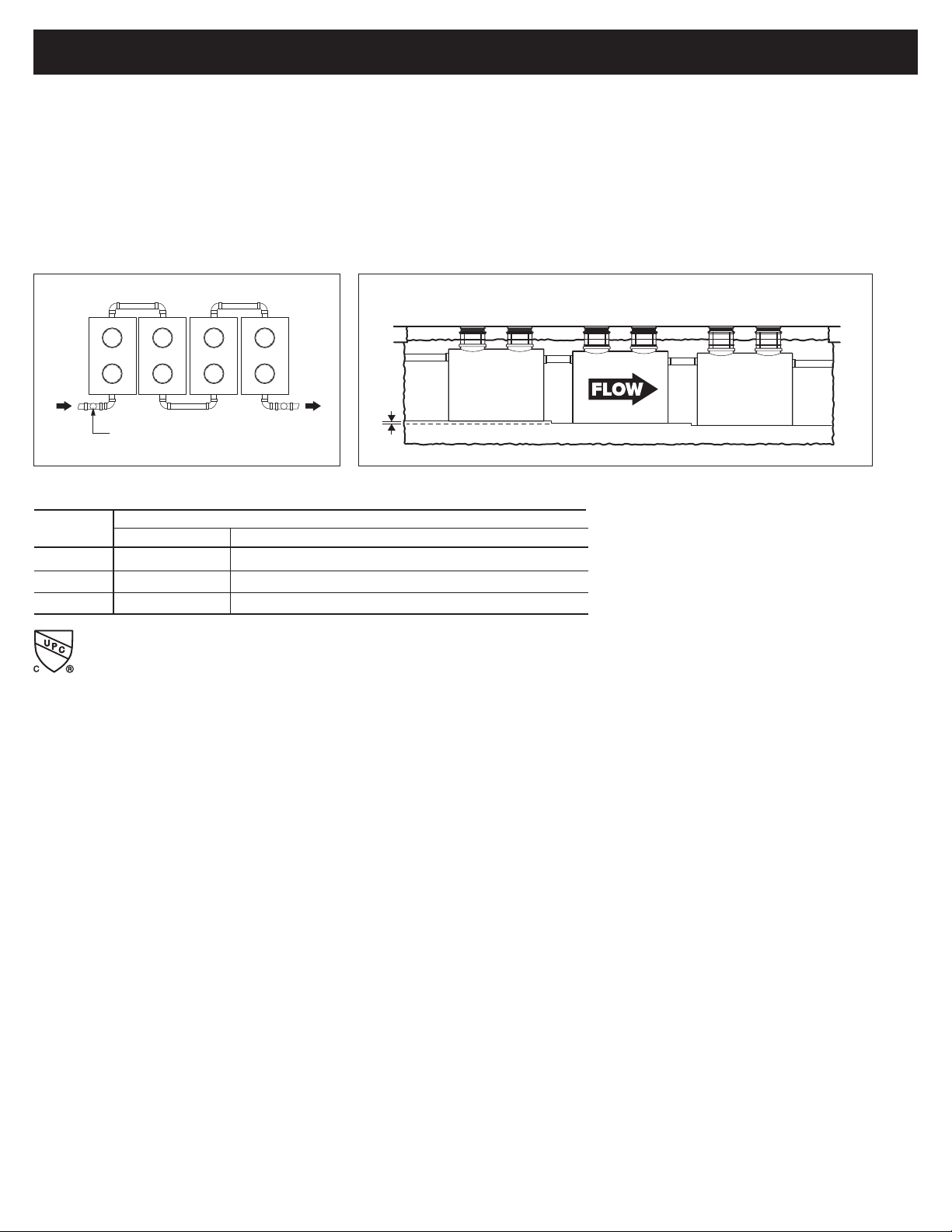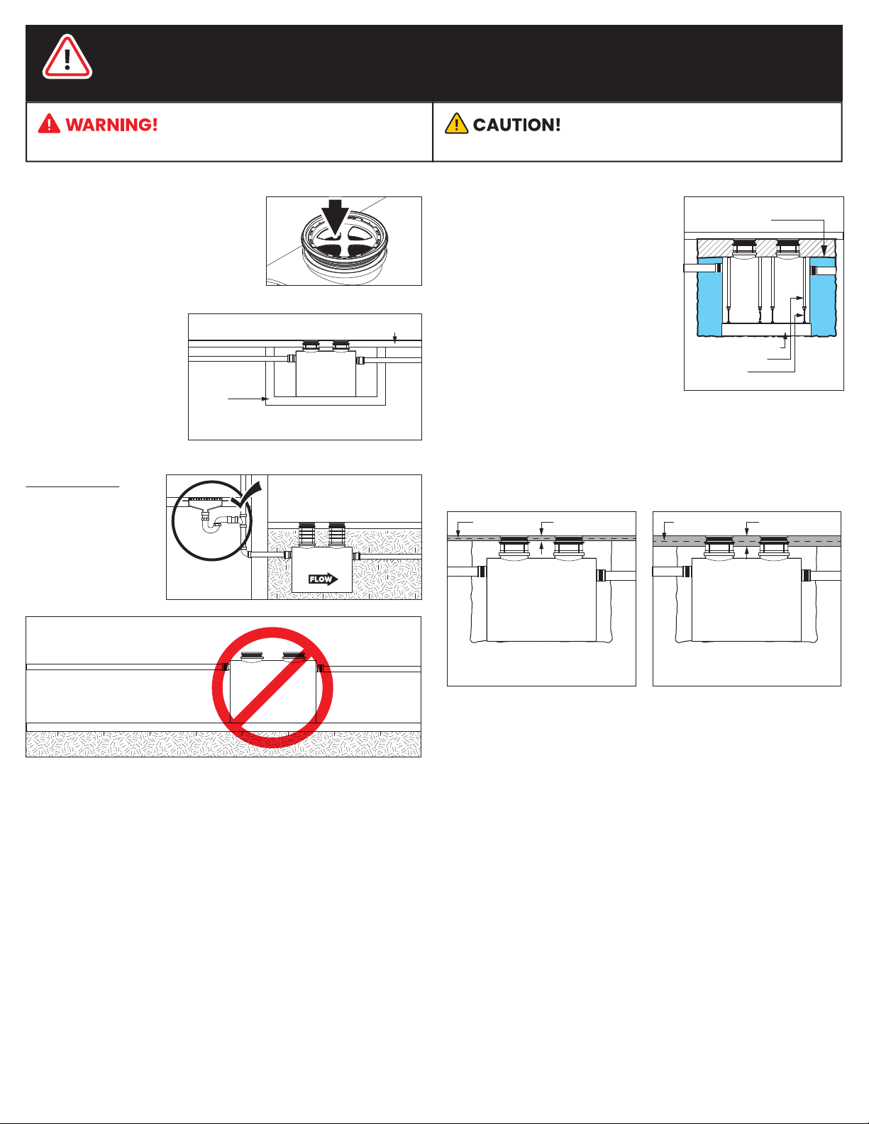
DO NOT INSTALL
ABOVE GRADE
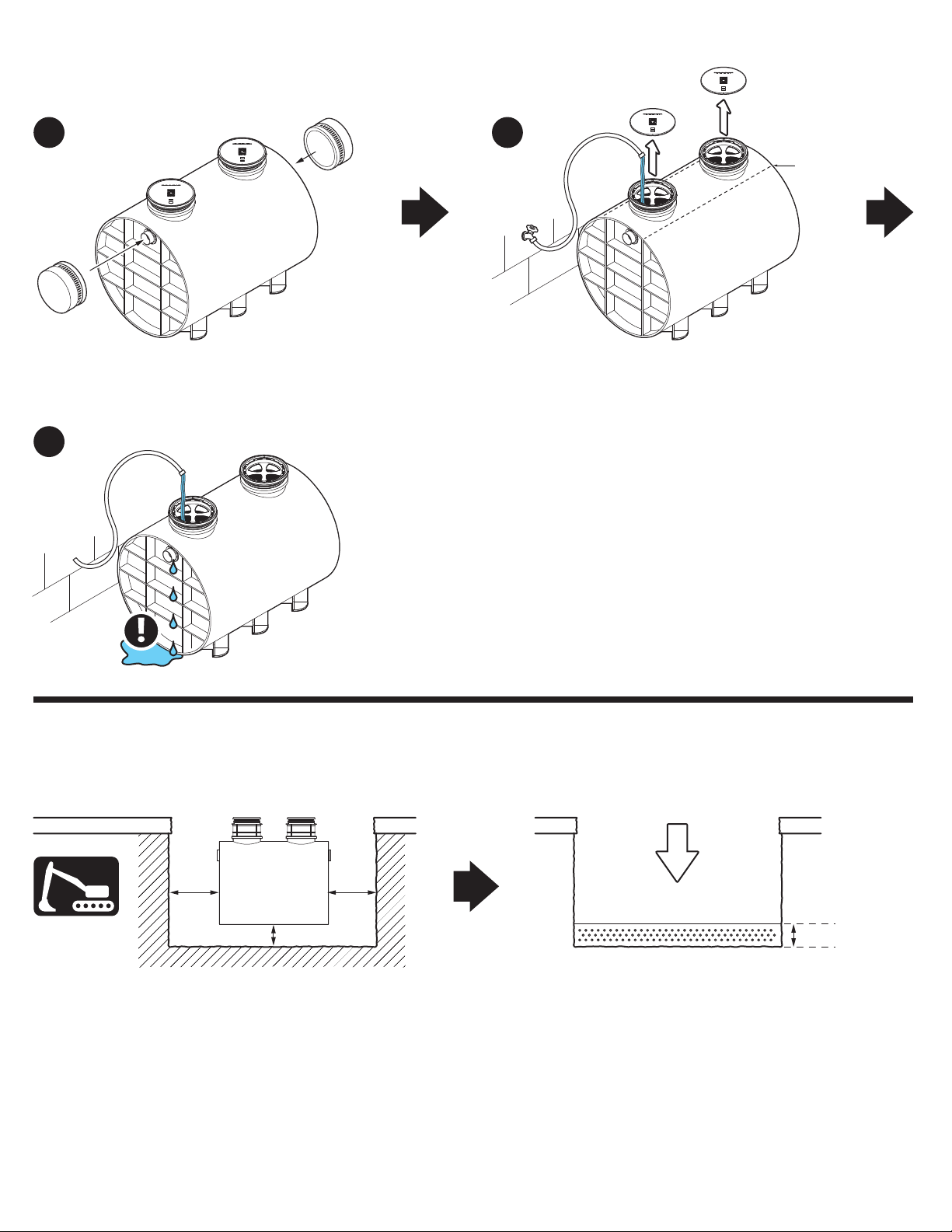
Installation Instructions
Installation instructions and additional
components are included with the
interceptor. Read all instructions prior to
installation. This interceptor is intended
to be installed by a licensed plumber in
conformance with all local codes.
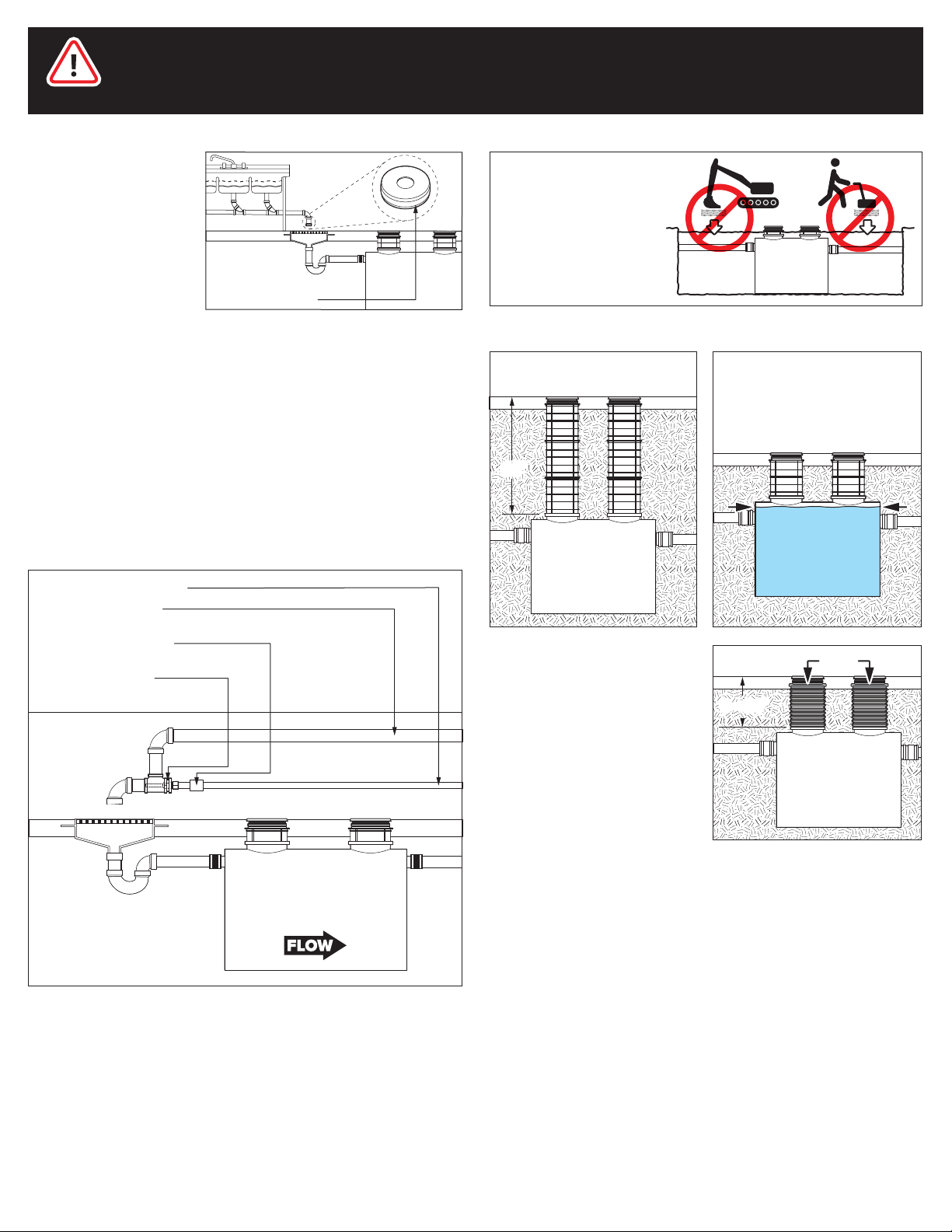
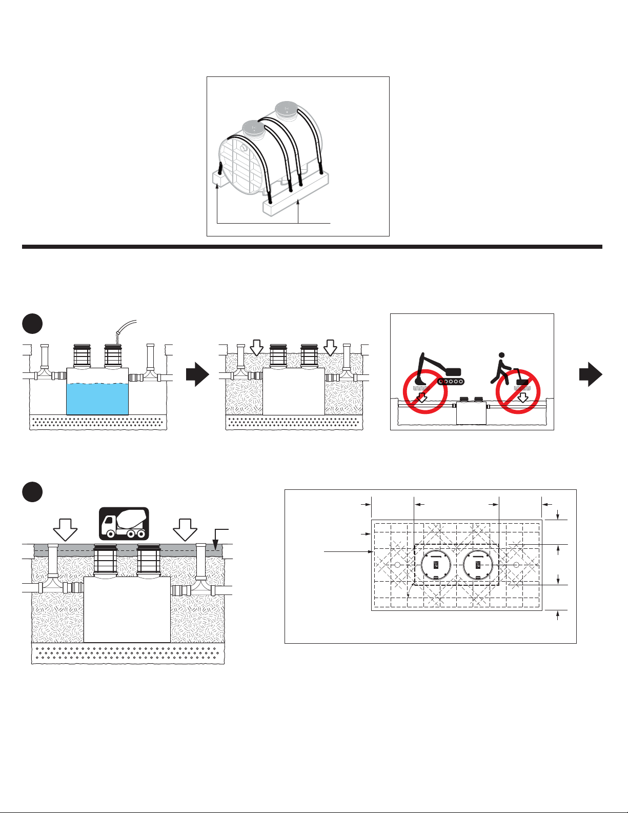
High Water Table Installations
Interceptors and risers are not designed
to withstand water table height in excess
of the top of the unit when buried (see
figure). If it is possible for this to occur,
install the interceptor and risers in a
water-tight concrete vault or backfill with
concrete or flowable fill (wet concrete
and flowable backfill should be poured
in stages to avoid crushing the
interceptor). At risk areas include but are
not limited to tidal surge areas,
floodplains and areas that receive storm
water. Great Basin™models that are direct buried in high water table
scenarios must be installed with an anchor kit. Model GB-1000-B uses
model AK3 anchor kit for use with deadmen anchors.
max water table height
for direct burial
deadman anchor
polyester strap
turnbuckle
Below Grade Installation Slab Requirements
A concrete slab to finished grade with rebar is required when
installing interceptor below grade.
Pedestrian Traffic or
Greenspace Areas Vehicular Traffic Areas
4" min. slab 8" min. slabRebarRebar
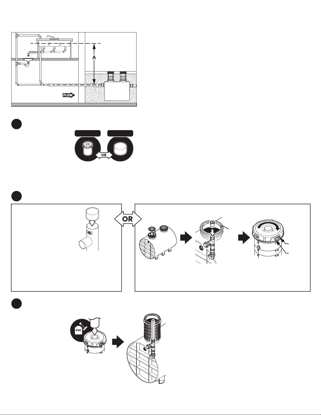
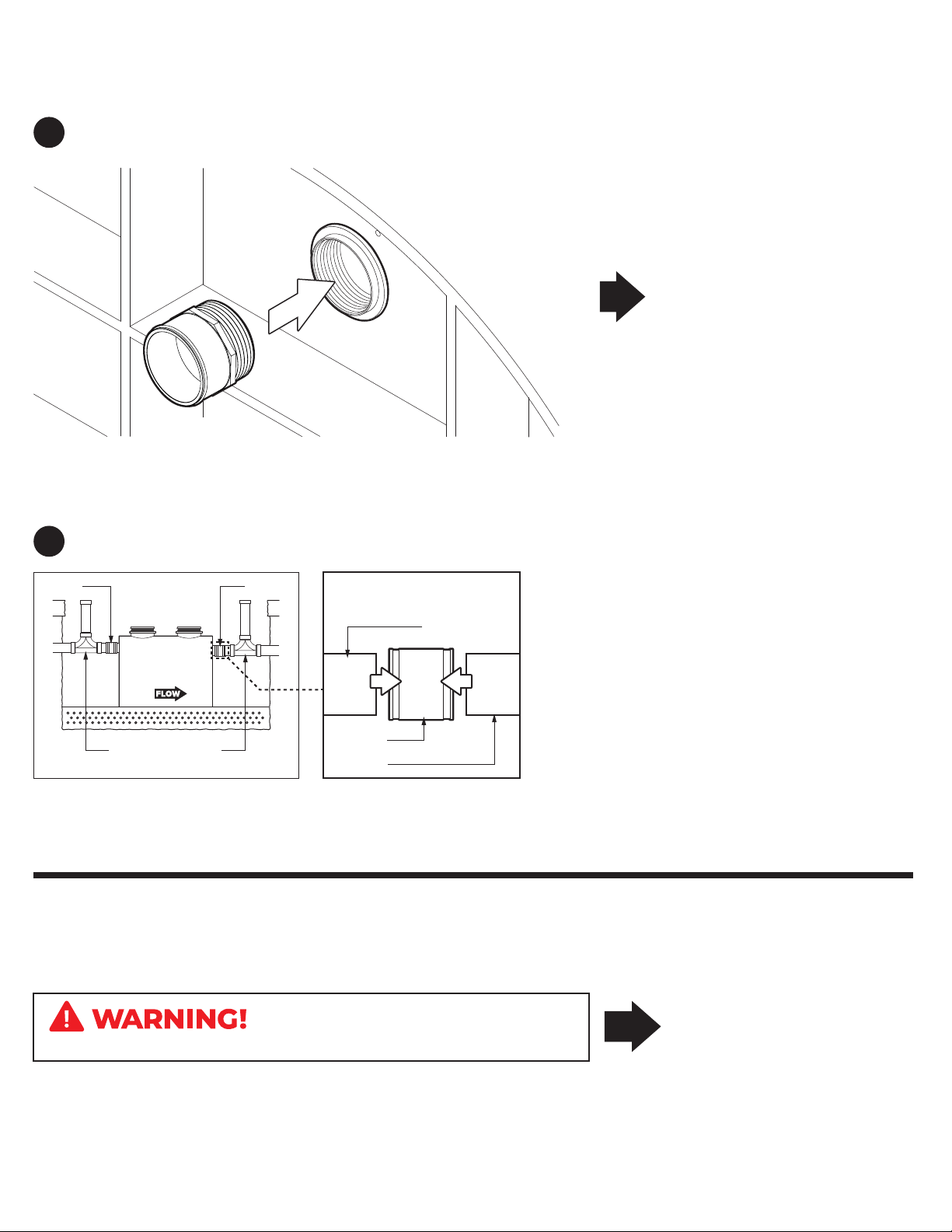
ODOR ALERT!
Interceptor is not a
sewer gas trap.
All upstream fixtures
must be trapped
concrete slab subject to hydrostatic pressure
watertight
concrete
vault
Hydrostatic/
Pressure Slabs
When installed under a
hydrostatic slab (slab
designed to withstand
upward lift, usually caused
by hydrostatic pressure)
interceptor must be
enclosed in a watertight
concrete vault.
SPECIAL PRECAUTIONS
Do not install this unit in any manner
except as described in these instructions.
Doing so may result in property damage, personal injury or death.
DO NOT AIR TEST UNIT OR RISER SYSTEM!
For Schier Grease Interceptor Installations - Failure to follow this guidance
voids your warranty
Schier | GB-1000-B Installation Guide
page 2 of 9