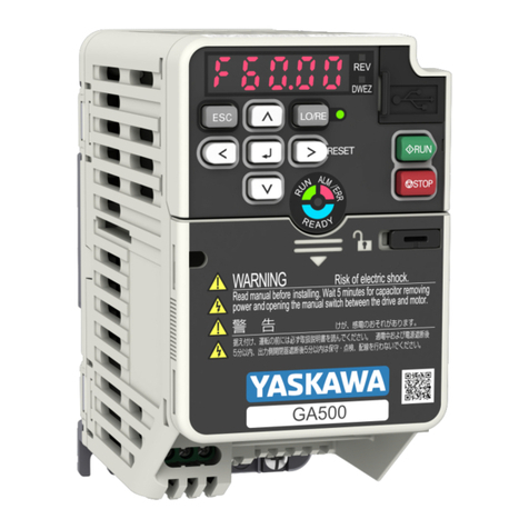
YASKAWA JVOP-KPLEA04A Series User manual

MANUAL NO. TOEP C730600 74D
YASKAWA AC Drive Option
LED Keypad
Installation Manual
Type: JVOP-KPLEA04Axx, JVOP-KPLEA04Mxx
To properly use the product, read this manual thoroughly and retain for easy
reference, inspection, and maintenance. Ensure the end user receives this
manual.

This Page Intentionally Blank
2YASKAWA TOEP C730600 74D LED Keypad Installation Manual

YASKAWA TOEP C730600 74D LED Keypad Installation Manual 3
Table of Contents
1. Preface and Safety. . . . . . . . . . . . . . . . . . . . . . . . . . . . . 5
Applicable Documentation . . . . . . . . . . . . . . . . . . . . . . . . . . . . 5
Glossary . . . . . . . . . . . . . . . . . . . . . . . . . . . . . . . . . . . . . . . . . . . 5
Registered Trademarks. . . . . . . . . . . . . . . . . . . . . . . . . . . . . . . 6
Supplemental Safety Information . . . . . . . . . . . . . . . . . . . . . . . 6
2. Overview. . . . . . . . . . . . . . . . . . . . . . . . . . . . . . . . . . . . . 7
3. Receiving . . . . . . . . . . . . . . . . . . . . . . . . . . . . . . . . . . . . 7
4. Component Names and Functions . . . . . . . . . . . . . . . . 9
LED Status Indicators . . . . . . . . . . . . . . . . . . . . . . . . . . . . . . . 12
5. Installation Procedure . . . . . . . . . . . . . . . . . . . . . . . . . 14
Section Safety . . . . . . . . . . . . . . . . . . . . . . . . . . . . . . . . . . . . . 14
Remote Operation . . . . . . . . . . . . . . . . . . . . . . . . . . . . . . . . . . 14
Methods to Install a Remote Keypad . . . . . . . . . . . . . . . . . . . 15
Option Dimensions . . . . . . . . . . . . . . . . . . . . . . . . . . . . . 17
Procedure A . . . . . . . . . . . . . . . . . . . . . . . . . . . . . . . . . . . 18
Procedure B . . . . . . . . . . . . . . . . . . . . . . . . . . . . . . . . . . . 27
6. Basic Operation . . . . . . . . . . . . . . . . . . . . . . . . . . . . . . 38
Keypad Display Function Hierarchy . . . . . . . . . . . . . . . . . . . . 38
Display Screens and Functions (Default Setting) . . . . . . . . . 39
Keypad Operation . . . . . . . . . . . . . . . . . . . . . . . . . . . . . . . . . . 42

4YASKAWA TOEP C730600 74D LED Keypad Installation Manual
Set Frequency Reference to Run/Stop . . . . . . . . . . . . 43
Monitoring Drive Status . . . . . . . . . . . . . . . . . . . . . . . . 44
Change Parameter Setting Values. . . . . . . . . . . . . . . . 45
Verifying and Changing Parameter Settings
(Verify Menu) . . . . . . . . . . . . . . . . . . . . . . . . . . . . . . . . . 46
Switching between LOCAL Mode and REMOTE
Mode . . . . . . . . . . . . . . . . . . . . . . . . . . . . . . . . . . . . . . . 48
Execute Auto-Tuning . . . . . . . . . . . . . . . . . . . . . . . . . . 48
Read Parameter Settings from the Drive
(Backup) . . . . . . . . . . . . . . . . . . . . . . . . . . . . . . . . . . . . 52
Write Parameters Saved in the Keypad to
Another Drive (Restore) . . . . . . . . . . . . . . . . . . . . . . . . 54
Verify Parameters in Drive and Parameters
Saved in Keypad (Verification) . . . . . . . . . . . . . . . . . . . 55
7. Related Parameters. . . . . . . . . . . . . . . . . . . . . . . . . . 57
8. Fault Diagnostics and Measures . . . . . . . . . . . . . . . 60
9. Disposal Instructions . . . . . . . . . . . . . . . . . . . . . . . . . 62
WEEE Directive. . . . . . . . . . . . . . . . . . . . . . . . . . . . . . . . . . . 62
10. Specification. . . . . . . . . . . . . . . . . . . . . . . . . . . . . . . . 63
11. Warranty. . . . . . . . . . . . . . . . . . . . . . . . . . . . . . . . . . . 64
Warranty Period and Scope . . . . . . . . . . . . . . . . . . . . . . . . . 64
About Application of This Product . . . . . . . . . . . . . . . . . . . . 65
Revision History . . . . . . . . . . . . . . . . . . . . . . . . . . . . . . . . . 66

1 Preface and Safety
YASKAWA TOEP C730600 74D LED Keypad Installation Manual 5
1 Preface and Safety
◆Applicable Documentation
Document Description
YASKAWA AC Drive
Option
LED Keypad
Manuals
Read this manual first.
The manual contains basic information required to
install and wire the keypad.
This manual is packaged with the keypad.
YASKAWA AC Drive
Manuals
For information about drive settings, refer to the
manuals for the drive on which you will use this kit.
The manuals provide information about basic
installation, wiring, operation procedures, functions,
troubleshooting, and maintenance.
The manuals also include important information
about parameter settings and tuning the drive.
You can download drive manuals from the Yaskawa
product and technical information website shown on
the back cover of this manual.
Note:
This manual shows typical examples. Different drive models can have different
functions. Refer to the drive manuals for more information.
◆Glossary
•Drive:
–YASKAWA AC Drive GA500
–YASKAWA AC Drive GA700
–YASKAWA AC Drive GA800
–YASKAWA AC Drive CR700
–YASKAWA AC Drive CH700
•Keypad: YASKAWA AC Drive Option LED Keypad

1 Preface and Safety
6YASKAWA TOEP C730600 74D LED Keypad Installation Manual
◆Registered Trademarks
Company names and product names mentioned in this manual are
trademarks of those companies.
◆Supplemental Safety Information
Read and understand this manual before you install, operate, or do
maintenance on the option. Use this option as specified by this
manual and local codes.
The symbol marks in this section identify safety messages in this
manual. If you do not obey these safety messages, the hazards can
cause serious injury, death, or damage to the products and related
equipment and systems.
DANGER This signal word identifies a hazard that will cause
serious injury or death if you do not prevent it.
WARNING This signal word identifies a hazard that can cause
death or serious injuries if you do not prevent it.
CAUTION Identifies a hazardous situation, which, if not avoided,
can cause minor or moderate injury.
NOTICE This signal word identifies a property damage message
that is not related to personal injury.
■General Safety
General Precautions
•The figures in this manual can possibly include options and drives without covers
or safety shields to show detail. Install missing covers or safety shields before
you operate the drive. Use the option only as specified by the instructions in this
manual.
•The diagrams in this manual are only examples and are not always related to all
the products included in this manual.
•Yaskawa can change the products and specifications in this manual or the content
and presentation of the manual without notice to improve the product and/or the
manual.
•If you damage or lose manuals, contact a Yaskawa representative or the nearest
Yaskawa sales office shown on the rear cover of the manual, and tell them the
document number on the front cover to order new copies.
2 Overview
YASKAWA TOEP C730600 74D LED Keypad Installation Manual 7
DANGER Do not ignore the safety messages in this manual. If you
ignore the safety messages in this manual, it will cause serious injury or death.
The manufacturer is not responsible for injuries or damage to equipment.
2 Overview
Connect the keypad option to the drive to perform the following
basic operations:
•Read or modify drive parameter settings
•Back up, restore, and verify drive parameters
•Operate and stop the drive
•Monitor drive operation status
Note:
This product has no clock function.
◆Compatible Products
Product Series Drive Software Version
*1
GA500 All
GA700 All
GA800 All
CR700 All
CH700 All
*1 Refer to "PRG" on the drive nameplate for the software version number.
3 Receiving
1. Make sure that the keypad is not damaged and no parts are
missing.
Immediately contact the shipping company if the option or
other parts are damaged. The Yaskawa warranty does not
include damage from shipping.

3 Receiving
8YASKAWA TOEP C730600 74D LED Keypad Installation Manual
2. Make sure that the model number on the option nameplate and
the model shown in the purchase order are the same.
Immediately contact the distributor where you purchased the
option or the Yaskawa sales office about problems with the
option.
◆Option Package Contents
Option Contents Quantity
LED Keypad 1
Instruction Manual 1

4 Component Names and Functions
YASKAWA TOEP C730600 74D LED Keypad Installation Manual 9
4 Component Names and Functions
Figure 4.1 Keypad Components
- Key and LED Function
A
RUN LED
Illuminates to show that the drive is operating the motor.
B
REV LED
Illuminates when a reverse Run command is active.
C
ALM LED
Illuminates when the drive detects a fault.
D
DRV LED
Illuminates when the drive is in Drive Mode.

4 Component Names and Functions
10 YASKAWA TOEP C730600 74D LED Keypad Installation Manual
- Key and LED Function
ELED Display
Panel
Displays data, parameters, and errors.
Note:
This manual uses radiating triangles to show flashing
digital characters on the keypad as in this figure:
F
LO/RE LED
Illuminates to identify when the drive is operating in
LOCAL Mode.
G
LO/RE
Selection Key
Switches drive control for the Run command and frequency
reference between the keypad (LOCAL) and an external
source (REMOTE).
Note:
•The drive will not switch between LOCAL Mode and
REMOTE Mode when it is receiving a Run command
from an external source.
•Stop operation to enable the LO/RE Selection Key
when in Drive Mode. Set o2-01 = 0 [LO/RE Key
Function Selection = Disabled] to disable
when switching from REMOTE to LOCAL will have
a negative effect on system performance.
H
STOP Key
Stops drive operation.
Note:
Push to stop the motor. This will also apply
when a Run command (REMOTE Mode) is active at an
external Run command source. Set o2-02 = 0 [STOP
Key Function Selection = Disabled] to disable
in REMOTE Mode.
I
RUN Key
Starts the drive in LOCAL Mode.
Note:
Push the LO/RE Selection Key on the keypad to set the
drive to LOCAL Mode before you use the keypad to
operate the motor.

4 Component Names and Functions
YASKAWA TOEP C730600 74D LED Keypad Installation Manual 11
- Key and LED Function
J
Left Arrow Key
Moves the cursor to the left.
Up Arrow Key/
Down Arrow
Key
/
•Scrolls up or down to show the next item or the previous
item.
•Selects parameter numbers and increments/decrements
setting values.
Right Arrow
Key (RESET) •Moves the cursor to the right.
•Clears drive faults.
ENTER Key •Enters parameter values and settings.
•Selects a menu item to navigate between displays.
K
ESC Key •Goes back to the previous display.
•Push and hold this key to go back to the Frequency
Reference display.
LCable
Connector
Connects to the drive using an RJ-45 8-pin straight through
UTP CAT5e extension cable or keypad connector.
M Nameplate
Shows the model number of the keypad and other
information
Note:
“REV”on the nameplate identifies the hardware and
software version of the keypad.

4 Component Names and Functions
12 YASKAWA TOEP C730600 74D LED Keypad Installation Manual
◆LED Status Indicators
LED State Drive Status
RUN LED
Illuminated The drive is operating the motor.
Flashing
•The drive is decelerating to stop.
•The drive received a Run command with a
frequency reference of 0 Hz while the drive is set
to a mode other than a control mode with zero
speed control.
•The drive received a DC Injection Braking
command.
Flashing
Quickly
•The drive received a Run command from the
external source and is switching to REMOTE
Mode while the drive is in LOCAL Mode.
•The drive received a Run command from an
external source and the drive is not in Drive Ready
(READY) condition.
•The drive received a Fast Stop command.
•The safety function shut off output.
•You pushed on the keypad while the
drive is operating in REMOTE Mode.
•The drive is energized with an active Run
command and b1-17 = 0 [Run Command at Power
Up = Disregard Existing RUN Command].
•The drive is set to coast-to-stop with timer (b1-03
= 3 [Stopping Method Selection = coast to stop
with timer]) with the Run command disabled, and
you activated the Run command during the Run
wait time.
•The drive received a DC Injection Braking
command.
OFF The drive stops.
REV LED Illuminated The drive received a reverse Run command.
OFF The drive received a forward Run command.

4 Component Names and Functions
YASKAWA TOEP C730600 74D LED Keypad Installation Manual 13
LED State Drive Status
ALM LED
Illuminated The drive detected a fault.
Flashing
The drive detected one of the following:
•A Minor fault, an alarm
•An oPE parameter setting error
•A fault or error during Auto-Tuning
Note:
The digital characters displayed on the keypad
will also flash.
OFF The drive is in regular operation without alarms or
faults.
DRV LED
Illuminated The drive is in Drive Mode.
Flashing
You are using DriveWorksEZ.
Note:
Refer to the DriveWorksEZ instruction manual
for details regarding DriveWorksEZ.
OFF The drive is in Programming Mode.
LO/RE LED Illuminated The keypad is selected for Run command control
(LOCAL).
OFF A device other than the keypad is selected for Run
command control (REMOTE).
■LED Flashing Statuses
Refer to Figure 4.2 and Figure 4.3 for information about the
differences between flashing and flashing quickly.
Figure 4.2 LED Flashing Statuses

5 Installation Procedure
14 YASKAWA TOEP C730600 74D LED Keypad Installation Manual
Figure 4.3 Relation between RUN LED and Drive Operation
5 Installation Procedure
◆Section Safety
NOTICE Damage to Equipment. Correctly connect all pins and
connectors. If the pins and connectors are incorrect, it can cause damage to
equipment and incorrect operation.
NOTICE Damage to Equipment. Do not bend the communication
cables more than the bend radius specifications. If you bend the cables too
much, it can break the wires and loosen connections.
Note:
Use Yaskawa connection cables or recommended cables only. Incorrect cables can
cause the drive or option to function incorrectly.
◆Remote Operation
You can remove the digital operator and use a 3 m (9.8 ft.) length
maximum extension cable to connect it to the drive. The option
makes it easier to operate the drive when you install the drive in a
location where you cannot easily access it. Contact Yaskawa or
your nearest sales representative to order optional accessories.
/

5 Installation Procedure
YASKAWA TOEP C730600 74D LED Keypad Installation Manual 15
◆Methods to Install a Remote Keypad
Installation Method Description Required Tools
External/Face-Mount
Installs the option on the
outside of the panel. An
optional installation bracket
is not necessary for this
installation.
Phillips screwdriver #2 (M3)
Internal/Flush-Mount
Encloses the keypad in the
panel. The front of the
keypad is flush with the
outside of the panel.
•Phillips screwdriver #2
(M3, M4)
•Installation support set A
(for mounting with
screws, model: 900-192-
933-001)
•Phillips screwdriver #2
(M3)
•Wrench (M4)
•Installation support set B
(for mounting with nut
clamp, model: 900-192-
933-002)
Note:
Installation support sets are sold separately. When there are weld studs on the
interior of the control panel, use installation support set B.
■Installation Procedure
The installation procedure is different for different drives.
Drive Procedure Page
GA700, GA800, CR700,
CH700
A18
GA500 B 27
■Optional Items
The optional extension cable and installation support set are
necessary for Internal/Flush-Mount installation.

5 Installation Procedure
16 YASKAWA TOEP C730600 74D LED Keypad Installation Manual
Contact Yaskawa or your nearest sales representative to order
optional items.
Item Part
Number Notes
Extension cable
(1 m (3.3 ft.)) WV001 *1
Connects the keypad for remote
operation.
•RJ-45 8-pin straight through
•UTP CAT5e cable (1 m (3.3 ft.)/3 m
(9.8 ft.))
NOTICE Damage to
Equipment. Do not use this cable to
connect the drive to a PC. Failure to
obey will cause damage to the PC.
Extension cable
(3 m (9.8 ft.)) WV003 *1
Installation support set A
(screw clamp)
900-192-
933-001
Encloses the keypad in the panel.
•M3 screws: 6 mm (0.24 in.) depth
Phillips recessed pan head machine
screws (2)
•M4 screws: 10 mm (0.39 in.) depth
Phillips truss head screws (4) (for
panel thickness of 1 to 1.6 mm (0.04
to 0.06 in.))
Installation support set B
(nut clamp)
900-192-
933-002
Encloses the keypad in the panel.
When there are weld studs on the interior
of the control panel, use the installation
support set B (nut clamp).
•M3 screws: 6 mm (0.24 in.) depth
Phillips recessed pan head machine
screws (2)
*1 Part numbers for the U.S.A. are UWR0051 and UWR0052. Contact Yaskawa
or your nearest sales representative for more information.

5 Installation Procedure
YASKAWA TOEP C730600 74D LED Keypad Installation Manual 17
■Option Dimensions
Figure 5.1 Dimensions
Table 5.1 Dimensions mm (in.)
W H D D1 D2 R *1 W1 W2 H1 d
65
(2.56)
106
(4.17)
16
(0.63)
8.2
(0.32)
1.6
(0.06)
≥ 53.8
(2.12)
44
(1.73)
15
(0.59)
78
(3.07) M3
*1 Minimum bending radius
NOTICE Damage to Equipment. Do not bend the communication
cables more than the bend radius specifications. If you bend the cables too
much, it can break the wires and loosen connections.

5 Installation Procedure
18 YASKAWA TOEP C730600 74D LED Keypad Installation Manual
■Procedure A
External/Face-Mount Installation
1. Use the dimensions in Table 5.2 and Figure 5.2 to cut an
opening and tap two holes in the enclosure panel.
Figure 5.2 External/Face Mount Enclosure Panel Cut-Out
Dimensions
Table 5.2 Enclosure Panel Cut-Out Dimensions mm
(in.)
W H W1 H1 H2 H3 d
22
(0.87)
78
(3.07)
22
(0.87)
29
(1.14)
22
(0.87)
1
(0.04)
3.6
(0.14)

5 Installation Procedure
YASKAWA TOEP C730600 74D LED Keypad Installation Manual 19
2. Use M3 screws (6 mm (2.4 in) depth cross-recessed pan
head screws) to attach the keypad from the inside as
shown in Figure 5.3.
A - Keypad
B - M3 screws
C - Enclosure panel
D - Screw mounting
holes
Figure 5.3 External/Face-Mount Installation
3. Push the tab on the top of the drive keypad and carefully
pull forward to remove the keypad from the drive.
Figure 5.4 Removing the Included Drive Keypad
This manual suits for next models
1
Table of contents
Other YASKAWA Keypad manuals

YASKAWA
YASKAWA JVOP-KPLCD04AxB User manual

YASKAWA
YASKAWA JVOP-180 User manual

YASKAWA
YASKAWA 900-239-230-001 User manual

YASKAWA
YASKAWA JVOP-KPLCB04AxB User manual

YASKAWA
YASKAWA JVOP-KPLCC04A Series User manual

YASKAWA
YASKAWA JVOP-KPLCA04A Series User manual

YASKAWA
YASKAWA JZSP-GA500 User manual

YASKAWA
YASKAWA JVOP-KPLCC04A Series User manual