4
If any components are missing, contact Scientifica in the UK or your local
representative. Save the special carton for future storage or transportation of the
LBM-7 Manual manipulator.
2.2.1 Quality Control
Each LBM-7 Manual manipulator undergoes many stages of inspection, including a
pre-shipment burn-in. It is designed for years of trouble-free operation. In the unlikely
event that problems occur, please contact Scientifica in the UK or your local
representative for instructions. Our Customer Service team are ready to help with
advice, parts and repair services.
3. INSTALLATION
Correct mounting is essential for providing good system performance. It is important
that the mounting system be mechanically and thermally stable, whilst providing
flexibility for different experimental set-ups.
3.1. Installing the Microscope Mount
Scientifica recommends using a microscope mount that attaches directly to the
user’s microscope or a post and platform style mount. These methods provide
excellent stability and convenience.
3.1.1. Universal Post and Platform Mount (Optional)
The Post and Platform is available as an alternative to the microscope mounts. This is a
universal solution and particularly useful for upright microscopes. It can be secured to
the top surface of the isolation table either directly or via a magnetic base.
Two options are available:
Model Description
PCS-500-MD11 Universal Post and Platform with Magnetic Base
PCS-500-MD12 Universal Post and Platform without Magnetic Base
Please note that because the post is mounted separately from the microscope, it is
important for the microscope to be rigidly mounted to the same surface as the post
mount. This may require modification to the microscope, for example, removing the
rubber feet, and/or clamping the microscope to the base plate. If this is not carried out
then the two items may move in relation to one another and drift may be apparent.
3.2. Mounting the LBM-7 Manual manipulator to your Microscope
Mount
The LBM-7 Manual manipulator is compatible with both metric and imperial sized
through patterned holed mounts.
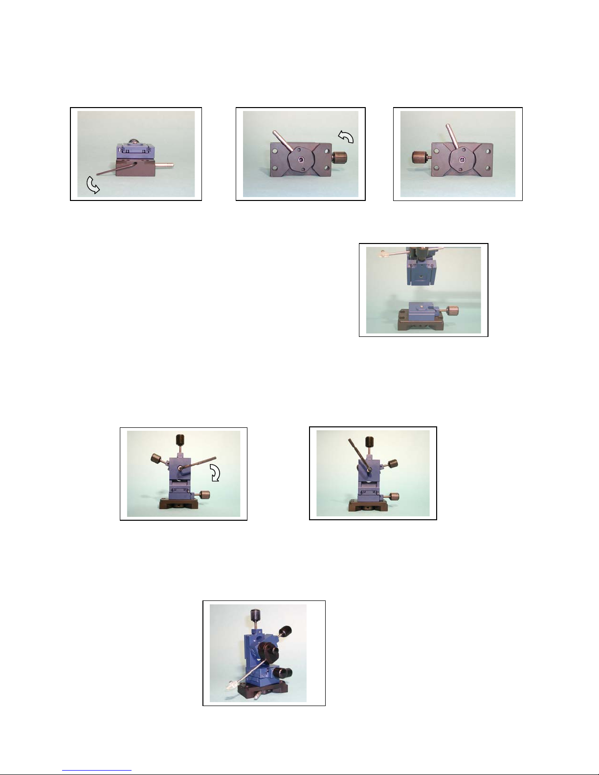
3.3. Configuring the LBM-7 Manual manipulator
The symmetrical design of the LBM-7 Manual manipulator makes it easy to
configure for right-sided operation (Section 3.3.1) or left-sided operation (Section
3.3.2) without the need for any adapter kits.
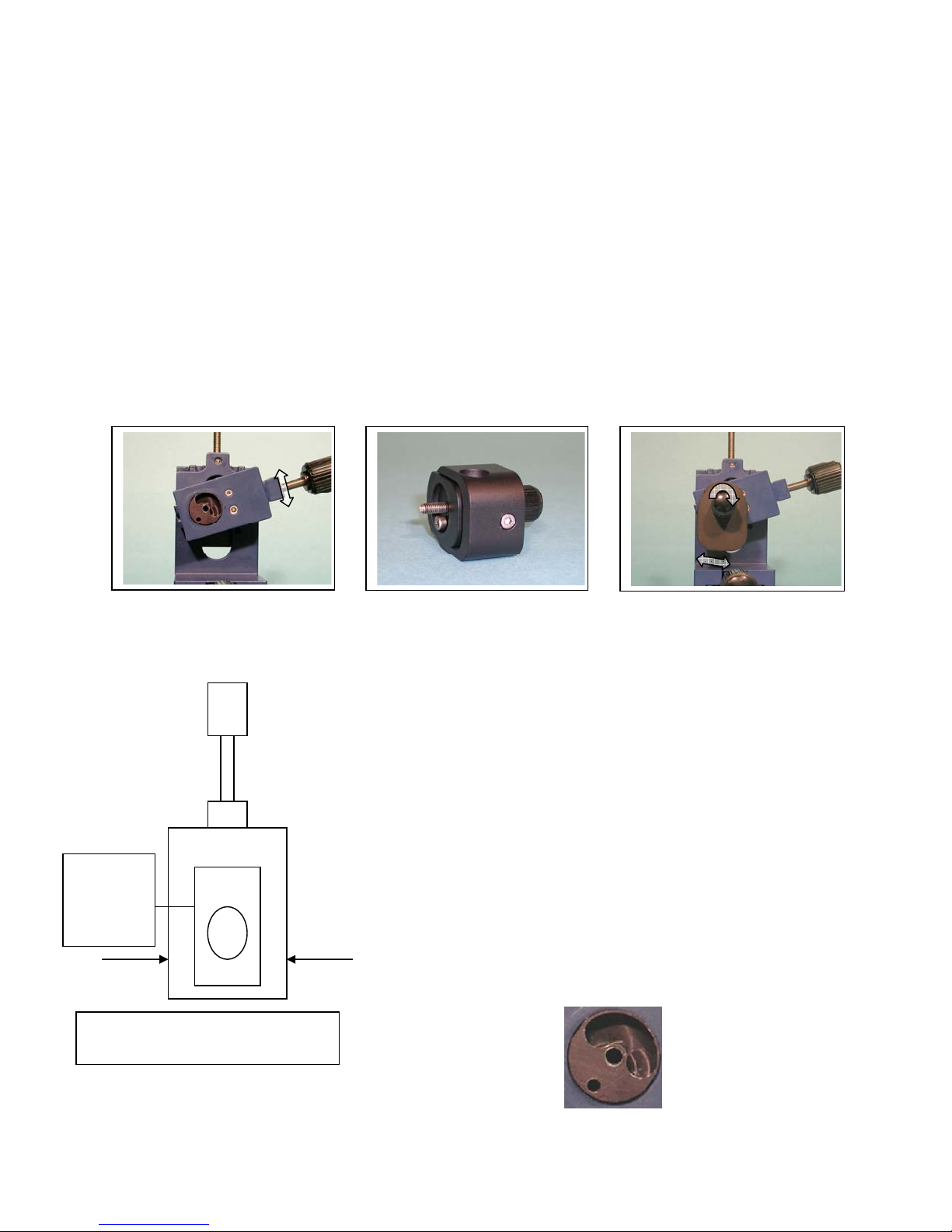
CAUTION: Do not tighten, loosen or remove any of the bearing adjustment screws
on the side of each stage otherwise the manipulator will need to be returned to
Scientifica for adjustment or reassembly. This is not covered under warranty.