Scientifica Multiphoton Scanhead Manual instruction

Multiphoton
Scanhead
Setup and operation manual
Revision 1.0
Manual Part No.: 2P-Scanner MANUAL

© Scientifica Ltd
1A Kingfisher Court, Brambleside, Bellbrook Industrial Estate,
Uckfield, TN22 1QQ, United Kingdom
Tel +44 (0) 1825 749 933
Fax +44 (0) 1825 749 934
info@scientifica.uk.com

Contents
Note: This manual describes the features, functions and operation of
the Scientifica Multiphoton Scanhead. Before use, please carefully read
this manual, directions for all accessories, all precautionary information
and specifications.
1.0 Product Introduction .......................................................................1!
1.1 Handling Scientifica equipment – precautions...............................1!
1.2 The Scientifica Scanhead ..............................................................2!
1.2.2 Product overview ....................................................................2!
1.2.3 Systems components .............................................................3!
1.2.3 Product walkthrough ...............................................................5!
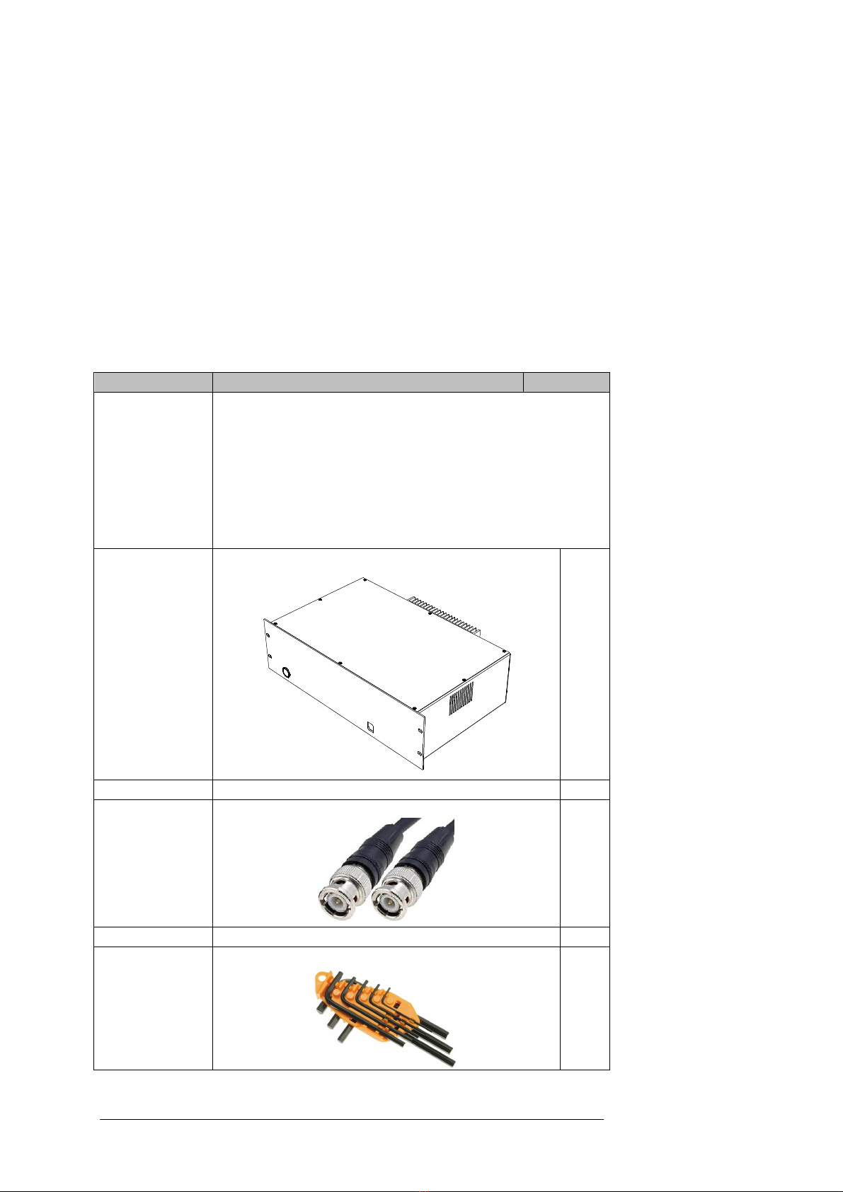
2.0 Packing List......................................................................................6!
2.1 Standard items...............................................................................6!
2.2 Optional items................................................................................7!
2.2.1 Alignment Pack contents ........................................................9!
3.0 Initial Setup ....................................................................................10!
3.1 Mechanical setup of the Scanhead..............................................10!
3.1.1 Removing the shipping brackets...........................................10!
3.1.2 Mounting and configuring the SliceScope microscope .........10!
3.1.3 Fitting a fluorescence turret to the Scanhead .......................10!
3.2 Electrical setup of the Scanhead .................................................12!
3.2.1 3U Control Rack ...................................................................12!
3.2.2 Electrical setup .....................................................................14!
3.2.3 Parameters for Scanhead electrical setup............................16!
3.3 Optical setup of the Scanhead.....................................................17!
3.3.1 Positioning the launch optics ................................................17!
3.3.2 Checking the alignment of the Scanhead galvanometers ....18!
3.3.3!Aligning the laser to the Scanhead ..................................20!
4.0 Operation Guide.............................................................................21!
4.1 Software control of the Scanhead................................................21!
4.2 Powering up the system ..............................................................21!
4.3 Operating the Scanhead..............................................................21!
4.3.1 Standard operation ...............................................................21!
4.3.2!Alternative visualisation and imaging techniques.............22!
5.0 Maintenance ...................................................................................23!
5.1 Cleaning.......................................................................................23!
6.0 Troubleshooting ............................................................................24!
6.1 No movement of the galvos .........................................................24!
6.2 Misalignment of the laser to the Scanhead..................................24!
7.0 Specifications ................................................................................25!
Appendix 1.0 ........................................................................................26!
1.1!Electrical configuration with shutter control.............................26!
1.2 System electrical connections checklist.......................................28!
1.2.1 Configuring the spring terminal block ...................................30!
8.0 Warranty, Technical Queries and Returns ..................................31!
9.0 About Scientifica ...........................................................................31!


1.0 Product Introduction |1
1.0 Product Introduction
1.1 Handling Scientifica equipment – precautions
This section contains important safety information related to general use
of the Scientifica Scanhead. It is a piece of scientific equipment and as
such requires care when handling.
• Before use, carefully read the instructions, including all
warnings and cautions.
• Inspect the product, any cables, and connectors before each
use.
• Do not use any equipment that appears damaged.
• Do not apply excessive tension to any cable.
• There are no user serviceable parts inside the unit.
• Always disconnect the instrument from the power supply prior
to cleaning the system or performing maintenance work.
Adjustment or removal of any screws or components
other than those noted in this manual can adversely
affect the performance and operation of your device and
may invalidate your warranty.
The Scanhead requires a dangerous class IV infrared
pulsed laser product, which produces hazardous,
invisible laser radiation that can permanently damage
your eyes. It is therefore, strongly advised that the
correct Personal Protective Equipment is used when
handling. Please consult your laser manufacturer or the
laser manual for more details.
Alignment of the class IV laser into the Scanhead should
always be done at minimum power and the wavelength
of the laser tuned into the edge of the visible range. This
is in order to minimise output from the laser and reduce the
efficiency of mode-locked pulsed operation. Some laser
manufacturers also provide an alignment mode, which
operates the laser at safer output powers.
Never switch the top diagonal mirror of the Scanhead when
scanning or aligning as this will cause the beam to be
reflected and exit back out of the input port. Never look
down eyepieces when scanning or aligning as this may
result in eye damage.

2| 1.0 Product Introduction
1.2 The Scientifica Scanhead
1.2.2 Product overview
The Scientifica Scanhead is optimised for the diffraction limited X Y
raster scanning of infrared radiation (700-1100 nm) across a biological
specimen. The two scan axes are provided by two high speed
galvanometer scanners (galvos) operating at a maximum scan angle of
±7.6 degrees up to scan rates of 1 kHz. This scan angle approximates
to a field of view of ~±200 µm, when using a 40×microscope objective.
There are two available input ports to the Scanhead on the left and right
side of the lower scan assembly housing the X galvo scanner. The input
beam diameter is limited by the 3 mm ×5 mm mirrors fitted to the
galvanometer scanners.
A unique feature of the Scanhead, which limits the amount of beam
wobble on the back aperture of the objective, is an optimised set of relay
lenses. The relay lenses are situated vertically in a beam tube between
the x and y galvos.
Once the beam of light has passed through the relay lenses it is directed
along a 3.5x beam expander, which sits horizontally under the top cover
of the Scanhead. This serves to fill the back aperture of the objective to
a diameter 10.5 mm for a 3 mm input beam.
The last optic of the Scanhead is the switchable top diagonal turning
mirror used to switch between laser scanning and widefield camera
imaging.

1.0 Product Introduction |3
Figure A: Light path of the Scientifica Scanhead
Typically the Scientifica Scanhead is supplied as part of a complete
Multiphoton Imaging System. If this is the case the Scanhead will be
shipped pre-attached to the Slicescope microscope, often along with
components for attaching optical elements and Scientifica’s Multiphoton
Detection Unit (MDU).
The Slicescope is a fully motorised, nose-focusing microscope
compatible with industry-standard Olympus optics, for various
experimental applications used in electrophysiological work (see
separate SliceScope manual for further information).
1.2.3 Systems components
As a stand-alone item the Scanhead consists of four main assemblies,
designed to fit onto Scientifica’s SliceScope:
X galvo assembly: Contains galvanometers for X mirror scanning,
featuring locking set screw and dimple for alignment with 2 mm hex key.
Relay lens assembly: Grips the stainless steel column of the
Slicescope and features a clamping plate for attaching the relay lens
tube. The relay lens tube contains lenses that image the X galvo mirror
1:1 onto the Y mirror.
Y galvo assembly:Contains galvanometers for Y mirror scanning.
Features locking set screw and dimple for alignment with 2 mm hex key.

4| 1.0 Product Introduction
Beam expander assembly and top plate
This module contains:
•A switchable diagonal mirror: a lever operated mirror for
switching between laser scanning and widefield camera
acquisition. This mirror can be customised with a dichroic for
specialised user requirements.
•A beam expander tube: containing lenses to expand the beam
3.5 times, onto the back aperture of the microscope objective.
Camera imaging port: The top of the Scanhead features a camera
imaging port with pre-attached adapter ring (this can be removed when
attachment of a fluorescence turret is also required). The adapter ring
accepts dovetail mount attachments, allowing you to attach Scientifica’s
tube lens or a standard Olympus tube lens to the top of the Scanhead.
The tube lens would be secured in place using the grub screw tightening
on the side of the adapter ring- see section 3.1.3 Fitting a fluorescence
turret to the Scanhead for full details.

1.0 Product Introduction |5
1.2.3 Product walkthrough
Figure B: SliceScope frame and Scanhead, with key assemblies indicated
Beam expander
assembly
Laser input
aperture
SliceScope Z-stage
connection port
Bright field
illumination port
Mounting points
Diffusion
lens lever
Achromatic
lens
Field iris
control
Turning mirror
lever
Camera imaging
port
Relay lens
assembly
Y galvo
assembly
X galvo
assembly

6| 2.0 Packing List
2.0 Packing List
When the system is first received carefully remove and identify all of the
components as listed below. If any of the items are missing, contact
Scientifica Ltd or your local distributor. Please retain the packaging for
storage or future transportation of the system.
In the unlikely event of the shipping packaging being damaged, notify
your shipping department immediately. The shipping department may
wish to notify the carrier at this point.
2.1 Standard items
Quantity
Part No.
1
Scanhead assembly, including:
•X Galvanometer assembly
•Relay lens assembly
•Top Cover
•Y Galvanometer assembly
Note: This may be shipped either assembled onto the Scientifica
SliceScope frame or as a stand-alone device for after-sale
attachment to a SliceScope.
1
3U rack mounted galvo controller
1
Mains lead for the 3U rack, locale specific
2
BNC-BNC cable
1
Screw kit (contents as per label inside lid)
1
Hex key set

2.0 Packing List |7
1
Setup and Operation Manual
Please consult the SliceScope Pro manual for items shipped specifically
for use with the SliceScope microscope.
2.2 Optional items
Part No.
Laser splitting module
Enables the laser beam to be split into two paths, for sharing one
source between two multiphoton microscopes.
MP-4500
Alignment Pack
Required to ensure correct alignment of the laser through the
Scientifica Scanhead for optimal system performance
CCD camera
Tube lens
IR card
Ground glass disc
Condenser arm (typically shipped with SliceScope)
Green LED illuminator with graticule
Projection lens with graticule
Iris
MP-4900
Launch optics, intensity control and shutter
Includes all relay optics to deliver the laser beam from the source into
the periscope optics. For use without Pockels cell control
Periscope optics
Motorised intensity control and beam dump
Table optics for beam steering
Power meter
Mechanical shutter
MP-4000
Launch optics and shutter
Includes all relay optics to deliver the laser beam from the source into
the periscope optics. For use with Pockels cell control
Periscope optics
Table optics for beam steering
Power meter
Mechanical shutter
MP-4400
Multiphoton workstation (for use with Pockels cell
control)
Data acquisition board, PC and interface rack to control the Scanhead
and image acquisition.
National Instruments 2090A BNC breakout box
National Instruments EP shielded cable (68-68 pin)
National Instruments EPM shielded cable (for
connecting Pockels cell to PCI-e board)
PC with monitor
National Instruments 6110 PCI-DAQ board
National Instruments PCIe-6321 board
Note: both PCI boards are pre-installed into the PC
MP-4700
Multiphoton workstation
Data acquisition board, PC and interface rack to control the Scanhead
and image acquisition.
National Instruments 2090A BNC breakout box
National Instruments EP shielded cable (68-68 pin)
MP-4800

8| 2.0 Packing List
PC with monitor
National Instruments 6110 PCI-DAQ board
Note: the PCI board is pre-installed into the PC
Fluorescence adapter kit
For fitting standard Olypmus fluorescence illuminator
turret
SS-3000-
30

2.0 Packing List |9
2.2.1 Alignment Pack contents
1a
CCD camera
1b
CCD camera USB cable
2a
Mount for tube lens and camera
2b
Tube lens
3a
LED intensity controller
3b
LED
3c
LED power supply
4
Ground glass disc
5
IR card
6
Projection lens with graticule
7a
Iris
7b
Iris with 1”-1/2” adapter

10|3.0 Initial Setup
3.0 Initial Setup
3.1 Mechanical setup of the Scanhead
The Scanhead is usually shipped already built around the SliceScope
microscope.
Please remember: adjustment or removal of any
screws or components other than those noted in this
manual can adversely affect the performance and
operation of your equipment and may invalidate your
warranty.
If you are unsure of the components discussed here, please review the
schematic in section 1.2.3.
Carefully remove the assembly from the packaging and place it
on your anti-vibration surface. When lifting, grip the column of
the SliceScope frame firmly. Do not hold the assembly using the
lower stage optics or any of the Scanhead components.
3.1.1 Removing the shipping brackets
The SliceScope frame and any translation devices included in the
system will be shipped with red brackets to prevent component damage
in transit.
Before proceeding, remove the red shipping brackets from the base of
the SliceScope using the supplied hex key set.
Important: Retain these brackets and screws for
future transit or return of the equipment. Component
damage is highly likely if these are not fitted during
shipping.
3.1.2 Mounting and configuring the SliceScope microscope
A Scientifica engineer will install the system on site and will configure
the Scanhead according to your specifications . There are individual
manuals available for all other Scientifica equipment. Please consult the
separate SliceScope Pro operation manual to configure the SliceScope
microscope frame.
There are also individual manuals available describing setup of imaging
platforms including; UMS, MMBP, MMTP.
3.1.3 Fitting a fluorescence turret to the Scanhead
Scientifica’s Multiphoton Imaging System has the provision for widefield
fluorescence to be carried out without removal of the Scanhead.

3.0 Initial Setup |11
When fitting the Olympus BX-RFA or BX-URA fluorescence illuminator
to the Scanhead, a Fluorescence Adapter Kit (Scientifica PN: SS-3000-
30) is required.
1. Remove the ring adapter from the top of the Scanhead, using
the four screws securing it in place.
2. Place the fluorescence adapter bracket on top of the
Scanhead. The curved end of the uprights should be towards
the front of the SliceScope (the square edges will be
positioned at the rear).
3. Be sure to align the four holes on the adapter bracket with
the tapped holes on the beam expander assembly.
4. Carefully remove the four plastic screw covers from the top
surface of the fluorescence illuminator.
5. Place the fluorescence illuminator on top of the adapter
bracket, ensuring that its holes are aligned with those on the
adapter bracket and imaging shelf. Secure in place by
tightening the captured screws using the 4 mm hex key
supplied.
Figure C: Fitting a fluorescence turret to the Scanhead

12|3.0 Initial Setup
3.2 Electrical setup of the Scanhead
Caution: Never connect or disconnect any cables with
the 3U Control rack switched on.
To operate as a system the Scanhead will require connecting to a 3U
driver rack, which is controlled by a PC workstation via a BNC breakout
box.
Please note that the wiring configuration may vary, depending on other
equipment in the setup and the control and acquisition system being
used. For more information on software specific wiring requirements,
please consult the user guides of your software package (eg.
HelioScan,ScanImage).
3.2.1 3U Control Rack
The 3U control rack will be factory configured with two control boards,
one for each galvanometer mirror. As these control boards are
preconfigured to be used with their respective galvanometers, be sure to
connect these correctly, as per the labelling on the rear panel of the 3U
rack. The 120 inch flying leads from each mirror feature a 9pin D-type
connector, which should be connected to the ports marked ‘Galvo X’
and ‘Galvo Y’ respectively.
Note: Control racks are preconfigured for use with the supplied
scanner. Therefore reconfiguration is unnecessary. If you need
to alter your setup, please contact Scientifica.
The command voltage for each galvanometer is fed to their respective
board by two BNC bulkhead connectors at the rear of the rack. These
are marked ‘X-drive’ and ‘Y-drive’ respectively and the supplied BNC
cables should be used.
Figure D: Rear panel of the 3U Rack mounted controller

3.0 Initial Setup |13
A
Xcommand (galvo position) signal input – BNC connector
B
Xgalvanometer board connection - 9-pin D-type connector-
supplying control signal and feedback
C
Ycommand (galvo position) signal input – BNC connector
D
Ygalvanometer board connection - 9-pin D-type connector -
supplying control signal and feedback
E
AC mains input and fuse

14|3.0 Initial Setup
3.2.2 Electrical setup
1. Complete the electrical setup of the SliceScope, translation
system and control system
Connect motorised translation stages and the SliceScope Z
stages to the 1U racks and control devices. Detailed information
about connecting and configuring the 1U racks can be found in
the SliceScope Pro operation manual.
2. Connect the Galvanometer mirrors to the 3U driver rack
The Scanhead features two dual tone flying cables, one driving
each of the two galvanometer mirrors. Connect the lower and
upper of these cables to the rear panel of the large 3U rack, into
ports marked “Galvo X” and “Galvo Y” respectively.
3. Connect the 3U driver rack to the National Instruments BNC-
2090A (or alternative control system supplying command
voltage)
The rear panel of the 3U rack features two BNC ports marked 'X-
drive' and 'Y-drive'. Using a BNC cable, connect the X-drive to
the analog output AO0 port and the Y-drive to the analog output
AO1 port on the BNC-2090A.

3.0 Initial Setup |15
Figure E Simple electrical configuration

16|3.0 Initial Setup
3.2.3 Parameters for Scanhead electrical setup
The Scanhead can be integrated with a range of scanning control and
data acquisition systems. The driver boards that control the
galvanometers can accept a position control voltage input in the range
of +/- 10 V. The optical design of the Scanhead allows for maximum
scan angles of +/- 7.6 degrees at a scale factor of 0.25 V per optical
degree resulting in a maximum range of +/- 1.9 V for typical applications.
Table of contents
Other Scientifica Laboratory Equipment manuals

Scientifica
Scientifica MMBP Manual instruction

Scientifica
Scientifica IVM Manual instruction

Scientifica
Scientifica LBM-7 User manual

Scientifica
Scientifica MDU Manual instruction

Scientifica
Scientifica SliceMate User manual

Scientifica
Scientifica MMTP User manual

Scientifica
Scientifica UMS Manual instruction

Scientifica
Scientifica MTP Guide
Popular Laboratory Equipment manuals by other brands

Velp Scientifica
Velp Scientifica AREX DIGITAL PRO F20500410 instruction manual

CAB
CAB A1000 Operator's manual

Miele
Miele PG8582 CD Installations plan

Endress+Hauser
Endress+Hauser Analytik Jena APU 28 Series operating instructions

Agilent Technologies
Agilent Technologies 6890 Series operating manual

Controls
Controls 58-C0181/DGT instruction manual