Scientifica SliceMate User manual

1
SliceMate Manual

2
The SliceMate
Introduction
The SliceMate provides temperature-controlled perfusion fluid to slice preparations
required during analysis of electrophysiological properties. Originally developed as
a modular sub-system for use with our unique SliceMaster – multi-channel
recording system, the SliceMate is a novel design integrating what would normally
be several separate sub-systems into a single line replaceable unit providing a
robust, space efficient system.
SliceMate Design
The SliceMate housing integrates the tissue bath, heat exchanger / Peltier device
and fluidic control valve within a dedicated Acetyl enclosure. The compact and
precision design ensures system variables are minimised and that all SliceMates are
identical in structure.
Tissue Bath
The brain bath has been developed to include features that simplify the
equipment table requirements; vacuum suction ports, integrated reference
electrode, thermistor temperature sensor and connectorized interface. The brain
bath puck is replaceable as a modular component. The thermistor temperature
sensors are precision devices which only require basic re-calibration if the brain
bath or thermistor should require replacement.

3
Heat Exchanger and Peltier Device
The heat exchanger has been developed for efficient transfer of heat energy to
the flowing perfusion fluid. The design is compact, containing a similar length of
tubing as alternative water bath systems thereby retaining comparable heat
density reducing risk of fluidic gassing. The body of the heat exchanger is
manufactured from aluminium, providing excellent heat transfer characteristics.
The polyethylene tube is pressed into the exchanger in a coiled form; the precision
“U” groove ensures tube retention during assembly. The low thermal mass of the
heat exchanger enables the system to heat rapidly and respond to control
demands much more quickly than water bath systems.
The Peltier device is used to transfer heat to and from the heat exchanger; the
device provides a large flat surface area to interface the thermal surfaces. The
heat exchanger assembly is mounted directly to the Stainless Steel ground plane
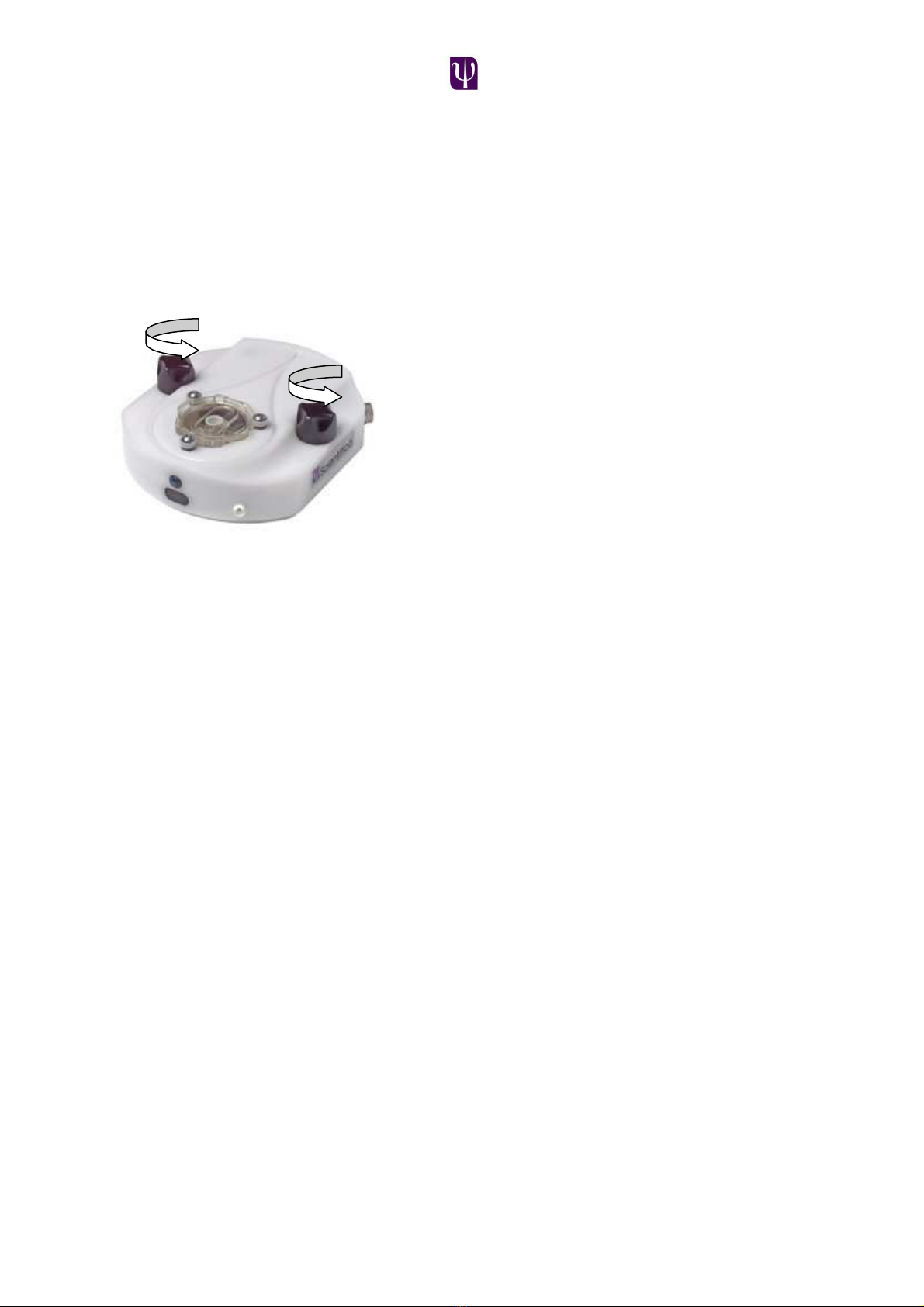
of the SliceMate. The heat exchanger spiral is held in position by a stainless steel
spring clip; this ensures the heat exchanger has ideal contact with the Peltier
device when the system is assembled.
System Screening
The SliceMate is grounded via the thermal control board and power supply, this
connects to the rig's star ground point (clean earth). The SliceMate is insulated
from the table to eliminate potential ground loops. A heavy duty Stainless Steel
ground plane has been included within the SliceMate to minimise the effects of
system and ambient noise. In our experience no additional screening of the system
is normally required although in high electrical noise environments the use of a
Faraday cage may be necessary.
System Connections
Waste Vacuum Port
The outlet port or 'waste vacuum port' interfaces to a 3.2mm internal diameter
silicon waste tube carrying waste to a high volume solution waste trap. The internal
heat exchanger waste tube is manufactured from stainless steel; it is grounded
within the SliceMate reducing electrical noise induced by the vacuum suction. The

4
vacuum must provide a continuous regulated suction within the specification
limits.
Perfusion Fluid Inlet Port
The 'perfusion fluid inlet port' interfaces via a barbed connector using 3.2 mm OD,
1.6mm ID Tygon tube from the drug delivery system. Tube connections to the drug
/ control selection system must be kept to minimal length to reduce dead volume;
the tubes should also be of similar lengths.
Digital control and sensor lines
The 16 pin electrical connector enables control and communication of the
SliceMate to the 19” rack mounted controller. The SliceMate is supplied with a
custom power / signal cable that interfaces to the SliceMate thermal control
system. The connectors should be fully mated to provide a low resistance earth
bond via the connector shells.
Reference Electrode Ground
The 'reference electrode ground' is located in between the primary well and the
suction port in the brain bath. The head-stage connects to the earth via the 2mm
white socket at the front of the SliceMate using the earth lead.
Installation
Visual Inspection
The Scientifica SliceMate and controller should reach you having been completely
protected during shipping. If the outside of the shipping packaging is damaged,
notify your shipping department immediately. The shipping department may wish
to notify the carrier at this point.
If the packaging is undamaged externally, carefully remove and identify all of the
components listed below:
•Thermal controller (1U rack mountable unit)
•SliceMate
•Cables - Thermal controller interface cable,
USB cable and AC power cord.
•Control Software CD
•Accessory kit
•Operating manual
Initial setup and test

5
The SliceMate should ideally be sited on a stable vibration isolated table. The base
plate accommodates mounting on either 25mm or inch hole spaced table
surfaces.
For safety during transit, the SliceMate is shipped as one assembly. In order to
mount the SliceMate first unscrew the two black Acetyl knobs and lift the
SliceMate from its base plate.
The base plate can now be sited as required and screwed down using the 4
button headed screws which can be found in the accessory kit. These are either ¼
x 20 x ¾” screws if using an inch table or, M6 x 20mm if metric.
Now locate the SliceMate onto the base plate and screw down the Acetyl knobs
to secure the assembly.
Setting up the fluid delivery.
The system can be used with either a gravity fed or pumped system. The system is
designed to operate over a flow rate range of 1 to 10 ml/ minute. The fluid should
be delivered to the SliceMate using tygon (or similar) tubing with an internal
diameter of 1.6mm (1/16”). If the fluid is to be pumped Scientifica recommend the
use of a fluid break in order to minimize pulsation effects.
Minimizing bubbles
It is suggested that the solutions to be used should be pre-heated. This is generally
done by placing gassing flasks of the solution in a water bath set at approximately
5ºC higher than the desired SliceMate bath temperature. The solution is then
transferred to the perfusion vessels prior to starting the experiment.
The theory is that although the solution is being gassed it should outgas at the pre-
heated temperature and as it never gets hotter than the pre-heated temperature

6
whilst passing through the heat exchanger bubbles are minimized. In order for this
to work the solution should be held in a vessel closed to air and supplied with
95/5% O2/CO2 reservoir. The diagram below shows a typical vessel setup. In this
case the vessel is securely mounted at the desired height and the head of pressure
is determined by the height of the lower end of the central glass tube. This ensures
that the flow rate remains constant throughout the entire experiment.
Setting up the vacuum.
The bath solution height is maintained and adjusted using the vacuum wicking
method. The SliceMate bath has a pair of oval suction vents which are connected
to the outlet port at the rear of the SliceMate. A typical vacuum/waste setup uses
either house vacuum or a suitable pump which is connected to a waste container,
which is in turn connected to the outlet port at the rear of the SliceMate.
The wick is made from filter paper which is cut into the shape shown below. The
wick is cut with a “V” at the one end of it. As the wick is moved back and forth
over the oval outlet ports the level of suction can be varied. This allows the user to
control the meniscus level above the bath.

7
System Operation
Flow control is controlled by triggering the proximity sensor at the front of the
SliceMate. This requires a continuous obstruction for more than one second; the
system will then switch between on and off.
The SliceMate displays proximity sensor (and valve) activation by illuminating or
de-illuminating the blue status LED at the front of the module.
The proximity sensor uses modulated infra-red light and is not affected by ambient
lighting conditions. The activation range is approximately 10mm thus eliminating
the need to touch the SliceMate.
During normal heating operation, if the flow is suspended via the proximity sensor,
the heater block will maintain the temperature last sensed in the block. This is done
so that when the flow is turned back on, there will be a minimal risk of a hot surge
of fluid entering the bath and the desired temperature is quickly regained.
The system initialises on power-up in the activated condition, with flow on.
System Use
Priming - SliceMate Control Supply On
Ensure vacuum suction is activated and within limits.
Position wick paper between bath circumference and engage over vacuum slot
Make sure that the flow is enabled (LED on) and initiate the flow from your vessels.
Syringe purge the system to release airlocks / bubbles.
Ensure solution wicking is effective, guide solution to vacuum port to start flow
Activate the heating system by pressing start on the console handset
The brain bath temperature will rise and stabilise to target temperature within 15
minutes
Allow flow to continue whilst the other SliceMates are primed.
Note: Brain bath temperature may fluctuate during the priming process

8
Running an Experiment
The system must be primed as above.
Suspend flow via the proximity sensor
Using a pipette, load the brain slice onto the net
Reactivate the flow and allow the target temperature to stabilise.
Continue with the experiment
End Experiment
Turn the thermal control off by selecting the station number on the console
handset and pressing stop.
Note: When the system power is off the pinch valve relaxes allowing solution flow.
This feature allows the system to be clean washed with system power off and
vacuum on.

9
Maintenance
The SliceMate should be regularly maintained to ensure reliable operation; the
frequency of maintenance is dependant on the type of compounds used. It is
recommended that all replaceable components listed below be simultaneously
exchanged on a regular basis with exception of the brain bath module.
•AgCI Electrode Assembly
•Heat Exchanger Tube
•Pinch Valve Tube
•Feed through barbed connectors
•Brain bath mesh
Replacing the Brain Bath Mesh
Firstly, carefully ease the mesh ring from the brain using a scalpel and remove the
ring and the mesh. Cut an oversize piece of mesh and lay it over the bath area as
shown.
Now press the ring back into the bath; this action stretches the mesh to create a
stable interface for the slice to sit upon.

10
Now trim the mesh using a scalpel.
Disassembling the SliceMate
The 19” rack controllers must be switched off prior to removing the assembly
Once switched; off the 16 way circular connector can be disconnected along
with the fluid connections. The SliceMate can now be removed from the SliceMate
base. Unscrew the two black Acetyl knobs in an anticlockwise direction and lift the
SliceMate clear from the table.
Replacing the heat exchanger tubing
1. Firstly obtain a piece of replacement tubing. This should be polythene tubing
with an O.D of 1.22mm and an ID of 0.76mm cut with 45º angle (to allow
easy mating with the silicon tubing) at one end to a length of 460mm.
2. Disconnect the silicon tubing from either side of the heat exchanger as
below.

11
3. To replace the heat exchanger tubing, the spring clip must first be raised.
4. The Stainless Steel lid of the heat exchanger is removed by loosening the 4
hex button head screws and washers using a 2mm Hex wrench.
5. Once the heat exchanger lid has been removed the old tubing can be
pulled free.
6. Now install the new tubing; take the angled cut end, have this extending
from the edge of the spiral by 6.5 to 7.5mm (to allow attaching the silicon
valve tubing later on). Being careful not to kink or flatten the tube; gently
press the polythene tubing into the spiral groove following the whole track
until the tubing extends out of the other side. This emerging end can now be
trimmed to protrude by 6.5 to 7.5mm from the edge of the heat exchanger
at an angle of approximately 45º.

12
7. Replace the lid and 4 hex button head screws and washers using the 2mm
Hex wrench.
8. Replace the spring clip ensuring the heat exchanger is sitting centrally within
it’s housing.
Replacing the pinch valve and heat exchanger to bath tubing
1. The solenoid pinch valve is used to switch the perfusion fluid flow. The inside
diameter of the pinch valve tubing is minimal, preventing fluidic pulses lifting
the brain slice during operation. Remove the tubing from the inlet port to the
heat exchanger by first pulling it out of the pinch valve and then pulling
away from the heat exchanger and finally pulling it off the 1/16” barbed
connector.
2. To remove the tubing between the bath and the heat exchanger first
remove the silicon tubing from the heat exchanger and then the bath by
pulling the tube whilst pushing the flange of the bath connector to avoid
undue stress.
3. Remove the barbed inlet feed though by unscrewing using a 3/8” nut
spinner. A replacement is inserted in the same manor.

13
4. Take a piece of the silicon pinch valve tubing 80mm long, and carefully push
it over the heat exchanger tubing.
5. Now avoiding kinking the heat exchanger tubing, form a comfortable
transition from the heat exchanger into the valve jaw.
6. Using a spatula or similar tool, press the silicon tubing into the valve jaw until
it is fully home. Avoid stretching the tube whilst inserting it as this could cause
incorrect operation.

14
7. Now push the remaining open end of the tubing onto the inlet barbed
connector.
8. The same silicon tubing is used to connect the out flow of the heat
exchanger to the bath inlet port. The nominal length of this is 35mm.
Silver Chloride (AgCI) Electrode Assembly & Installation to Brain Bath
Scientifica supply silver chloride electrode assemblies as a consumable item or
these may be constructed within your own facility. The design allows convenient
replacement with minimal tooling.
The silver chloride pellet is sleeved within silicon tubing, this acts as both a seal
between the pellet and brain bath and as a 'pull sleeve' enabling easy installation.
The inner polythene tube slides over the 'smooth' solder joint, this enables the
silicon tube to be pulled during installation without pulling on the fragile electrode
wire.
The brain bath assembly can be removed by first removing the SliceMate from the
table as described above.
1. Turn the SliceMate over so that you can gain access to the connectors. And
unplug the thermistor and bath connectors along with the inlet and vacuum
tubing.

15
2. Turn the SliceMate back over and unlock the brain bath from the bayonet
mechanism and lift the bath free.
If replacement silver chloride electrode assemblies are purchased from Scientifica
then the old electrode can simply be removed and discarded. The new electrode
is then fed from the top side of the bath and then gently pulled from the underside
until the surface of the pellet is level with the surface of the bath.
If the user prefers to make the assembly themselves the following procedure must
be undertaken:
1. Disconnect and pull old electrode from base of brain bath
2. Remove the silicon tubing and discard.
3. Slide the polythene tubing back from the smooth solder connection
4. De-solder the connecting wire from the earth pellet and discard the pellet

16
5. Feed connector wire / polythene tube assembly through a new piece of
silicon tube of 35mm length.
6. Solder the connector wire to AgCI Electrode (ensure smooth / streamline
joint).
7. Ensure polythene sleeve slides freely over solder joint.

17
8. Push-fit AgCI electrode into the silicon tube (ID 0.063”, OD 0.125”) leaving
0.5mm of AgCI body exposed above tube.
9. Feed assembly through top of brain bath
10.Pull silicon tube until AgCI electrode is level with brain bath surface
11.Connect to reference electrode cable connector
Maintenance Tooling
Tool Description Purpose
Hexagon Ball Driver 2mm
Heat Exchanger Lid Retainer Screws
Tube Cutter
Silicon Tubes
Steel Rule
Measuring Tubing Length's
Soldering Station
Ref. Electrode Off
-
line Assembly
Solder
-
5 core
Ref. Electrode Off
-
line Assem
bly
Plastic Spatula
Loading Pinch Valve Tubing
Consumables
Item Purpose
Inlet Port PMK210-1 Nylon inlet 1/16” to 1/16”
Outlet Port PMS230-1 Nylon Outlet 1/8” to 1/8”
Inlet to heat exchanger tube
3/32”OD 1/32”ID platinum cured silicone
Heat Exchanger Tube 1.22mm OD 0.76ID Portex Polythene Tubing
Heat Exchanger to bath tube 3/32”OD 1/32”ID platinum cured silicone

18
Bath Outlet to return heat
exchanger
1/8”ID platinum cured silicone
return heat exchanger to Outlet
Port
1/8”ID platinum cured silicone
Bath Earth Ag/Cl pellet E201 33-0003 (Harvard)
Bath Earth tube seal Silicone tubing .125”OD .125”ID
Thermistor ALA Bead thermistor ALATS-1
Mesh Rings Acetyl 2mm deep ring
Table of contents
Other Scientifica Laboratory Equipment manuals

Scientifica
Scientifica IVM Manual instruction

Scientifica
Scientifica Multiphoton Scanhead Manual instruction

Scientifica
Scientifica MMBP Manual instruction

Scientifica
Scientifica MMTP User manual

Scientifica
Scientifica MTP Guide

Scientifica
Scientifica MDU Manual instruction

Scientifica
Scientifica UMS Manual instruction

Scientifica
Scientifica LBM-7 User manual
Popular Laboratory Equipment manuals by other brands

VERDER
VERDER Carbolite Gero HT 4/95 Installation, operation and maintenance instructions

BrandTech Scientific
BrandTech Scientific Titrette operating manual

Controls
Controls MVP-305 product manual

Bruker
Bruker SampleXpress user manual

dosatron
dosatron D 25 F 1 Service

VWR
VWR avantor 49893-2000 instruction manual