Scientifica MMTP User manual

Motorised Moveable
Top Plate
(MMTP) Product Manual
Revision 2.0
Manual Part No.: S-MMTP-MANUAL

© Scientifica Ltd
1A Kingfisher Court, Brambleside, Bellbrook Industrial Estate,
Uckfield, TN22 1QQ, United Kingdom
Tel +44 (0) 1825 749 933
Fax +44 (0) 1825 749 934

Contents
Note: This manual describes the features, functions and operation of
the MMTP. Before use, please carefully read this manual, directions for
all accessories, all precautionary information and specifications.
Contents...............................................................................................1
1.0 Product Introduction .....................................................................1
1.1 Handling Scientifica equipment – precautions..............................1
1.2 The Scientifica MMTP..................................................................1
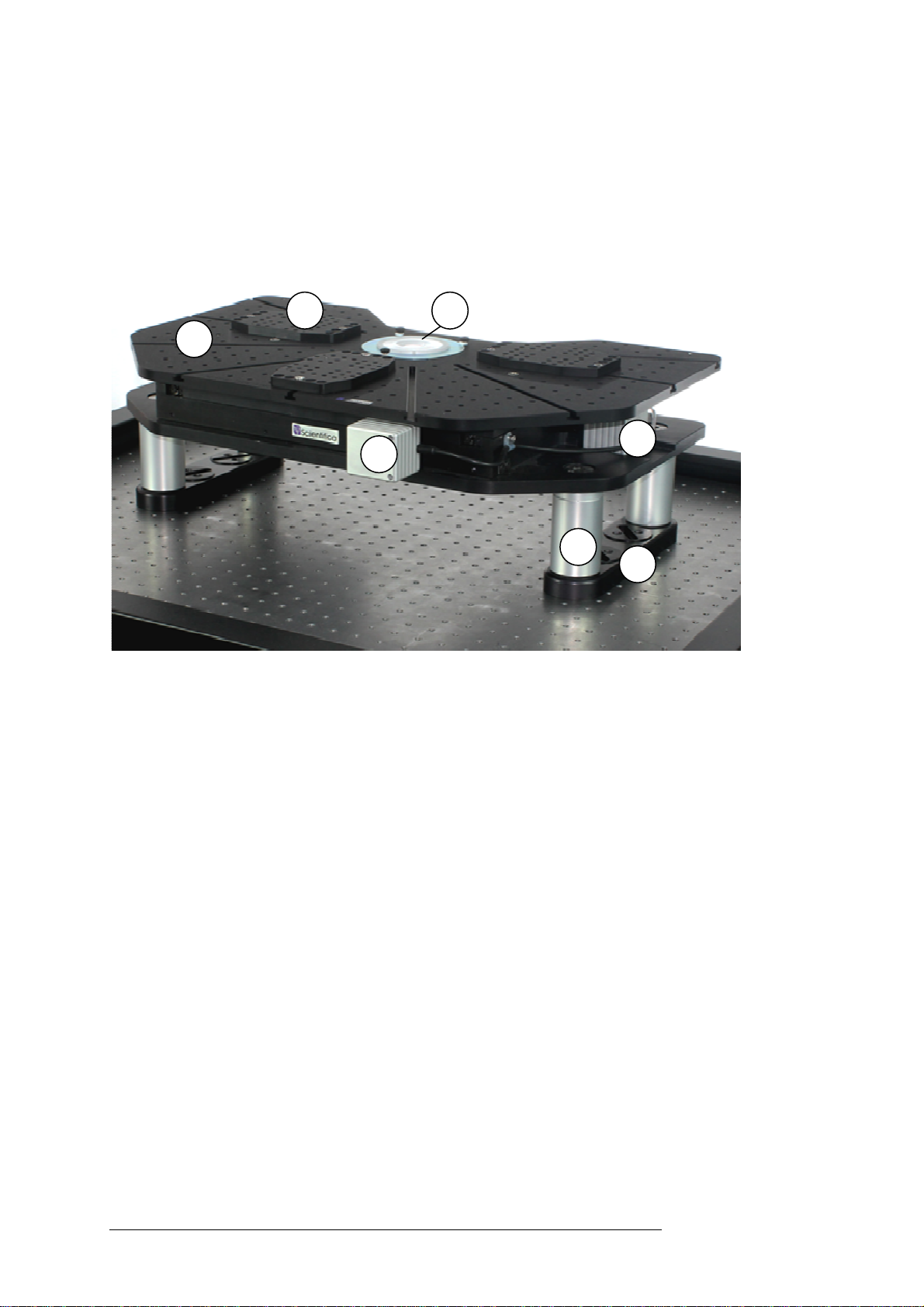
1.2.1 Product overview ..................................................................1
1.2.2 Product walkthrough .............................................................2
2.0 Packing List ...................................................................................3
3.0 Setup .............................................................................................4
3.1 Building the MMTP ......................................................................4
3.1.1 Removing shipping brackets.................................................4
3.1.2. Setting the correct length of your platform leg......................5
3.1.3. Attaching the legs and feet...................................................5
3.1.4 Positioning the Platform........................................................5
3.1.5 Bolting the platform to your table top.....................................6
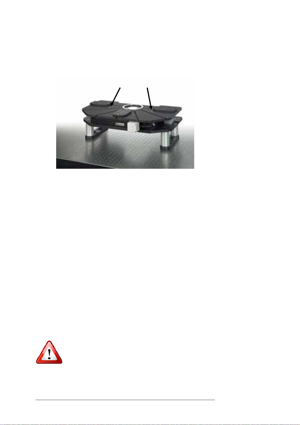
3.1.6 Using the Sliding Carriages...................................................6
3.2 Electrical setup of the MMTP.......................................................8
3.2.1 Control Racks .......................................................................8
3.2.2 Basic MMTP electrical setup diagram...................................9
3.2.3 Example system diagram....................................................10
4.0 Operation Guide ..........................................................................11
4.1 Powering up the system.............................................................11
4.2 Operating the MMTP..................................................................11
4.2.1 Using a Control Cube..........................................................11
4.2.2 Using a PatchPad...............................................................13
4.2.3 Using a Joystick..................................................................15
5.0 Maintenance................................................................................. 16
5.1 Cleaning ....................................................................................16
6.0 Frequently Asked Questions ......................................................17
6.1 No Movement............................................................................17
6.2 Drift............................................................................................17
7.0 Specifications..............................................................................19
7.1 Top plate schematics.................................................................19
8.0 LinLab ..........................................................................................20
8.1 Installing the software................................................................20
8.1.1 Connecting the system........................................................20
8.1.2 Installing the USB Drivers ...................................................21
8.1.3 USB port assignment..........................................................23
8.2 Running the software.................................................................24
8.2.1 Zero Current Position..........................................................25
8.2.2 Step Control........................................................................25
8.2.3 Virtual Joystick....................................................................25
8.2.4 Home Out, Home In and Step In.........................................26
8.3 LinLab Menus............................................................................26
8.3.1 Configure / Communications Port........................................26
8.3.2 Configure / System Configuration........................................27
8.3.3 Manipulator / Set Home Out Position..................................28
8.3.4 Manipulator / Set Home In Offset........................................28
8.3.5 Manipulator / Step Size After Home In ................................29

2| 1.0 Product Introduction
8.3.6 Manipulator / Reverse X (Y or Z) Direction Units.................29
8.3.7 Manipulator / Reverse X (Y or Z) Rotary Motion..................30
8.3.8 Manipulators/ Follow Control...............................................30
8.3.9 Manipulators/ Creeper.........................................................31
8.3.10 Manipulators/ PPL Wheel ReMap......................................31
8.3.11 View ..................................................................................31
8.3.12 View / Show Stored Points ................................................32
8.3.13 Approach...........................................................................34
8.3.14 Speed................................................................................34
8.3.15 The Joystick / Rotary Speed scaling..................................34
8.3.16 Acceleration / Deceleration................................................34
8.3.17 Z Speed Scaling................................................................35
8.4 Programming linear motion and Heater Cards............................35
9.0 Warranty, Technical Queries and Returns .................................39
10.0 About Scientifica........................................................................40

1.0 Product Introduction |1
1.0 Product Introduction
1.1 Handling Scientifica equipment – precautions
This section contains important safety information related to general use
of the MMTP. The Scientifica MMTP is a piece of scientific equipment
and as such requires care when handling.
• Before use, carefully read the instructions, including all warnings and
cautions.
• Inspect the product, any cables, and connectors before each use. Do
not use any equipment that appears damaged.
• Do not apply excessive tension to any cable.
• There are no user serviceable parts inside the unit.
• Always disconnect the instrument from the power supply prior to
cleaning the system or performing maintenance work.
Other important safety information appears throughout the manual.
Adjustment or removal of any screws or components
other than those noted in this manual can adversely
affect the performance and operation of your
micromanipulator and may invalidate your warranty.
1.2 The Scientifica MMTP
1.2.1 Product overview
Compatible with all major upright microscopes the MMTP (Motorised
Movable Top Plate) is ideal for use with a confocal or multiphoton
system. The MMTP offers 25 mm of super smooth X & Y travel with a
resolution of 20 nm. The manipulators and sample can be positioned as
one, allowing movement to different fields of view of the objective, whilst
the microscope remains fixed. This means that you can image different
areas of interest whilst maintaining delicate patch clamp experiments.
Up to 50 memory positions can be stored and recalled in X,Y & Z (focus)
axes. The ultra-low noise electronics means you can continue to record
sensitive signals even during sample adjustment. Platform positioning
can be carried out by either a PatchPad, Joystick, Control Cube or with
a PC.

2|
1.2.2 Product walkthrough
1 - Top plate
2 - Sliding carriage mounting plate
3 - Sample chamber
4 - X Y Motors (attached to the translation stage)
5 - Adjustable legs
6 - Feet
1
2
5
6
4
4
3

2.0 Packing List |3
2.0 Packing List |3
2.0 Packing List
If the outside of the shipping packaging is damaged, notify your shipping
department immediately. The shipping department may wish to notify
the carrier at this point.
If the shipping carton is not damaged, carefully remove and identify all of
the components as listed below. If any of items are missing, contact
Scientifica Ltd. Please retain the packaging for storage or future
transportation of the system.
• Sample plate
• Locking ring
• Break out box
• 25 Way to 25 Way lead
• USB Cable
• Digital Vernier Caliper
• 1 x Screw Kit
• Hex Key set
• 10 mm Allen Key
• (Optional) Z-focus module
• LinLab CD (section 8.0)
Top Plate
3 x Manipulator mounting
plates
Motorised XY Translation
stage
8x Leg bolts
(usually shipped
screwed into legs)
4 x Adjustable legs
2 x Feet
4 x Foot Mounting
Locks
1U Control Rack

4|
3.0 Setup
3.1 Building the MMTP
To get the best performance out of your platform it must be set up
precisely.
Please follow the steps in this manual to ensure the platform is set up in
accordance with manufacturers’ guidelines.
Please remember: adjustment or removal of any screws
or components other than those noted in this manual
can adversely affect the performance and operation of
your equipment and may invalidate your warranty.
3.1.1 Removing shipping brackets
Special shipping brackets are added to your MMTP to prevent damage
during shipment. These are bright red and found on the inside arms of
the XY translation stage.
Remove the shipping brackets using the Hex Key provided.
Note: retain the brackets for future use.
Figure A: Removing shipping brackets

3.0 Setup |5
3.0 Setup |5
3.1.2. Setting the correct length of your platform leg
It is essential that you ensure the legs are all the
same height. Any differences in leg length will reduce
the smoothness of the stage motion and damage the
bearings.
It is important to ensure that the platform height is set to correct focal
point of your microscope. For a Scientifica SliceScope the height is 219
mm. (This information should be supplied by your microscope
manufacturer – Olympus, Zeiss, Leica, Nikon).
Figure B: Setting the platform height
Minimum platform height is 190 mm. Once you have decided on the
correct height, unscrew the legs to the desired length. Use the digital
callipers to ensure that all of the MMTP legs are the same length.
Tighten the locking ring to ensure that the height does not change.
3.1.3. Attaching the legs and feet
Bolt the feet to the legs using the supplied leg bolts with the 10 mm allen
key. Align the legs with the XY stage and bolt firmly together with the 10
mm allen key.
Measure this
height
Locking Ring

6| 3.0 Setup
3.1.4 Positioning the platform
Ensure the microscope optics are out of the way before positioning to
avoid damage. Put the platform in position near your microscope and
carefully slide the top plate into position. Lock the top plate in place by
gently tightening the bolts with the Hex key supplied.
Figure C: Locking the top plate in position
Ensure that the central hole of the sample plate is aligned with your
microscope objective.
3.1.5 Bolting the platform to your table top
Once the platform is in the correct position, place the four foot mounting
locks into the feet.
By rotating the mounting locks, you will expose a tapped hole in the
table. Using the bolts supplied, bolt the feet firmly to your table surface.
This will be either M6 for metric tables or ¼ 20 for inch spaced tables.
3.1.6 Using the sliding carriages
As an alternative to mounting devices directly on the tapped surface of
the top plate, three carriages are supplied for when finer positioning
control is required.
These are usually used for mounting and repeatable positioning of
micromanipulators, which can be attached directly to the carriage using
the bolts supplied.
Ensure that the bolts used to mount devices do not
extend beyond the lower surface of the carriage to
prevent damage to the top plate surface.
The T-bar can be mounted to the lower surface of the carriage in any of
the five hole positions for additional lateral positioning versatility.

3.0 Setup |7
3.0 Setup |7
Figure D: Mounting carriages.
The right-hand carriage is inverted to reveal a T-bar
mounted in the central lateral position.
To fit the mounting carriages to the top plate, loosen but do not remove
the bolts holding the T-bar in place using the supplied hex key. Slide the
carriage onto the top plate from the outer edge.
When in position, retighten the T-bar bolts to secure the carriage in
place. It is important to complete this step to ensure complete stability.

8| 3.0 Setup
3.2 Electrical setup of the MMTP
To operate, the MMTP will require connecting to a control rack and user
interface. There is also an optional connection via USB for PC control
using LinLab software.
3.2.1 Control racks
The control rack will be factory configured with either one or two control
cards. One card is required for each device attached, with a maximum
of two being controlled by each control rack. If the MMTP is being used
with another Scientifica motorised device, it may have been configured
to operate both devices from one rack. When a rack is configured with
two control cards it can either be connected with one user interface
switchable between either card or two user interfaces, one for each
card.
Note: Control racks are pre-configured for use with the supplied
device and controller. Changing the connected devices will
require reconfiguration of the control rack. If you need to alter
your setup, please contact Scientifica.
The MMTP is connected to the control rack by a 25 way cable and
breakout box. The user interface connects by a 15 way to D-type to
RJ45 cable
TTL
25wayD-type
connector for
first motion
card
15wayD-type
connectorfor
first user
interface
ACMainsInput
and Fuse
25wayD-type
connectorfor
second
motion card
TTL in/out
(optional)
15wayD-type
connectorfor
second user
interface
USBconnection
foroptional PC
interface
Figure A: Rear panel of the 1U Rack mounted controller
Note: Optional TTL input/output. When fitted, the option is
factory configured to accept either a 5V input or output signal as
follows.
TTL In – Inputting a 5V pulse will cause the MMTP to move in the same
way as pressing the MR key on the control cube.
TTL Out – Pressing the MR key on the control cube will output a 5V
pulse.

3.0 Setup |9
3.0 Setup |9
3.2.2 Basic MMTP electrical setup diagram
Caution: Never connect or disconnect any cables with the
1U Control rack switched on.
Figure B: Basic electrical connections schematic

10| 3.0 Setup
3.2.3 Example system diagram
The MMTP can be incorporated into Scientifica’s modular electrical
system, enabling control consoles to be shared between devices.
Figure C: Example system connection schematic

4.0 Operation Guide |11
4.0 Operation Guide
4.1 Powering up the system
Once all positioning and cable connections are complete you are ready
to switch on your system.
Power on the system using the switch on the front of the 1U rack
controllers. The purple Scientifica logos will illuminate, indicating the
system is powered up.
4.2 Operating the MMTP
Movement of the MMTP is achieved using the user interface supplied.
Functionality of each user interface type is described as follows:
4.2.1 Using a Control Cube
Figure D: Control Cube user interface
Device selection – Located on the side of the cube. Selects which
device to control when two devices and one user interface are
connected to a controller rack. Where only one device is connected,
position II will disable the connected device, preventing unintentional
movement.
Blue wheel – Moves the MMTP left and right (X axis).

12| 4.0 Operation Guide
Green wheel – Moves the MMTP front and back (Y axis).
Red wheel – Redundant when controlling the MMTP (unless z-module
is attached)
Speed +/- – Sets responsiveness to control wheel movement. Fast for
rapid positioning. Slow for fine movement.
Approach 0/1 – Redundant when controlling the MMTP
Step – Pressing the Step button causes the MMTP to move a set
distance. The factory default setting for the step size is 0.01 mm. This
value can be changed using LinLab control software.
M+ - Pressing the M+ button stores the current position of the MMTP in
memory. Moving the MMTP and pressing M+ again will store another
position. Up to 50 memory positions can be stored.
MR - Pressing the MR button will recall the first stored memory position.
If more than one position is stored subsequent presses of the MR button
will recall each position stored in the same sequence they were saved.
Note: To clear stored memory positions, simultaneously press
the M+ and the MR buttons. This will remove all stored positions
from memory.
H in & H out – These buttons allow two positions to be stored in
memory, the Home In position and the Home Out position. The Home
Out position must be set first before Home In can be used.
To set Home Out move the MMTP to the desired position then press H
out for 3 seconds to store the current position. Subsequent pressing of
Home Out will cause the MMTP to move out to the stored Home Out
position until an alternative Home Out position is stored.
The Home In position can be set in two modes:
Mode 1 – This is the default mode. The Home In position can only be
set once a Home Out position is set. From the Home Out
position, pressing the Home In button will cause the MMTP to return its
original position prior to Home Out, minus a safety offset. This value can
be configured using the LinLab control software.
Mode 2 - This allows the user to set a specific position as the Home In
point. Move the MMTP to the desired Home In position then hold down
the Home In button for 3 seconds. The current position is stored to
memory as the Home In position. No Home in offsets will be applied in
Mode 2.
Note: If the Home Out and Home In buttons are held down
simultaneously, the Home Out and Home In positions will be
cleared and the Home In will be set back to Mode 1.

4.0 Operation Guide |13
4.2.2 Using a PatchPad
Figure E: PatchPad control device
Left wheel (X)– Moves the left and right X axis (blue). The push buttons
above the wheel to the left and right will move the MMTP in fast mode
when pressed.
Middle wheel (Y) – Moves the front and back Y axis. The push buttons
above the wheel to the left and right will move the MMTP in fast mode
when pressed.
Right wheel (Z)– Redundant when controlling the MMTP (unless a Z-
focus module is being used)
Note: Wheels can be remapped in LinLab to control a different
axis if required. Review the LinLab operation manual for more
information.
Device selection switch I/II – Selects which device to control when
two devices and one user interface are connected to a controller rack.
Where only one device is connected, position II will disable the
connected device, preventing unintentional movement.
Approach 0/1 – Redundant when controlling the MMTP
Speed +/- – Sets responsiveness to control wheel movement. Fast for
rapid positioning. Slow for fine movement.
Step – Pressing the Step button causes the MMTP to move a set
distance. The factory default setting for the step size is 0.01 mm. This
value can be changed using LinLab control software.

14| 4.0 Operation Guide
M+ - Pressing the M+ button stores the current position of the MMTP in
memory. Moving the MMTP and pressing M+ again will store another
position. Up to 25 memory positions can be stored.
MR - Pressing the MR button will recall the first stored memory position.
If more than one position is stored subsequent presses of the MR button
will recall each position stored in the same sequence they were saved.
Note: To clear stored memory positions, simultaneously press
the M+ and the MR buttons. This will remove all stored positions
from memory.
H in & H out – These buttons allow two positions to be stored in
memory, the Home In position and the Home Out position. The Home
Out position must be set first before Home In can be used.
To set Home Out move the MMTP to the desired position then press H
out for 3 seconds to store the current position. Subsequent pressing of
Home Out will cause the MMTP to move out to the stored Home Out
position until an alternative Home Out position is stored.
The Home In position can be set in two modes:
Mode 1 – This is the default mode. The Home In position can only be
set once a Home Out position is set. From the Home Out
position, pressing the Home In button will cause the MMTP to return its
original position prior to Home Out, minus a safety minus a safety offset.
This value can be configured using the LinLab control software.
Mode 2 - This allows the user to set a specific position as the Home In
point. Move the MMTP to the desired Home In position then hold down
the Home In button for 3 seconds. The current position is stored to
memory as the Home In position. No Home in offsets will be applied in
Mode 2.
Note: If the Home Out and Home In buttons are held down
simultaneously, the Home Out and Home In positions will be
cleared and the Home In will be set back to Mode 1.

4.0 Operation Guide |15
4.2.3 Using a Joystick
Figure F: Joystick control device
Move the joystick in the direction of travel required.
Moving the joystick to the left or right will move the MMTP left or right in
the axis.
Moving the joystick to the front or back will move the MMTP forwards or
backwards in the Y axis.
Note: Speed varies according to the amount of deflection
applied to the joystick.
Turbo – Pressing the button on the top of the joystick enables high
speed movement. When released movement will revert to fine control.
Memory – Pressing the Memory button will store the current position of
the MMTP to memory. Moving the MMTP and pressing Memory again
will store another position.
Step – Pressing the Step button will move the MMTP to the first stored
position in memory. If more than one position is stored subsequent
presses of the MR button will recall each position stored in the same
sequence they were saved.
Home In & home out –
These buttons allow two positions to be stored in memory, the Home In
position and the Home Out position. The Home Out position must be
set first before Home In can be used.

16| 5.0 Maintenance
5.0 Maintenance
WARNING: Do not tamper with any fixings other than
those indicated in the manual for mounting purposes.
There are no user serviceable parts within the MMTP.
5.1 Cleaning
WARNING: Switch off and disconnect the mains supply
before cleaning the unit.
Use a soft cloth dampened with water or a mild detergent to wipe over
the unit.
•Do not saturate the unit.
•Never allow fluid to enter the unit.
•Do not use any type of abrasive pad or material to clean the unit.
Table of contents
Other Scientifica Laboratory Equipment manuals

Scientifica
Scientifica SliceMate User manual

Scientifica
Scientifica MMBP Manual instruction

Scientifica
Scientifica UMS Manual instruction

Scientifica
Scientifica IVM Manual instruction

Scientifica
Scientifica MTP Guide

Scientifica
Scientifica MDU Manual instruction

Scientifica
Scientifica LBM-7 User manual

Scientifica
Scientifica Multiphoton Scanhead Manual instruction