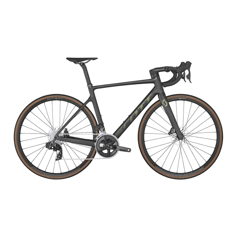
Scott Foil Di2 User manual


2 3
THE NEW FOIL FEATURES THE SAME LIGHTWEIGHT FRAME CHARACTERISTICS AS ITS PREDECESSOR AND IS AMONGST THE LIGHT-
EST AERO BIKES ON THE MARKET. THE FRAME AERODYNAMICS OF THE BIKE HAVE BEEN REWORKED FROM THE HEADTUBE ALL
THE WAY TO THE REAR DROPOUTS, STIFFNESS AND COMFORT VALUES HAVE BEEN LIFTED TO A NEW LEVEL AND THE INTEGRATED
COCKPIT IS JUST ONE EXAMPLE THAT SHOWS HOW FAR COMPONENT INTEGRATION HAS BEEN TAKEN ON THE NEW FOIL. THE IDEA
BEHIND THIS MANUAL IS TO GUIDE YOU THROUGH THE BUILD-UP OF A DI2-EQUIPPED FOIL. LARS TEUTENBERG, TECHNICAL TEAM
LIASON, KNOWS ALL THE LITTLE TRICKS TO ENSURE THAT THE BUILD OF THE NEW FOIL CAN BE DONE QUICKLY AND EFFICIENTLY.

4 5
FRONT BRAKE
REAR BRAKE
FD
FD
500-650
1200
650
250
mm
A
B
CD
mm
mm
mm
A B C D
ELECTRONIC SHIFTING CONFIGUARTION :
SM-EW90-A
CPU
JUNCTION
SM-JC41
BATTERY SM-BTR2
FRONT BRAKE
FD
RD
REAR BRAKE
35
mm
35
mm
1200
mm
Before you start assembling the bike, we recommend doing an inventory check of all parts (components, cables, wires, junctions,
etc.), as well as a brief function test of the electronic Shimano Di2 groupset. To do so, connect all Shimano parts and connect via
SM-PCE1 or SM-BCR2 to a laptop. Update all components with the e-tube software.
Finally, check whether the drivetrain functions properly.
GETTING STARTED
Wiring diagram: before you start building the Foil, check out the wiring diagram in order to use the right parts in the right places.
Follow Shimano’s instructions regarding the installation of Di2 parts.

6 7
FOIL BUILD UP MANUAL / SCOTT / FOIL / 2016
Start the build-up of the Foil with the integrated Syncros Aero RR1.0 Cockpit. It’s considerably easier to install the cables on the
cockpit when it’s not mounted on the fork. The Syncros Aero RR1.0 Cockpit is available in 9 dierent stem length/bar width com-
binations as an aftermarket piece. Thanks to a reducer shim, the cockpit is compatible with both 1 1/4” and 1 1/8” steerers.
Start the bar assembly with the two 35mm connecting wires for the shifters. Turn the bar upside down and insert the cables into
the distant holes on the left and right side respectively. Push the cables to the center and pull them out where the junction box is
ultimately going to be placed. A tool or a simple spoke might help to get the cables out. Make sure the cable between the shifter
and the cable entry on the bar is loose in order to avoid over-tensioning once bar tape is applied. Over-tensioning often causes
malfunction because the wire can be unplugged.
Insert a 1200mm Di2 cable into the right brake cable exit (top view) and
push it towards the center. Pull it out through the big opening. For English
brake setups use the left hole instead.
This cable will later connect the junction box (Junction A) with the inter-
nal junction box (Junction B).

8 9
FOIL BUILD UP MANUAL / SCOTT / FOIL / 2016
Insert the brake cable into the distal hole and pull it out of the medial brake
cable hole (don’t cross over the big center opening for the junction box).
Here again, a spoke might help to pull the cable out of the medial hole.
Connect all three cables to the 3 port junction
box (Junction A/SM-EW-90-A). Use a Shimano
tool to ensure a firm connection.
Mount the brake leavers on the bar. Check that the brake cables are correctly pre-installed. Repeat the same procedure on the other side.

10 11
We recommend using a Shimano Direct Mount Quick Release (SM-CB90)
which facilitates rear brake adjustment on the Foil. Install the QR either
5cm from the bar or in the middle of the externally routed brake cable
under the bottom bracket.
To correctly install the cable housings, start by cutting them to the right length. Slide the housings over the pre-installed brake
cables. Use a bit of oil or grease to reduce the friction. Make sure that the cable housing sits tightly in the foreseen opening of the
brake leaver.
FOIL BUILD UP MANUAL / SCOTT / FOIL / 2016
Fix the junction box (Junction A) to the cover by
using a zip tie.
Make sure the button of the junction box is
placed correctly under the hole of the cover.

12 13
Slide the installed junction box into the opening of
the cockpit from the front at a 45° angle. Make sure
the button is still placed under the hole of the cover.
Align the cover correctly and fix it with the two bolts. Tighten the bolts to
1-1.5Nm using an Allen key.
FOIL BUILD UP MANUAL / SCOTT / FOIL / 2016
If you want to equip the Foil with Shimano’s Di2 Sprint Shifters
(SW-R610), install them right under the brake levers and connect
the Sprint Shifter wire with the brake lever using the Shimano tool.
Before the rear brake cable is inserted into the frame, make sure
you pre-install cable guides or a shrinking tube in order to hold
together the cable housing and the Di2 wire.

1514
Use the correct cable guide for the downtube. There is one specifically for Di2 mounts
and one for mechanical groupsets. Before inserting the cables into the frame, make
sure to guide the cables through the indicated openings of the cable guide.
Start mounting the frameset by placing the bigger 1 1/4“ bearing on the fork crown
and the smaller 1 1/8” on the top using assembly grease. Add the compression ring
on top of upper bearing.
FOIL BUILD UP MANUAL / SCOTT / FOIL / 2016
Continue with the headset cover and the required
amount of spacers. SCOTT oers specific aero-spac-
ers for the Foil available in the following sizes: 2mm,
5mm, 10mm and 20mm. The Foil is delivered with
1x20mm, 2x10mm, 1x5mm and 3x2mm spacers.
Mount the pre-installed Syncros
cockpit on the steerer.

16 17
Mark the top end of the stem on the steerer and cut
the steerer 3-4mm below the marking. If you are
unsure about your final bar height, include some
standard 1 1/4” round spacers on top of the stem to
maintain flexibility for height adjustment.
Install the headset expander by sliding it into the steerer under slight tension.
FOIL BUILD UP MANUAL / SCOTT / FOIL / 2016
Tighten the expander to 8-10Nm. Use a torque wrench to ensure that you don’t overtighten the bolt.

1918
Install the cockpit and loosely tighten the screw of the top cap.
Insert the rear cap and position it correctly by lifting the stem about 1-2mm. Continue by tightening the top cap screw until the
head set play is balanced. Finish the handlebar mount by tightening the stem to a maximum of 5Nm. Use a torque wrench to
ensure that you don’t overtighten the stem bolts.
FOIL BUILD UP MANUAL / SCOTT / FOIL / 2016
Fix the Di2 wire that goes into the frame to
the rear brake cable with a piece of tape.
This will facilitate pushing both cables
through the frame. Make sure the shrinking
tube and cable guide have been installed
according to the above description before
you proceed with this step.
Insert the cables into the opening on top of the downtube
and push them down until they appear at the bottom bracket
opening of the frame.

20 21
Remove the tape and install the internal junction
(SM-JC41/Junction B) to the Di2 wire.
Insert a 650mm Di2 wire into the opening of the dropout and
push it towards the bottom bracket opening. Plug the cable
into the internal junction box (Junction B).
FOIL BUILD UP MANUAL / SCOTT / FOIL / 2016
Mount the rear derailleur, install a rubber seal
on the Di2 wire and connect the latter to the
rear derailleur using the recommended tool
from Shimano.
Insert a 250mm Di2 wire into the hole below
the front derailleur mount and connect it with
the internal junction box (Junction B).

2322
Install the front derailleur with the Foil-specific
carbon plate. This replaces the original piece that
comes standard with Shimano front derailleurs. The
derailleur hanger will be damaged if the original
Shimano pieces are used.
After the front derailleur has been mounted, adjust
the frame stopper bolt so that it sits tightly on the
frame. Without proper adjustment of the stopper
bolt, it is possible that the front derailleur hanger
can be damaged during the shifting process. A
properly adjusted stopper bolt will also improve
shifting performance.
FOIL BUILD UP MANUAL / SCOTT / FOIL / 2016
Fit a rubber seal over the Di2 wire and push it firmly into the
hole to finish the front derailleur installation.
To fix the internal Di2 battery on the bot-
tom of the seatpost, place the rubber
seals over the battery with the correct
side facing down.

2524
Align the rubber pieces correctly and push the battery into the
seatpost with the wire facing down.
Push a brake cable from the bottom bracket
through the seattube. Fix a 550mm Di2 wire with a
tape on the brake cable and pull it down the seat-
tube and out of the bottom bracket box.
FOIL BUILD UP MANUAL / SCOTT / FOIL / 2016
Connect the Di2 wire with the internal junction box
(Junction B).
To install the internal seatpost clamp, start by putting grease on the tightening bolt. Make sure no grease reaches the concave
contact area of the post.

2726
Place the seatclamp with the front section (as indicated) facing the direction of the toptube into the opening of the frame. Make
sure the red front and back pieces remain properly aligned (left side). If this is not the case (right side), the bolt needs to be over-
tightened in order for the seatpost to stay in place.
FOIL BUILD UP MANUAL / SCOTT / FOIL / 2016
It is easier to mount the saddle on the seatpost when the
seatpost is not yet fixed in the frame. Make sure to use the
correct fixation clamp. There are versions for round and oval
shaped rails available.
Connect the Di2 wire that is routed through the seatpost with the internal Di2 battery mounted on the seatpost. Use carbon
grease on the seatpost to increase friction. Slide the seatpost into the frame carefully so as to not damage the Di2 wire. Pull the
cable slightly from the bottom. Tighten the bolt of the seatclamp to 5Nm Use a torque wrench to avoid overtightening of the bolt.

2928
Mount the Shimano Direct Mount rear brake. Pull the brake cable out of the hole on the downside of the downtube. Here again, a
spoke might help to get the cable out of the frame.
Push the internal junction box slightly into the downtube. Place the Shimano
press fit bottom bracket in such a way that the cables are not squeezed. Press
the bottom bracket into the frame using the correct Shimano tool. Place the
rubber piece into the hole under the bottom bracket.
FOIL BUILD UP MANUAL / SCOTT / FOIL / 2016
Place the cable stop and measure the
housing to the correct length. Make sure
the cable can always move freely when full
brake force is applied.
Fix the brake cable on the Shimano Direct Mount rear brake.

3130
Adjust the brake housing to the correct length so that
steering remains unrestricted.
Install the front brake on the fork.
FOIL BUILD UP MANUAL / SCOTT / FOIL / 2016
To install the crankset, push the axle through the bottom bracket. Tighten the cover screw
with the respective Shimano tool and make sure it doesn’t sit too tightly. Tighten the bolts
on the left crank arm to 13-15Nm. Use a torque wrench to avoid overtightening of the bolts.
Shorten the chain to the correct length and mount it by using a chain
tool for Shimano. Make sure the orientation of the chain is correct.

3332
Install the front and rear wheel and make
sure they are properly aligned with the
frame. Align the brake pads to the rim and
adjust the distance. Make sure you use the
recommended brake pads for your wheelset.
Wrap the handle bar tape and fix it with tape right after the radius where
the bar features a small step. The top of the bar is ergonomically shaped
and features an anti-slip coating so that no bar tape is required.
FOIL BUILD UP MANUAL / SCOTT / FOIL / 2016

34 35
W I N
EVERY
RIDE
FOIL BUILD UP MANUAL / SCOTT / FOIL / 2016

36
FOIL
BUILD UP
MANUAL
SCOTT | 2016
SCOTT-SPORTS.COM
Table of contents
Other Scott Bicycle manuals

Scott
Scott FOIL RC 47 XXS User manual

Scott
Scott Bicycle User manual

Scott
Scott Genius LT 2016 User manual

Scott
Scott genius mc 2007 User manual

Scott
Scott VOLTAGE FREERIDE User manual

Scott
Scott Genius 2015 User manual

Scott
Scott Addict Disc User manual

Scott
Scott BIG ED 2016 User manual

Scott
Scott S / 900 User manual

Scott
Scott Solace Disc User manual

Scott
Scott SOLACE 2023 User manual

Scott
Scott SPARK MY22 User manual

Scott
Scott SPARK User manual

Scott
Scott Voltage FR 700 User manual

Scott
Scott GENIUS 920 Configuration guide

Scott
Scott Addict Disc User manual

Scott
Scott SCALE CARBON User manual

Scott
Scott SPARK MY2017 User manual

Scott
Scott GAMBLER - 2011 User manual

Scott
Scott Gambler User manual