ENGLISH
09
…
DEUTSCH
FRANÇAIS
OWNER’S MANUAL 2007
08
In case you want more exact numbers of the shock air
pressure than shown on the decal on the frame or you’re
looking for tuning hints including different shock
characteristics of the Equalizer TC Shock, please have
a look at
www.scott-sports.com
In addition you can download this tuning program on
your pc.
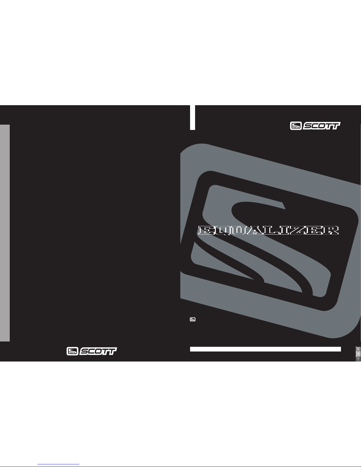
MORE DETAILS ABOUT
EQUALIZER TC SHOCK SET-UP
MAINTENANCE / SERVICE
GUIDE
Please clean regularly after riding off-road the
shock piston and all other parts in motion of the
shock with a soft and wet cloth or if needed with
mild soap to prevent from excessive wear and tear.
For maintenance and service please refer to the
following table:
Maintenance period
Check of air pressure
Check of rebound
Clean shock bushings,
check for tear and wear,
grease
Change of oil/inspection
at Scott Shock Service
Clean shock housing
Clean Lockout mechanism
New Every ride Every 8
hours
Every 40
hours
Every 1000
hours / min.
1 x year
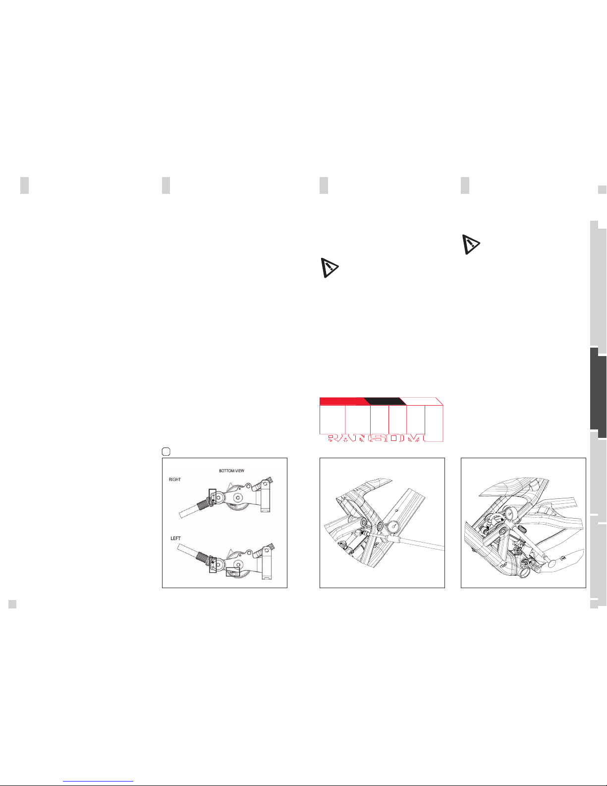
The negative travel is important when crossing grooves
or holes on the trail.
If the bike is well adjusted the rear wheel and the swing-
arm will roll through the groove without the mainframe
moving.
The SAG should be 15-20% of the travel for race orien-
ted riders and 20-25% of the travel for comfort oriented
riders.
The SAG-Boy indicates the recommended eye-to-eye
distance of the shock bolts of the Ransom models.
To check the adjustment, please follow as shown below:
1. sit on the bike, put your feet on the pedal
2. ask a second person, to put the color beam of the
SAG-Boy, recommended for your bike model, aside the
eye-to-eye distance of the shock bolts. - if the distance
between the bolts is corresponding to the length of the
color beam, the air pressure is matching to your weight
- if the distance between the bolts is longer than the
length of the color beam, the air pressure of the positi-
ve chamber is too high and should be carefully reduced
by using the bleed knob of the shock pump until the
measures are corresponding
- if the distance between the bolts is shorter than the
length of the color beam, the air pressure of the positive
chamber is too low and should be increased by using
the shock pump until the measures are the same.
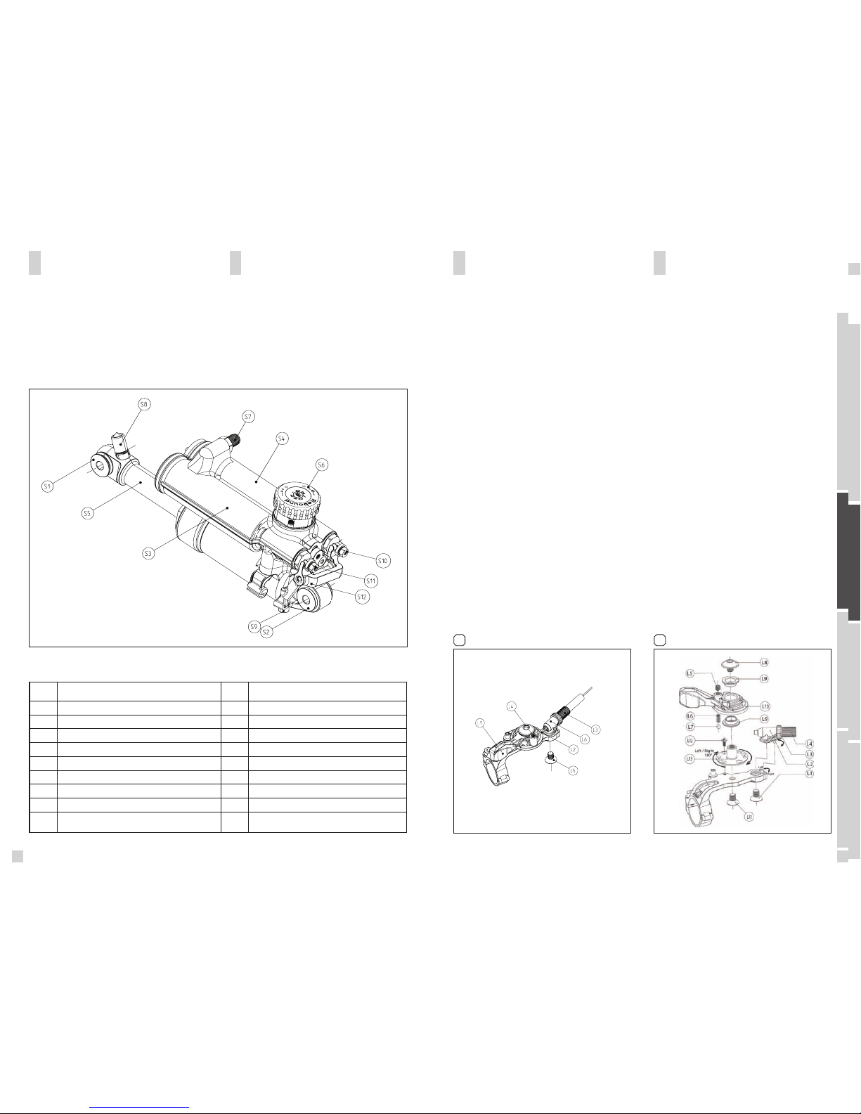
SET-UP OF REBOUND
EQUALIZER TC SHOCK
“Rebound” describes the speed the shock comes
back to its original length after absorbing an obstacle.
By using the red rebound screw (S6) you can adjust
the rebound step by step.
Please refer to the following instruction:
Ride your bike off a pavement (remain in the saddle)
and check how many times it bounces.
- if it bounces 1-2 times, the set up is good.
- If it bounces more than 3 times the rebound is too
fast. Turn the screw 1-2 “clicks” clockwise
- If it does not bounce the rebound is too slow. Turn
the screw 1-2 “clicks” counter clockwise.