manuals.online logo
Brands
  1. Home
  2. •
  3. Brands
  4. •
  5. SDMO
  6. •
  7. Inverter
  8. •
  9. SDMO PRO 3000 E Instructions for use

SDMO PRO 3000 E Instructions for use

This manual suits for next models

1

Other SDMO Inverter manuals

SDMO 6500 TE Instructions for use

SDMO

SDMO 6500 TE Instructions for use

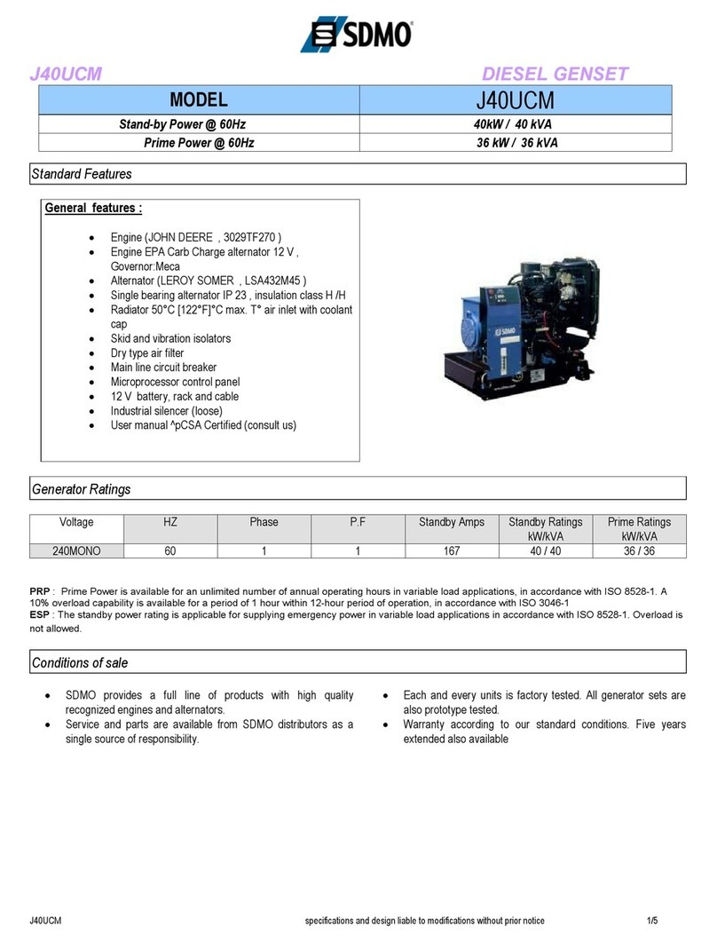
SDMO J40UCM User manual

SDMO

SDMO J40UCM User manual

SDMO AQUALINE TR 3.60 H Instructions for use

SDMO

SDMO AQUALINE TR 3.60 H Instructions for use

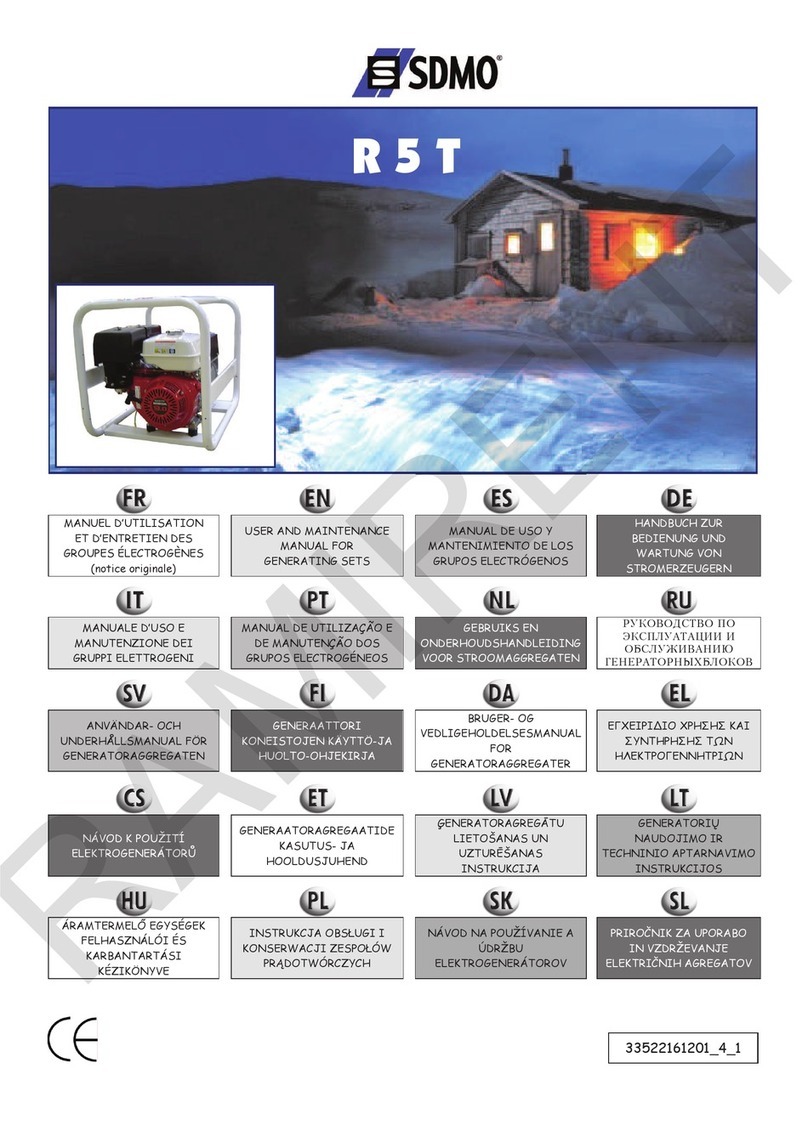
SDMO R5T Operating instructions

SDMO

SDMO R5T Operating instructions

SDMO PRO 2000 Instructions for use

SDMO

SDMO PRO 2000 Instructions for use

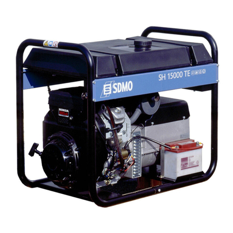
SDMO SH 10000E Operating instructions

SDMO

SDMO SH 10000E Operating instructions

SDMO TECHNIC 15000 TE Instructions for use

SDMO

SDMO TECHNIC 15000 TE Instructions for use

SDMO ALIZE 3000 Operating instructions

SDMO

SDMO ALIZE 3000 Operating instructions

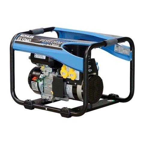
SDMO KOHLER PERFORM 3000 TB UK C5 Instructions for use

SDMO

SDMO KOHLER PERFORM 3000 TB UK C5 Instructions for use

SDMO R44C3 Operating instructions

SDMO

SDMO R44C3 Operating instructions

Popular Inverter manuals by other brands

Omnik New Energy Omniksol-1.5k-TL user manual

Omnik New Energy

Omnik New Energy Omniksol-1.5k-TL user manual

Agilent Technologies 33250A user guide

Agilent Technologies

Agilent Technologies 33250A user guide

4-noks ZR-SWITCH-RC instruction manual

4-noks

4-noks ZR-SWITCH-RC instruction manual

V&T V5 Series user manual

V&T

V&T V5 Series user manual

Hon Turing HT-T-S1000-12 introduction

Hon Turing

Hon Turing HT-T-S1000-12 introduction

Metabo E 140 SP Plus Original operating instructions

Metabo

Metabo E 140 SP Plus Original operating instructions

BARRON EXITRONIX Tucson Micro Series installation instructions

BARRON

BARRON EXITRONIX Tucson Micro Series installation instructions

Baumer HUBNER TDP 0,2 Series Mounting and operating instructions

Baumer

Baumer HUBNER TDP 0,2 Series Mounting and operating instructions

electroil ITTPD11W-RS-BC Operation and Maintenance Handbook

electroil

electroil ITTPD11W-RS-BC Operation and Maintenance Handbook

Silicon Solar TPS555-1230 instruction manual

Silicon Solar

Silicon Solar TPS555-1230 instruction manual

Mission Critical Xantrex Freedom SW-RVC owner's guide

Mission Critical

Mission Critical Xantrex Freedom SW-RVC owner's guide

HP 3312A Operating and service manual

HP

HP 3312A Operating and service manual

Hoymiles HM-500T user manual

Hoymiles

Hoymiles HM-500T user manual

Nitecore SPM10 user manual

Nitecore

Nitecore SPM10 user manual

AEG Protect PV installation manual

AEG

AEG Protect PV installation manual

On Board TruePower Plus 1200MS owner's manual

On Board

On Board TruePower Plus 1200MS owner's manual

Plugreen PGM-200P-230 Installation and operation manual

Plugreen

Plugreen PGM-200P-230 Installation and operation manual

Fourgroup Easy use and Programming Handbook

Fourgroup

Fourgroup Easy use and Programming Handbook

manuals.online logo
manuals.online logoBrands
  • About & Mission
  • Contact us
  • Privacy Policy
  • Terms and Conditions

Copyright 2025 Manuals.Online. All Rights Reserved.

33522196101_3_1
05/2021
Manuel d'utilisation et d’entretien
(Notice originale)
Instruction and maintenance manual
(Translation of the original note)
Manual de utilización y mantenimiento
(Traducción de la información original)
Benutzer- und Wartungshandbuch
(Übersetzung der Original-Anleitung)
Gebruiks- en onderhoudshandleiding
(Vertaling van de oorspronkelijke handleiding)
Vedligeholdelses- og brugsvejledning
(Oversættelse af den originale brugervejledning)
Instruksjoner og sikkerhetsregler
(Oversettelse av de originale instruksjonene)
Bruks- och underhållsanvisning
(Översättning av originalinstruktionerna)
Käyttö- ja huolto-opas
(Alkuperäisen käyttöohjeen käännös)
Kasutus-ja hooldusjuhend
(Originaaljuhendi tõlge)
Naudojimo ir priežiūros vadovas
(Versta iš originalo)
Lietošanas un apkopes rokasgrāmata
(Oriģinālās instrukcijas tulkojums)
ﺔﻧﺎﻴﺼﻟﺍﻭ ﻡﺍﺪﺨﺘﺳﻻﺍ ﻞﻴﻟﺩ
(ﻲﻠﺻﻷﺍ ﻞﻴﻟﺪﻟﺍ ﺔﻤﺟﺮﺗ)
INVERTER
PRO 3000 E
PrIndus C5
A
4
6
8
14
19
6
1
24
15
17
12
16
7
11
27
18
26
21
22
20
23
13
25
14
8
5
10
9
4
2
3
B
C
1
1
3
2
2
6
4
3
1
4
3
1
D
E
F
FRANCE :
0.806.800.107 (Prix appel)
X
2
1
4
2
3
2
5
1
4
3
6
447_EN.docx 2021-05-28
CONTENTS
Section 1. Preface
Section 2. Instructions and safety regulations (personal protection)
Section 3. Getting started with the generating set
Section 4. Using the generator set
Section 5. Generating set maintenance
Section 6. Transporting and storing the generating set
Section 7. Repairing minor faults
Section 8. Technical specifications
Section 9. Conditions of warranty
Section 1. Preface
IMPORTANT
Material damage
Before use, read this manual and the safety instructions provided alongside it thoroughly. Keep these
safe throughout the unit's service life and always adhere to the safety advice and the usage and
maintenance instructions contained therein.
The information contained in this manual is taken from technical data available at the time of print (the photos shown in this manual
are not legally binding). In line with our policy of continually improving the quality of our products, this information may be amended
without warning. On request, we can supply our original manuals in French via our website.
In this manual, dangers are represented by the following two symbols:
DANGER
[Appropriate pictogram(s)]
RISK TO THE HEALTH OF THOSE CONCERNED
DANGER OF DEATH (if appropriate)
Indicates an imminent danger which may result in death or serious injury. Failure to follow the
instruction shown may pose serious risks to the health and life of those concerned.
IMPORTANT
Material damage
[At-risk equipment]
Indicates an at-risk situation. Failure to follow the instructions provided may result in minor injuries to
those concerned or material damage.
Section 2. Instructions and safety regulations (personal protection)
The instructions and safety regulations must be read carefully and followed to avoid endangering personal health and safety. If
there is any doubt over the meaning of the instructions, please contact your nearest agent.
2.1 Meaning of the pictograms on the generating set
DANGER
DANGER:
risk of electrocution
GROUND
DANGER:
risk of burns
Before starting,
check the oil level.
1
2
3
DANGER:
1 - Refer to the documentation supplied with the unit.
2 - Emission of toxic exhaust gases. Do not use in a confined or
poorly ventilated area.
3 - Stop the unit before filling with fuel.
2.2 General guidelines
Never let other people use the unit without ensuring they have all of the necessary instructions beforehand. Never allow a child to
touch the unit, even when switched off, and do not operate the unit when animals are in the vicinity (fear, disturbance, etc.).
In all cases, respect the local regulations currently in place concerning the use of the units. Exhaust gases, fuel and oil, or coolant
(if used), are toxic products; take all necessary protective measures.
2.3 Guidelines for protecting the environment
Drain the engine oil into a designated container: never drain or discard engine oil onto the ground.
As far as possible, avoid sound reverberating through walls or buildings (the noise will be amplified).
If the unit is used in wooded, bushy or uncultivated areas and if the exhaust silencer is not fitted with a spark arrester, clear any
vegetation away from the area and take care that the sparks do not cause a fire. Once the unit is no longer being used (end of
product life), take it to a waste collection point.
15/178
447_EN.docx 2021-05-28
2.4 Risks relating to exhaust gases
DANGER
RISK OF POISONING
DANGER OF DEATH (if appropriate)
The carbon monoxide present in the exhaust gas may lead to death by inhalation if the concentration
levels in the atmosphere are too high.
Always use the unit in a well ventilated area where the gases cannot accumulate.
For safety reasons and for correct operation of the unit, correct ventilation is essential (risk of poisoning, engine overheating and
accidents involving, or damage to, the surrounding equipment and property). If it is necessary to operate it inside a building, the
exhaust gases must be evacuated outside and adequate ventilation must be provided so that any people or animals present are not
affected.
2.5 Risk of fire
DANGER
RISK OF FIRE
DANGER OF DEATH
Never operate the unit in areas containing flammable products (risk of sparks). Keep all flammable or
explosive materials (e.g. petrol, oil, cloth, etc.) out of the way when unit is running. Never cover the unit
with any type of material while it is in operation or just after it has been turned off: always wait until the
engine cools down (at least 30 minutes).
2.6 Risk of burns
IMPORTANT
Before any intervention, wait for the unit to cool down (at least 30 minutes).
When running and just after stopping, the oil, engine and the exhaust silencer are hot and may cause burns if contact is made.
2.7 Risk of electrocution
DANGER
RISK OF ELECTROCUTION
DANGER OF DEATH
Units supply electrical current while operating; comply with the applicable legislation as well as the
installation and usage recommendations given in this manual. If you are in any doubt regarding
installation, please contact your nearest agent.
Do not connect the unit directly to other power sources (such as the mains for example); fit a source
changeover panel.
Never touch stripped cables or disconnected connectors. Never handle a unit with wet hands or feet.
Never expose the equipment to liquid splashes or rainfall, and do not place it on wet ground.
2.7.1 Temporary or semi-temporary installation (work site, show, fairground, etc.)
A - If the unit is not equipped with an integrated differential protection device at delivery (standard version with insulated neutral on
the unit's earth terminal):
- Use a differential device calibrated to 30mA at the output of each of the unit's sockets (place each device at least 1 metre from
the unit, protecting it from weather conditions).
- If one or more mobile or portable devices are used occasionally, the unit does not need to be earthed.
B - If the unit is equipped with an integrated differential protection device at delivery (standard version with alternating neutral
connected to the unit's earth terminal - for use with TT or TN systems):
- Connect the unit to the earth: attach a 10 mm2 copper wire to the unit's earth terminal (A1) and to a galvanised steel earthing
rod set 1 metre into the ground.
2.7.2 Fixed installation or mains failure
When supplying a fixed installation (e.g. as backup for mains outages), the unit must be connected by a qualified electrician in
accordance with the regulations applicable at the installation site. The units are not designed to be connected directly to an
installation (risk of electrocution or damage to equipment).
A - If the unit is not equipped with an integrated differential protection device at delivery (standard version with insulated neutral on
the unit's earth terminal):
- Use a source inverter.
- The unit does not need to be earthed.
B - If the unit is equipped with an integrated differential protection device at delivery (standard version with alternating neutral
connected to the unit's earth terminal - for use with TT or TN systems):
- Use a source inverter.
-Connect the unit to the earth: attach a 10 mm2 copper wire to the unit's earth terminal (A1) and to a galvanised steel
earthing rod set 1 metre into the ground.
2.7.3 Mobile application
The units are intended to operate while stationary. They may not be installed on a vehicle or other mobile equipment unless a study
has been carried out analysing the unit's various installation and usage specifications. It is prohibited to use the unit whilst it is in
motion. If earthing is not possible, connect the unit's earth terminal (A1) to the vehicle earth.
16/178
447_EN.docx 2021-05-28
2.7.4 Connection and choice of cables
For all connections, use flexible, strong rubber-sheathed cables which comply with standard IEC 60245-4 or equivalent cables, and
ensure that these are kept in perfect condition. Only use one item of class I electrical equipment per socket and connect up
equipment using a cable equipped with a PE protective conductor (green/yellow); this protective conductor is not required for
class II equipment. Adhere to the cross sections and lengths recommended in this table during installation or when using electrical
extensions.
Equipment type:
Single-phase
Three-phase
Type of unit connector:
10 A
16 A
32 A
10 A
16 A
Recommended cable cross section:
mm²
AWG
mm²
AWG
mm²
AWG
mm²
AWG
mm²
AWG
0 to 50 m
4
10
6
9
10
7
1.5
14
2.5
12
51 to 100 m
10
7
10
7
25
3
2.5
12
4
10
Length of
cable used
101 to 150 m*
10
7
16
5
35
2
4
10
6
9
*This cable length is the maximum permitted length, and must not be exceeded.
Installation method = cables on raceway or non-drilled tablet/Permitted drop in voltage = 5%/Multi-core conductors/Cable type PVC 70°C (e.g.
H07RNF)/Ambient temperature =30°C.
2.8 Risk of hearing loss
DANGER
RISK OF HEARING LOSS
Suitable hearing protection must be worn at all times when the unit is running.
2.9 Risks during handling operations, use and maintenance
For safety reasons, all operations must be carried out by staff with the necessary skills and using suitable equipment.
Maintenance must be carried out regularly and properly using only original parts. Personal protective equipment must be
used.
Safety guidelines for handling petroleum products (fuel, oil, coolant):
DANGER
The fluids used by the units are dangerous products. Respect the local regulations in force concerning
the handling of petroleum products.
RISK OF POISONING
Never inhale or ingest; avoid prolonged or repeated contact with the skin. Use personal protective
equipment when working on the unit (gloves, shoes, glasses, appropriate clothing). If petroleum
products are exposed to high temperatures for a period of several hours (containers or generating set
stored in a vehicle parked in the sun, for example), harmful vapors could be released causing a risk of
poisoning or discomfort.
RISK OF FIRE OR EXPLOSION
Fill up with fluids when the unit is switched off and the engine cold. Smoking, using a naked flame,
producing sparks and making telephone calls are forbidden when filling with fluids. Always make sure
the cap is properly closed after filling. Clean any traces of fluid with a clean cloth and wait until the
vapors have dispersed before starting the unit.
Safety guidelines for handling batteries (if fitted):
DANGER
RISK OF POISONING OR EXPLOSION
Follow the battery manufacturer's recommendations. Only use insulated tools. Keep away from fire or
naked flames. Always ensure adequate ventilation during charging.
17/178
447_EN.docx 2021-05-28
Section 3. Getting started with the generating set
3.1 Key to illustrations
The cover illustrations can be used to identify the various components of the unit. The procedures in the manual refer to these
illustrations using letters and numbers as identifiers: "A1" refers to the number 1 on figure A.
Earth terminal
A1
Fuel tap
A16
Oil drain screw seal
B5
Nuts
A4
Choke
A17
Fuel drain pipe
C2
Enclosure
A3
Operating light
A18
Fuel drain screw
C3
Battery housing nuts
A4
Starter-recoil reel handle
A19
Air filter cover fasteners
D1
Battery retaining strap
A5
Electric sockets (alternating
current)
A20
Air filter cover
A2
Battery
A6
12 V socket (direct current)
A21
Foam element
D3
Switch
A7
Circuit breaker for 12V socket
A22
Paper element
D4
Wheel locking lever
A8
Oil drain screw
A23
Spark plug access cover screws
E1
Inspection flap screw
A9-E1
Spark plug
A24-E4
Spark plug cap
E3
Inspection flap
A10-E2
Air filter
A25-D2
Exhaust silencer cover screw
F1
Oil filler cap
A11-B1
Oil cut-out warning light
A26
Exhaust silencer cover
F2
Fuel level indicator
A12
Overload warning light
A27
Exhaust silencer grille screw
F3
Fuel tank cap
A13
Correct oil level
B2
Exhaust silencer
F4
Screen filter
A14-C1
Oil drain cap
B3
Exhaust silencer grille
F5
Economic idle speed (Hare-
Tortoise)
A15
Oil drain plug
B4
Spark arrester
F6
* Source inverter, battery charger, etc.
3.2 Initial commissioning
On taking delivery and commissioning the unit:
1. Check that it is complete and not damaged in any way.
2. If the unit is fitted with a transport bracket, remove it.
The transport bracket is a metal plate located underneath the engine, close to the earth terminal.
Although useful for transportation, it will prevent optimum operation of the unit (noise, vibration).
To remove it: lift the unit slightly and place it on a block then remove the nut (1) and the clamp (2).
3. Check the oil and fuel levels and top them up if necessary.
4. If necessary, connect the battery, starting with the positive terminal.
Observe the polarity of the battery terminals when connecting it: as this could cause serious damage to the electrical equipment.
Some units require a running-in period. Contact your nearest agent for more information.
3.3 Installing the battery
1. Set the switch (A7) to the position.
2. To access the battery (A6), remove the nuts (A4) and the enclosure (A3).
3. Open the battery housing.
4. Remove the battery's retaining strap (A5) and the battery.
5. Connect the red wire to the battery's positive terminal (+) and the black wire to the battery's negative terminal (-).
6. Refit the battery retaining strap.
7. Close the battery housing and refit the enclosure and the nuts.
Section 4. Using the generator set
4.1 Positioning the generating set for operation
IMPORTANT
The generating sets are intended to operate while stationary. They may not be installed on a vehicle or
other mobile equipment unless a study has been carried out analysing the various usage specifications.
1. Choose a site that is clean, well ventilated and sheltered from bad weather.
2. Position the generating set on a flat horizontal surface that has sufficient load-bearing capacity to prevent it from sinking.
3. Check that the angle of the generating set, in all directions, does not exceed 10°.
4. Lock the wheel locking lever (A8).
4.2 Check the generating set is in a good general condition (bolts, hoses)
Inspect the entire unit before start-up and after each use to prevent any faults or damage.
1. Check that the unit is clean, in particular the air intake zones (engine air intake, air vents, air filter, etc.).
2. Check all of the unit's pipes and hoses to ensure they are in good condition and that there are no leaks.
Pipes or hoses must be replaced by a specialist technician. Please contact your nearest agent.
3. Tighten any loose bolts.
The cylinder head bolts must be retightened by a specialist technician. Please contact your nearest agent.
1
2
18/178
447_EN.docx 2021-05-28
4.3 Checking the engine oil level and topping up
Always check the oil level before starting the unit.
1. Place the unit on a flat, level surface. If the unit has been used, leave to cool for at least 30 minutes.
2. Using a screwdriver, remove the screw (A9-E1) and the inspection flap (A10-E2).
3. Remove the oil filler cap (A11-B1) and visually check the oil level: the oil level (B2) should reach the filler neck.
If the oil level is too low, use a funnel to top up with oil that complies with the specifications given in this manual.
4. Refit and tighten the oil filler cap.
5. Check that there are no oil leaks, and wipe away any traces of oil with a clean cloth.
6. Refit the inspection flap and tighten the flap screw.
4.4 Checking the fuel level and topping up
With the unit on a flat, level surface, visually inspect the fuel level on the indicator (A12): the red marker on the indicator should be
between the maximum level (F = full) and the minimum level (E = empty). If necessary, fill with fuel:
1. Fill up when the unit is switched off and the engine cold.
2. Unscrew the fuel tank cap (A13).
Do not remove the screen filter (A14-C1) when topping up.
3. Fill the tank up to the red mark on the screen filter using a funnel, and taking care not to spill any fuel.
Do not overfill the tank; there should not be any fuel in the filler neck.
4. Carefully tighten the fuel tank cap.
5. All traces of fuel should be wiped off with a clean cloth.
4.5 Starting the generating set
1. Put the economic idle speed (A15) in the (Hare) position.
2. Turn the fuel tap (A16) to ON.
3. If the outside temperature is low, or if the engine is cold, pull the starter (A17) fully.
4. Set the switch (A7) to .
The generating set starts and the operating warning light (A18) comes on.
4.5.1 Manually start the generating set
In the event of an electric starting fault, start the generating set manually:
1. Set the switch (A7) to the position.
2. Slowly pull the starter/recoil reel handle (A19) until there is some resistance, then let it return slowly.
3. Pull the starter-recoil reel handle hard, quickly then let it return to its initial position slowly.
If the generating set does not start, repeat the operation until the engine starts.
4. The generating set starts and the operating warning light (A18) comes on.
4.6 Using the electricity supplied
1. Allow the unit speed to stabilize and the temperature to rise (approx. 3 to 5 min.).
2. Press the starter (A17) gradually to return it to its original position.
The unit should not shut down.
3. Connect the equipment to be used to the electrical socket (A20) on the unit.
4. Put the economic idle speed (A15) in the (Tortoise) position.
If devices requiring considerable starting current are being used, leave the economic idle speed switch in the (Hare) position.
For France only: Our units are fitted with sockets where the earthing contact is made using side tabs.
In exceptional cases where the equipment is only fitted with an earthing pin, use an adaptor. After use,
always disconnect the adaptor and store it carefully, away from sources of moisture. Always ensure
that the socket cover on the unit is closed: risk of damage (loss of seal).
Earthing pin. Use
the adaptor.
Side tabs: OK.
4.7 Charging a battery (12V socket)
This unit is equipped with a 12 V socket (A21) which can be used for occasional brief battery charging operations up to 40Ah
maximum, when semi-discharged.
1. Disconnect the battery and remove it from the vehicle.
2. Start the unit.
3. Connect the red cable to the positive battery terminal (+).
4. Connect the black cable to the negative battery terminal (-).
5. Press the circuit breaker of the 12V socket (A22) then connect the charging cables of the battery to the 12V socket of the
unit.
6. Put the economic idle speed (A15) in the (Hare) position to start charging.
7. Check the battery regularly using a hydrometer (acidimeter) and use a charge controller to monitor the charge.
The unit does not have a charge controller, therefore the charge is not regulated or limited.
8. Once charging is complete, switch off the unit then disconnect the cables from the battery and the unit.
9. Store the cables and refit the battery in the vehicle, observing the polarities.
Simultaneous use of the electrical socket and 12V socket is possible, but the total consumption in watts (W) must not exceed the
nominal power of the unit.
19/178
447_EN.docx 2021-05-28
4.8 Switching the generating set off
1. Shut down and disconnect the equipment used from the electrical sockets (A20) or the battery from the 12V socket (A21),
taking care to close the unit's socket cover.
2. Put the economic idle speed (A15) in the (Hare) position.
3. Set the switch (A7) to .
The unit will shut down.
4. Turn the fuel tap (A16) to OFF.
Section 5. Generating set maintenance
As a safety measure, maintenance should be performed on the generating set regularly and carefully by people who have the
necessary experience and are equipped with suitable tools, in respect of current regulations. The maintenance operations to be
carried out are detailed in the maintenance table. The interval for this is supplied as a guide and for generating sets operating with
fuel and oil which conform to the specifications given in this manual. The maintenance intervals can be shortened depending on the
generating set's operating conditions and requirements. It is important to note that the warranty shall not be valid if generating set
maintenance has not be performed correctly.
5.1 Reminder of use
Ensuring maintenance is performed regularly and correctly will guarantee safety and performance. The oil, filter elements and,
where present, the spark plug, are consumables which must be in good condition for the unit to operate correctly.
Replace them regularly as often as is needed (the reference for ready-to-use maintenance kits is given in the table of
technical specifications where applicable). The warranty becomes void in the event of failure to respect the maintenance
recommendations. For any questions about a special operation, please contact your nearest agent who will advise and help you.
5.2 Maintenance intervals table
Operation to be carried out at whichever deadline
is reached first:
After:
1st month/first
20 hours
Every:
3 months/50
hours
Every:
6 months/100
hours
Every:
2 years/300
hours
Clean the unit
X
Unit
Replacing the spark plug
X
Oil
Change
X
X
Fuel
Clean the screen filter
X
X
Clean the foam element
X
X
Air filter
Replace the foam element
X
Part numbers of parts to be used during maintenance:
RYS3
General
maintenance
must only be
carried out by
one of our
agents.
France:
0.806.800.107
(call charge)
5.3 Performing the maintenance operations
1. Shut down the unit and wait at least 30 minutes for it to cool.
2. Disconnect the cap(s) of the spark plug(s) and disconnect the "-" terminal on the battery (if fitted).
3. Carry out maintenance in accordance with the information given in this manual and, to avoid the risk of damage to the unit,
only use original parts or their equivalent.
5.3.1 Top up the oil
The used oil must be recycled or disposed of in accordance with applicable local regulations. In order for the drain operation to be
more effective, it is advisable to run the unit for a few minutes before draining to make the oil more fluid.
1. Remove the screw (A9-E1) and the inspection flap (A10-E2).
2. Remove the cap from the drainage hole (B3) and the cover from the oil drain screw (B4).
3. Place a suitable container under the drainage hole.
4. Remove the oil filler cap (A11-B1) and the oil drain screw (A23) with its seal (B5).
5. Make sure that the seals for the drain screw and the filler cap are in good condition, and replace them if necessary.
6. After draining completely, refit the oil drain screw with its seal.
7. Use a funnel to top up with oil that complies with the specifications given in this manual.
The oil level should reach the filler neck (B2).
8. Refit the oil filler cap, the oil drain screw cover and the drainage hole cap.
9. Check that there are no oil leaks, and wipe away any traces of oil with a clean cloth.
10. Refit the inspection flap by tightening the flap screw.
5.3.2 Clean the screen filter
1. If fitted: close the fuel tap.
2. Unscrew the fuel tank cap (A13).
3. Remove the screen filter (A14-C1) located inside the fuel tank.
4. With a low-pressure dry air gun, blow air through the screen filter, from the outside inwards.
5. Rinse it using clean fuel and dry it. Replace it if it is damaged.
6. Put the screen filter back inside the tank and screw the cap back onto the fuel tank.
20/178