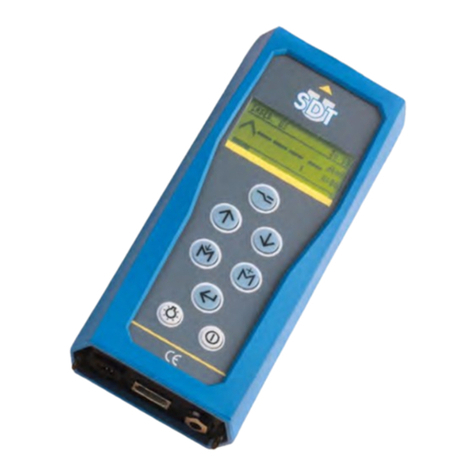
SDT SDT270 Pro 3 User manual

USER MANUAL
Version 10 - 2022
www.GlobalTestSupply.com
Find Quality Products Online at: sales@GlobalTestSupply.com

DC.R270.MAN.001--10--SDT270-user-manual-EN.docx
2/67
You can download the latest version of this manual by visiting the SDT International website:
•Due to typical self-discharge of NiMH batteries, it is recommended to charge the SDT270 battery at least every 3
months, even if it is not used.
•To check your SDT270 version, please refer to the chapter "System Info".
•Your SDT270 device proposes both text and icon interfaces. This manual describes only the icon interface. To switch
between icon and text interface, consult the topic Switch between icon and text interfaces.
www.GlobalTestSupply.com
Find Quality Products Online at: sales@GlobalTestSupply.com

DC.R270.MAN.001--10--SDT270-user-manual-EN.docx
3/67
Table of contents
Contents
1Introduction to the SDT270 6
1.1 SDT270: User and Application driven platform..................................................................................................................................... 6
1.2 SDT270 main features.......................................................................................................................................................................... 6
2SDT270 versions 7
2.1 Find your SDT270 version..................................................................................................................................................................... 7
2.2 SDT270 versions overview ................................................................................................................................................................... 7
2.3 Sensors, accessories and transmitters overview................................................................................................................................... 7
3SDT270 ATEX version 9
3.1 Specific safety precautions for SDT270 ATEX version............................................................................................................................ 9
3.2 ATEX marking ...................................................................................................................................................................................... 9
3.3 ATEX classification............................................................................................................................................................................... 9
3.4 SDT Sensors for SDT270 ATEX version .................................................................................................................................................. 9
4Safety precautions for the laser 10
5Charging the battery 11
5.1 SDT270 autonomy ............................................................................................................................................................................. 12
5.2 The SDT universal charger.................................................................................................................................................................. 12
6Turn on & turn off the SDT270 13
6.1 Turn on.............................................................................................................................................................................................. 13
6.2 Turn off ............................................................................................................................................................................................. 13
7Plug & unplug a sensor 14
7.1 Plug a sensor ..................................................................................................................................................................................... 14
7.2 Unplug a sensor................................................................................................................................................................................. 14
8Keyboard functions when taking a measurement 15
9Taking an ultrasonic measurement 16
9.1 Measurement type: static or dynamic................................................................................................................................................ 16
9.2 Measurement settings....................................................................................................................................................................... 16
9.3 Getting data ...................................................................................................................................................................................... 16
9.4 Saving Data ....................................................................................................................................................................................... 17
9.5 Modify the mixer frequency............................................................................................................................................................... 17
10 Taking a vibration measurement 18
10.1 Measurement type: static or dynamic................................................................................................................................................ 18
10.2 Measurement settings....................................................................................................................................................................... 18
10.2.1 Computation time............................................................................................................................................... 18
10.2.2 Frequency range .................................................................................................................................................19
10.3 Getting data ...................................................................................................................................................................................... 19
10.4 Saving Data ....................................................................................................................................................................................... 19
11 Taking a temperature measurement using the built-in thermometer 20
11.1 Laser.................................................................................................................................................................................................. 20
11.2 Settings ............................................................................................................................................................................................. 20
11.3 Getting and saving data ..................................................................................................................................................................... 20
12 Taking a rotational speed measurement using the built-in tachometer 21
12.1 Laser.................................................................................................................................................................................................. 21
12.2 Getting and saving data ..................................................................................................................................................................... 21
13 Viewing and deleting stored measurements 22
14 Planned and Conditional Survey modes 23
14.1 Planned survey mode ........................................................................................................................................................................ 23
www.GlobalTestSupply.com
Find Quality Products Online at: sales@GlobalTestSupply.com

DC.R270.MAN.001--10--SDT270-user-manual-EN.docx
4/67
14.1.1 Selecting the planned Survey mode for measurement storage .........................................................................23
14.1.2 Selecting the first Measurement ........................................................................................................................23
14.1.3 Viewing alarms attached to the Measurement ..................................................................................................24
14.1.4 Adding a message to the Measurement.............................................................................................................24
14.1.5 Setting up the SDT270 ........................................................................................................................................24
14.1.6 Getting and saving data...................................................................................................................................... 25
14.1.7 Selecting the next measurement........................................................................................................................25
14.1.8 Measurement in alarm .......................................................................................................................................26
14.1.9 End of survey ......................................................................................................................................................26
14.2 Conditional Survey mode................................................................................................................................................................... 26
14.2.1 Selecting the conditional Survey mode for measurement storage ....................................................................26
14.2.2 Selecting the first Measurement ........................................................................................................................27
14.2.3 Viewing alarms attached to the Measurement ..................................................................................................27
14.2.4 Adding a message to the Measurement.............................................................................................................27
14.2.5 Setting up the SDT270 ........................................................................................................................................28
14.2.6 Getting and saving data...................................................................................................................................... 28
14.2.7 Selecting the next measurement........................................................................................................................29
14.2.8 Measurement in alarm .......................................................................................................................................30
14.2.9 End of survey ......................................................................................................................................................30
15 SDT270 DataDump software 31
15.1 Install DataDump Application ............................................................................................................................................................ 31
15.1.1 Installation from the USB key .............................................................................................................................31
15.1.2 Online Installation............................................................................................................................................... 31
15.1.3 Starting up the installation .................................................................................................................................31
15.2 Activate DataDump software............................................................................................................................................................. 33
15.3 Download and erase stored data with DataDump .............................................................................................................................. 37
15.3.1 Erasing SDT270 memory.....................................................................................................................................38
16 Installation and activation of Updater software 39
16.1.1 Introduction........................................................................................................................................................39
16.2 Installation of SDT Updater application.............................................................................................................................................. 39
16.2.1 Retrieve the installer...........................................................................................................................................39
16.2.2 Setup...................................................................................................................................................................39
16.3 Activate Updater software................................................................................................................................................................. 43
17 Updating & upgrading your SDT270 47
17.1 Updating & upgrading your SDT270 using the "SDT270 Updater" software (for SDT270 SB and SS device versions)............................. 47
17.1.1 Updating ............................................................................................................................................................. 47
17.1.2 Upgrading ........................................................................................................................................................... 48
17.2 Updating & upgrading your SDT270 using DataDump software (for SDT270 SD and DD device versions)............................................. 49
17.2.1 Updating ............................................................................................................................................................. 49
17.2.2 Upgrading ........................................................................................................................................................... 50
17.3 Updating & upgrading your SDT270 using the "Ultranalysis Suite" software (for SDT270 SU and DU device versions) ......................... 51
17.3.1 Updating ............................................................................................................................................................. 52
17.3.2 Upgrading ........................................................................................................................................................... 52
18 Keyboard functions when navigating inside the menus 55
19 Switch between icon and text interfaces 56
20 Network settings 57
21 Settings 58
www.GlobalTestSupply.com
Find Quality Products Online at: sales@GlobalTestSupply.com

DC.R270.MAN.001--10--SDT270-user-manual-EN.docx
5/67
22 System Info 59
23 SDT270 & SDT200 navigation icons list* 62
23.1 Measurement screen icons ................................................................................................................................................................ 62
23.2 Miscellaneous function key icons....................................................................................................................................................... 63
23.3 Main menu icons ............................................................................................................................................................................... 63
24 Recommended calibration intervals 65
25 EU Directives and Standards 66
26 Warranty 66
27 Responsibility limits 66
28 Destruction and recycling of waste equipment 67
29 Copyright 67
www.GlobalTestSupply.com
Find Quality Products Online at: sales@GlobalTestSupply.com

DC.R270.MAN.001--10--SDT270-user-manual-EN.docx
6/67
SDT270 overview and sa fety informat ion
1Introduction to the SDT270
1.1 SDT270: User and Application driven platform
The SDT270 is a portable ultrasound device dedicated to Predictive Maintenance and Energy saving, covering a wide
range of applications, meeting the needs of the Maintenance Departments.
At SDT we recognize each customer’s ultrasound needs are as unique as they are. So, the SDT270 is proposed with 6
versions, and you have the possibility to build your custom Kit configured to meet your specific needs.
The SDT270 remains true to our reputation for intelligent instrument design: your device is upgradeable which means
that you can add functionalities, sensors, software, and accessories as and when you need it. So, your investment in
your SDT270 will be paying you back for years to come.
The SDT270 is a User oriented platform that fits on the competencies of each operator. Thus, you will be able to work
out an individual program of data collection survey adapted to the skills of everyone. The operator will simply choose
his personalized program after logging himself in. The SDT270 in combination with Ultranalysis Suite squares the circle
of maintaining simplicity for those who need it, while providing sophistication for those who want it.
1.2 SDT270 main features
We at SDT are very proud of the 270. You are now the owner of an instrument that:
•Measures broadband ultrasound signals with a 100kHz bandwidth
•Realizes data acquisition with a 250kHz sampling frequency
•Uses long-duration time sampling and data streaming
•Integrates built-in thermometer and tachometer with a laser
•Includes a SQL database.
•Includes an Operator logging in.
•Insures full measurement traceability from Operator to sensor.
•Warns the Operator when an alarm is triggered
•Is IP (Internet) addressable
•Is remotely controlled and operated
•Incorporate 2 measurement channels.
www.GlobalTestSupply.com
Find Quality Products Online at: sales@GlobalTestSupply.com

DC.R270.MAN.001--10--SDT270-user-manual-EN.docx
7/67
2SDT270 versions
Your device is upgradeable which means that you can add functionalities, sensors, software,
and accessories as and when you need it. So, your investment in your SDT270 will be paying
you back for years to come.
2.1 Find your SDT270 version
To check your SDT270 version, please refer to the chapter "System Info".
2.2 SDT270 versions overview
SB
SS
SD
SU
DD
DU
MEASUREMENTS
Static
✓
✓
✓
✓
✓
✓
Dynamic
✓
✓
MEMORY
Generic 100 node tree
✓
✓
✓
Unlimited user-defined tree
✓
✓
SOFTWARE
DataDump application
✓
✓
Ultranalysis suite 3 (UAS3)
✓
✓
✓
✓
✓
✓
AVAILABLE OPTIONS
Built-in thermometer
*
*
*
*
*
*
Built-in tachometer
*
*
*
*
*
*
Accelerometer interface
*
*
*
*
*
*
2.3 Sensors, accessories and transmitters overview
Applications
Airborne
leak
detection
Lubrication
control
Machine
monitoring
Steam trap &
valve
inspection
Electrical
inspection
Tightness
testing
Sensors
Internal US sensor
✓
✓
✓
✓
✓
✓
Flexible sensor
✓
✓
✓
✓
✓
Parabolic sensors paraDish1
and 2
✓
✓
Needle sensor RS1N/RS2N
✓
✓
✓
Threaded sensor RS1T/RS2T
✓
✓
✓
✓
www.GlobalTestSupply.com
Find Quality Products Online at: sales@GlobalTestSupply.com

DC.R270.MAN.001--10--SDT270-user-manual-EN.docx
8/67
ICP accelerometer
✓
✓
Built-in thermometer
✓
✓
✓
Built-in tachometer
✓
✓
Accessories
Acoustic cones EDS 1 & 2
✓
✓
✓
Mounting pad (*)
✓
✓
Flat magnetic foot (*)
✓
✓
✓
✓
Curved magnetic foot (*)
✓
✓
✓
✓
Needle (*)
✓
Transmitters
Bi-sonic 200 mW
transmitter
✓
Multi transmitter
SDT8MS
✓
T-Sonic 1
✓
T-Sonic 9
✓
Airborne
leak
detection
Lubrication
control
Machine
monitoring
Steam trap &
valve
inspection
Electrical
inspection
Tightness
testing
(*) The mounting pad, the flat magnetic foot and the curved magnetic foot are the accessories of the Threaded sensor
RS1T and the Accelerometer.
The Needle is an accessory of the Accelerometer:
www.GlobalTestSupply.com
Find Quality Products Online at: sales@GlobalTestSupply.com

DC.R270.MAN.001--10--SDT270-user-manual-EN.docx
9/67
3SDT270 ATEX version
Please read carefully the safety precautions before using the SDT270 - ATEX
version in a potentially explosive environment.
3.1 Specific safety precautions for SDT270 ATEX version
•Make sure your SDT270A protection class is suited regarding the environment it
will be used.
•Under no circumstances, do not attempt to service or replace SDT270 ATEX
version components. In case of malfunction, contact SDT International or SDT
local representative.
•Maintenance must always be performed outside potentially explosive
environments.
•Battery charge must exclusively be performed outside potentially explosive
environments.
•FUBATTR270A is the only authorized power source for SDT270 ATEX version.
•The max. permissible room temperature is:
o-15°C to 48°C for T3.
o-15°C to 60°C for T2.
•Do not use USB connectivity in dangerous area.
•Do not use SDT carrying case in dangerous area
•Potential danger of static electricity for the display. Avoid electrostatic charge:
oAvoid friction.
oNo dry cleaning.
3.2 ATEX marking
The SDT270 ATEX version is recognizable by its specific marking located in its back plate:
3.3 ATEX classification
The SDT270A ATEX version is classified II 1 G Ex ia IIC T3/T2 Ga. The ISSEP ATEX
certificate is available on demand.
3.4 SDT Sensors for SDT270 ATEX version
The SDT270 is working with all SDT Sensors, but only the Flexible sensor ATEX and the Needle RS1 ATEX can be used in
hazardous areas.
While working in potentially explosive environment, use only ATEX sensor tip on flexible
rod, ATEX ParaDish2, ATEX RS1N needle contact sensor, or ATEX RS1T threaded contact
sensor.
www.GlobalTestSupply.com
Find Quality Products Online at: sales@GlobalTestSupply.com

DC.R270.MAN.001--10--SDT270-user-manual-EN.docx
10/67
4Safety precautions for the laser
The SDT270 is equipped with a class 2 laser: risk of eye injury:
•Never look directly to the laser beam
•Never point the laser beam at a person’ eye
•Do not aim the laser at specular reflective surfaces
•Never view the laser using an optical instrument.
www.GlobalTestSupply.com
Find Quality Products Online at: sales@GlobalTestSupply.com

DC.R270.MAN.001--10--SDT270-user-manual-EN.docx
11/67
Getting started
5Charging the battery
If you have just taken your SDT270 and this manual out of the box for the first time, please put your 270 on charge now.
The SDT270 uses an internal NiMH battery. The battery charger outlet will connect to a socket on the rear side of the
270.
Battery charge of the SDT270 ATEX must exclusively be performed outside potentially
explosive environments.
Only use the charger provided by SDT.
The charging time will typically be 6 hours. When the Led of the charger is off, the SDT270 battery is completely
charged.
Like most batteries these days, leaving the 270 charging after the charger says it is charged does not hurt the battery –
in fact it very slowly tops the charge up a little more.
You can charge the SDT270 switched off. You can also trickle charge the SDT270 switched on, so
you can be using it to load and unload data, for example, and charge it at the same time.
SDT270 rear side
SDT270 with its battery loader
For a device that has been discharged for several days/weeks or in case of a problem encountered during charging,
follow the procedure below to force a full charge cycle:
1. Connect the device to the charger;
2. Do a "RESET" by pushing the switch with a paper clip in the small hole above the audio output (see
red circle in the "rear side" picture above);
3. Wait at least 4 hours for a full charge before turning the device on again. The green LED should be lit
continuously.
When a charge cycle is complete, the counter available in the System Info/Battery Info menu is incremented by +1.
*
* Serial number / Number of cycles
Serial Number
Number of cycles
www.GlobalTestSupply.com
Find Quality Products Online at: sales@GlobalTestSupply.com

DC.R270.MAN.001--10--SDT270-user-manual-EN.docx
12/67
Please note that the device must be turned off to charge the battery.
•When the device is turned on, the charger supplies power directly to the device without charging the battery.
Before storing the device for a long period of time, it is recommended to fully charge the battery.
•There is no specific battery for the "real time clock", and it is powered by the battery pack.
5.1 SDT270 autonomy
A fully charged battery will give you about 8 hours of continuous use. This will vary of course depending upon your need
to use the backlight and the power drain of certain external sensors that you might be using.
•You can increase the autonomy by more than 20% by disabling the LAN when your
device is not connected to a network Check out Network setting chapter to find how to
disable LAN function. You are able also to set an Auto Power Down and a time before
switching off the backlight.
•You can also save battery power by setting the device's automatic shutdown in the
device's settings. With this option, the equipment will turn off after the set time.
•In the same way, it is possible to set the delay of the screen backlight, accessing the
device settings.
5.2 The SDT universal charger
Charger type:
Specific for SDT170, SDT200 and SDT270 NiMH battery pack
Use:
Indoor use only; ambient temperature: min 0°C, max 45°C.
Mode of operation: continuous.
Environment pollution: max degree 2.
Altitude during operation: max 2000 m.
Power supply:
230 VAC or 110 VAC +6 % / -10 %, 50/60 Hz, 25 VA,
max branch fuse 20 A
Status indicator:
•Green LED is continuously lit: battery is fully charged
•Green LED flashes evenly: normal charge
•One red flash every 5 seconds: Battery Voltage error
•Two red flashes every 5 seconds: Over temperature error
•Three red flashes every 5 seconds: Timeout full charge
•Four red flashes every 5 seconds: Timeout Rapid charging
•Five red flashes every 5 seconds: Timeout Activate charging
•Six red flashes every 5 seconds: Communication error
Input fuse:
T1.6 A (intern, not user replaceable)
Protection:
Temperature protected, limit set at 60°C / 140°F
Output voltage:
Between +4.0 and 14.5 V DC (depending on the operating mode)
Output Current:
Max 1 A
Output Power:
Max 7 W
Isolation:
Class II double isolation
Main supply transformer:
Class II, switching mode regulation
www.GlobalTestSupply.com
Find Quality Products Online at: sales@GlobalTestSupply.com

DC.R270.MAN.001--10--SDT270-user-manual-EN.docx
13/67
Overvoltage Category:
II
EMC:
EN 61000-4, EN 61000-3, EN 61010-1
Electrical safety (LVD):
EN 60950-1:2007
UL 60950-1, ed2(2005)
Weight:
300 grams / 10.6 ounces
Housing:
PPE
Protection Class:
IP40
6Turn on & turn off the SDT270
6.1 Turn on
To turn on the SDT270, press the Power button on the bottom right of the keypad. The status LED shines bright blue
and then seconds later you will see on the screen the message “System boot up”. If you do not see this display your
battery might be flat.
6.2 Turn off
To turn off the SDT270, push the Power button on the bottom right of the keypad. You will see the following screen:
Press enter to shut down or another key to continue” on the screen. Press the Enter button to shut down the device.
www.GlobalTestSupply.com
Find Quality Products Online at: sales@GlobalTestSupply.com

DC.R270.MAN.001--10--SDT270-user-manual-EN.docx
14/67
7Plug & unplug a sensor
7.1 Plug a sensor
The SDT270 has two measurements channels for external sensors:
•The first one is equipped with a black collar. It corresponds to the B choice on the display. The black collar
LEMO is reserved for ultrasonic and Mass Flow sensors.
•The second one with a red collar. It corresponds to the R choice on the display. The Red collar LEMO connector
is reserved for accelerometers.
The connections for external sensors are LEMO connectors. They are a commonly used industrial connector, considered
for their reliability and their robustness. They have a sprung-loaded knurled barrel and mechanical polarization to go
only in one way round
To plug a LEMO connector:
•Line up the red dot on the plug with the red mark on the connector.
•Insert the plug into the connector without any rotating movement.
When an external sensor is connected to the SDT270, it is automatically selected. However, you can switch between
available sensors using the F1 button.
7.2 Unplug a sensor
To unplug the LEMO connector
•Move up, towards the cable, the ring located on the bottom of the plug.
•Only pull the connector without any rotation.
Please, never pull on the cable itself.
www.GlobalTestSupply.com
Find Quality Products Online at: sales@GlobalTestSupply.com

DC.R270.MAN.001--10--SDT270-user-manual-EN.docx
15/67
8Keyboard functions when taking a
measurement
•F1 to select a sensor.
•F2 to select a measurement type
•F3 to adjust the settings for the sensor in use.
•Disc button to save measurements.
•M button to start the measurement acquisition.
•Up and down arrows to increase and decrease amplification (used for US sensors).
•Left and right arrows to decrease and increase the audio volume of the headphones.
•Enter to access to the menus.
www.GlobalTestSupply.com
Find Quality Products Online at: sales@GlobalTestSupply.com

DC.R270.MAN.001--10--SDT270-user-manual-EN.docx
16/67
9Taking an ultrasonic measurement
External Ultrasonic sensors must be connected to the black collar LEMO connector.
Select the desired ultrasonic sensor using F1 button, if necessary.
Set up amplification using Up and Down arrow buttons, till the up and down amplification adjustment indicators
disappear.
Set up the headphone volume using Left and Right arrows.
9.1 Measurement type: static or dynamic
This feature is available on the SDT270 DD and DU versions. To check your SDT270 version, please refer to the chapter
"System Info".
Press the F2 button, the following screen appears:
Choose the static icon, using direction arrows to collect a static measurement. Validate by Enter
Choose the dynamic icon, using direction arrows, to collect a dynamic measurement. Validate by Enter
9.2 Measurement settings
Press the F3 button to enter the measurement settings menu.
Select and then adjust the computation time using Up and Down arrow buttons.
The computation time is adjustable from 0 to 100 seconds.
The RMS, Max RMS, Peak and Crest Factor are calculated over the total computation time.
Use the F1 button to save the settings as a preferred configuration
Use the F2 button to load your preferred configuration
Use the F3 button to use a one-shot configuration, without saving it.
9.3 Getting data
Press the M button.
www.GlobalTestSupply.com
Find Quality Products Online at: sales@GlobalTestSupply.com

DC.R270.MAN.001--10--SDT270-user-manual-EN.docx
17/67
At the end of the computation time, a screen detailing RMS, Max RMS, Peak and Crest factor values, is displayed:
Press the F1 button to come back to the measurement screen without saving.
9.4 Saving Data
This feature is not available on the SDT270 SB version. To check your SDT270 version, please refer to the chapter
"System Info".
At the end of the computation time, press the Store button to save the data.
Then choose the desired memory location using the Up and Down arrow buttons and confirm by pressing the Enter
button.
9.5 Modify the mixer frequency
Press F2, select the icon then press Enter.
The mixer frequency is adjustable from 10 kHz to 128 kHz by using F1 to decrease the frequency and F3 to increase it.
www.GlobalTestSupply.com
Find Quality Products Online at: sales@GlobalTestSupply.com

DC.R270.MAN.001--10--SDT270-user-manual-EN.docx
18/67
10 Taking a vibration measurement
This requires optional accessories and firmware key.
The accelerometer must be connected to the red collar LEMO connector.
Select the accelerometer using F1 button, if necessary.
Set up the headphone volume using Left and Right arrows.
10.1 Measurement type: static or dynamic
This feature is available on the SDT270 DD and DU versions. To check your SDT270 version, please refer to the chapter
"System Info".
Press the F2 button, the following screen appears:
Choose the static icon, using direction arrows to collect a static measurement. Validate by Enter
Choose the dynamic icon, using direction arrows, to collect a dynamic measurement. Validate by Enter
10.2 Measurement settings
Press the F3 button to enter the measurement settings menu.
10.2.1 Computation time
Select and then adjust the computation time using Up and Down arrow buttons.
The computation time is adjustable from 0 to 60 seconds.
www.GlobalTestSupply.com
Find Quality Products Online at: sales@GlobalTestSupply.com

DC.R270.MAN.001--10--SDT270-user-manual-EN.docx
19/67
The acceleration and velocity RMS, the acceleration Peak and Crest Factor are calculated over the total computation
time.
10.2.2 Frequency range
Select and adjust the frequency range. The available ranges are from 10 to 1000 Hz and from 10 to 10000 Hz.
Use the F1 button to save the settings as a preferred configuration
Use the F2 button to load your preferred configuration
Use the F3 button to use a one-shot configuration, without saving it.
10.3 Getting data
Press the M button.
At the end of the computation time, a screen detailing acceleration and velocity RMS, acceleration Peak and Crest factor
values, is displayed:
Press the F1 button to come back to the measurement screen without saving.
10.4 Saving Data
This feature is not available on the SDT270 SB version. To check your SDT270 version, please refer to the chapter
"System Info".
At the end of the computation time, press the Store button to save the data or F1 to come back to the measurement
screen without saving.
When saving, choose the desired memory location using the Up and Down arrow buttons and confirm by pressing the
Enter button.
www.GlobalTestSupply.com
Find Quality Products Online at: sales@GlobalTestSupply.com

DC.R270.MAN.001--10--SDT270-user-manual-EN.docx
20/67
11 Taking a temperature measurement
using the built-in thermometer
This feature is available when the option T is activated.
Select the built-in thermometer by highlighting the T in the upper left corner of the display with F1.
11.1 Laser
Press F2 to activate the laser. The message on the bottom right of the display indicates the status of the function. So, in
the example shown below, the laser is off.
11.2 Settings
Press F3 to select:
The physical unit. The choice is Celsius, Kelvin, Rankin, Fahrenheit.
The emissivity coefficient from 0.01 to 1.
Use the F1 button to save the settings as a preferred configuration
Use the F2 button to load your preferred configuration
Use the F3 button to use a one-shot configuration, without saving it.
11.3 Getting and saving data
The data recording function is not available on the SDT270 SB version. To check your SDT270 version, please refer to the
chapter "System Info".
Press the M button to freeze a measurement.
Press the Store button to save the data or F1 to come back to the measurement screen without saving.
When saving, choose the desired memory location using the Up and Down arrow buttons and confirm by pressing the
Enter button.
www.GlobalTestSupply.com
Find Quality Products Online at: sales@GlobalTestSupply.com
This manual suits for next models
2
Table of contents
Other SDT Measuring Instrument manuals
Popular Measuring Instrument manuals by other brands
PCB Piezotronics
PCB Piezotronics TLB356A12 Installation and operating manual

Kurz
Kurz 454FTB Startup guide
Klein Tools
Klein Tools VDV500-123 Probe-Pro instruction manual
BW SENSING
BW SENSING BWM826 Technical manual

Honeywell
Honeywell DR4300 Series Replacement instructions

PCB Piezotronics
PCB Piezotronics SM101A06 Installation and operating manual
