logo
Brands
  1. Home
  2. •
  3. Brands
  4. •
  5. Sealey
  6. •
  7. Measuring Instrument
  8. •
  9. Sealey TP91300.V2 User manual

Sealey TP91300.V2 User manual

Other Sealey Measuring Instrument manuals

Sealey VS0052 User manual

Sealey

Sealey VS0052 User manual

Sealey VS0560.V2 User manual

Sealey

Sealey VS0560.V2 User manual

Sealey VS0567 User manual

Sealey

Sealey VS0567 User manual

Sealey GA450 User manual

Sealey

Sealey GA450 User manual

Sealey GA45 User manual

Sealey

Sealey GA45 User manual

Sealey AUTO SERVICE TA060 User manual

Sealey

Sealey AUTO SERVICE TA060 User manual

Sealey 6-24V AUTO PROBE PLUS User manual

Sealey

Sealey 6-24V AUTO PROBE PLUS User manual

Sealey VS0563 User manual

Sealey

Sealey VS0563 User manual

Sealey TA304 User manual

Sealey

Sealey TA304 User manual

Sealey TA102 User manual

Sealey

Sealey TA102 User manual

Sealey MS100 User manual

Sealey

Sealey MS100 User manual

Sealey Auto Service Line VS0565 User manual

Sealey

Sealey Auto Service Line VS0565 User manual

Sealey VS602 User manual

Sealey

Sealey VS602 User manual

Sealey VS212.V3 Firmware update

Sealey

Sealey VS212.V3 Firmware update

Sealey SA37/93.V3 User manual

Sealey

Sealey SA37/93.V3 User manual

Sealey PPLK User manual

Sealey

Sealey PPLK User manual

Sealey AK9636D.V2 User manual

Sealey

Sealey AK9636D.V2 User manual

Sealey Auto Service Series User manual

Sealey

Sealey Auto Service Series User manual

Sealey AK9636D.V2 User manual

Sealey

Sealey AK9636D.V2 User manual

Sealey GA70CR User manual

Sealey

Sealey GA70CR User manual

Sealey SA9302 User manual

Sealey

Sealey SA9302 User manual

Sealey MM19.V3 User manual

Sealey

Sealey MM19.V3 User manual

Sealey AK9635D.V3 User manual

Sealey

Sealey AK9635D.V3 User manual

Sealey TA303 User manual

Sealey

Sealey TA303 User manual

Popular Measuring Instrument manuals by other brands

Suaoki D40 user manual

Suaoki

Suaoki D40 user manual

Elster BK-G1.6 operating instructions

Elster

Elster BK-G1.6 operating instructions

Endress+Hauser Deltabar FMD71 technical information

Endress+Hauser

Endress+Hauser Deltabar FMD71 technical information

Duratool D03128 manual

Duratool

Duratool D03128 manual

Vega VEGAPULS 65 Quick setup guide

Vega

Vega VEGAPULS 65 Quick setup guide

Tonghui TH2618B Operation manual

Tonghui

Tonghui TH2618B Operation manual

Tenmars TM-801 user manual

Tenmars

Tenmars TM-801 user manual

MSR 145 user manual

MSR

MSR 145 user manual

TPS WP-82 manual

TPS

TPS WP-82 manual

PCB Piezotronics 003C30 Installation and operating manual

PCB Piezotronics

PCB Piezotronics 003C30 Installation and operating manual

Tenma 72-10465 manual

Tenma

Tenma 72-10465 manual

Endress+Hauser Proline Promag 50 Brief operating instructions

Endress+Hauser

Endress+Hauser Proline Promag 50 Brief operating instructions

Siemens SITRANS F Coriolis FCT030 Function manual

Siemens

Siemens SITRANS F Coriolis FCT030 Function manual

KLINGER CMF V Series instruction manual

KLINGER

KLINGER CMF V Series instruction manual

Keysight M8290A Getting started guide

Keysight

Keysight M8290A Getting started guide

Acterna MS1400 Operation manual

Acterna

Acterna MS1400 Operation manual

R&S ZPH manual

R&S

R&S ZPH manual

Datacolor ColorReader DC10-2 user guide

Datacolor

Datacolor ColorReader DC10-2 user guide

https://manuals.online logo
https://manuals.online logoBrands
  • About & Mission
  • Contact us
  • Privacy Policy
  • Terms and Conditions

Copyright 2025 Manuals.Online. All Rights Reserved.

INSTRUCTIONS FOR:
DIESEL & FLUID FLOW METER
MODEL No: TP91300.V2
Thank you for purchasing a Sealey product. Manufactured to a high standard this product will, if used according to these instructions and properly
maintained, give you years of trouble free performance.
IMPORTANT: PLEASE READ THESE INSTRUCTIONS CAREFULLY. NOTE THE SAFE OPERATIONAL REQUIREMENTS, WARNINGS AND CAUTIONS.
USE THIS PRODUCT CORRECTLYAND ONLY FOR ITS INTENDED PURPOSE. FAILURE TO DO SO MAY CAUSE DAMAGE AND/OR PERSONAL INJURY
AND WILL INVALIDATE THE WARRANTY. RETAIN THESE INSTRUCTIONS FOR FUTURE USE.
 Maintain the meter in good condition (use an authorised service agent).
Replace or repair damaged parts. Use recommended parts only. Unauthorised parts may be dangerous and will invalidate the warranty.
Keep the meter clean for the safest and best performance.
 Ensure that a fuel filter is securely attached to any pick up pipe so that unfiltered fuel is not taken through the meter.
 Wear safety goggles, gloves and protective clothing when working around fuel. A full range of personal safety equipment is available from your
local Sealey dealer.
Use the meter in a suitable work area. Keep area clean and tidy and free from unrelated materials and ensure there is adequate lighting.
 Maintain correct balance and footing. Ensure the floor is not slippery and wear non-slip shoes.
Keep children and unauthorised persons away from the work area.
 DO NOT use the meter and any associated pump where explosive or flammable vapours may be present.
 WARNING! DO NOT pump the following fluids through the flow meter: Petrol, flammable liquids with Flashpoint <55°C, water, liquids with
viscosity >20 cSt, corrosive chemicals and solvents.
1. SAFETY INSTRUCTIONS
2. INTRODUCTION AND SPECIFICATION
3. INSTALLATION
Introduction:
Volumetric nutating disc meter with three digit resettable display and six
digit total display. Unique filter and flange assembly allows meter to be
positioned in four configurations. Suitable for use with all Sealey brand
diesel & fluid transfer pumps.
Specification:
Working pressure: ...................................................................0.1 - 3.5 Bar
Operating Temp:......................................................................-10 to +50ºC
Precision:.......................................................................................... +/- 1%
Flow Rate: .............................................................................20 - 80 ltr/min
Partial Indicator:.........................................................................max 999 ltr
Total indicator: .....................................................................max 999999 ltr
Resolution:..........................................................................................0.1 ltr
Weight: ...............................................................................................1.5kg
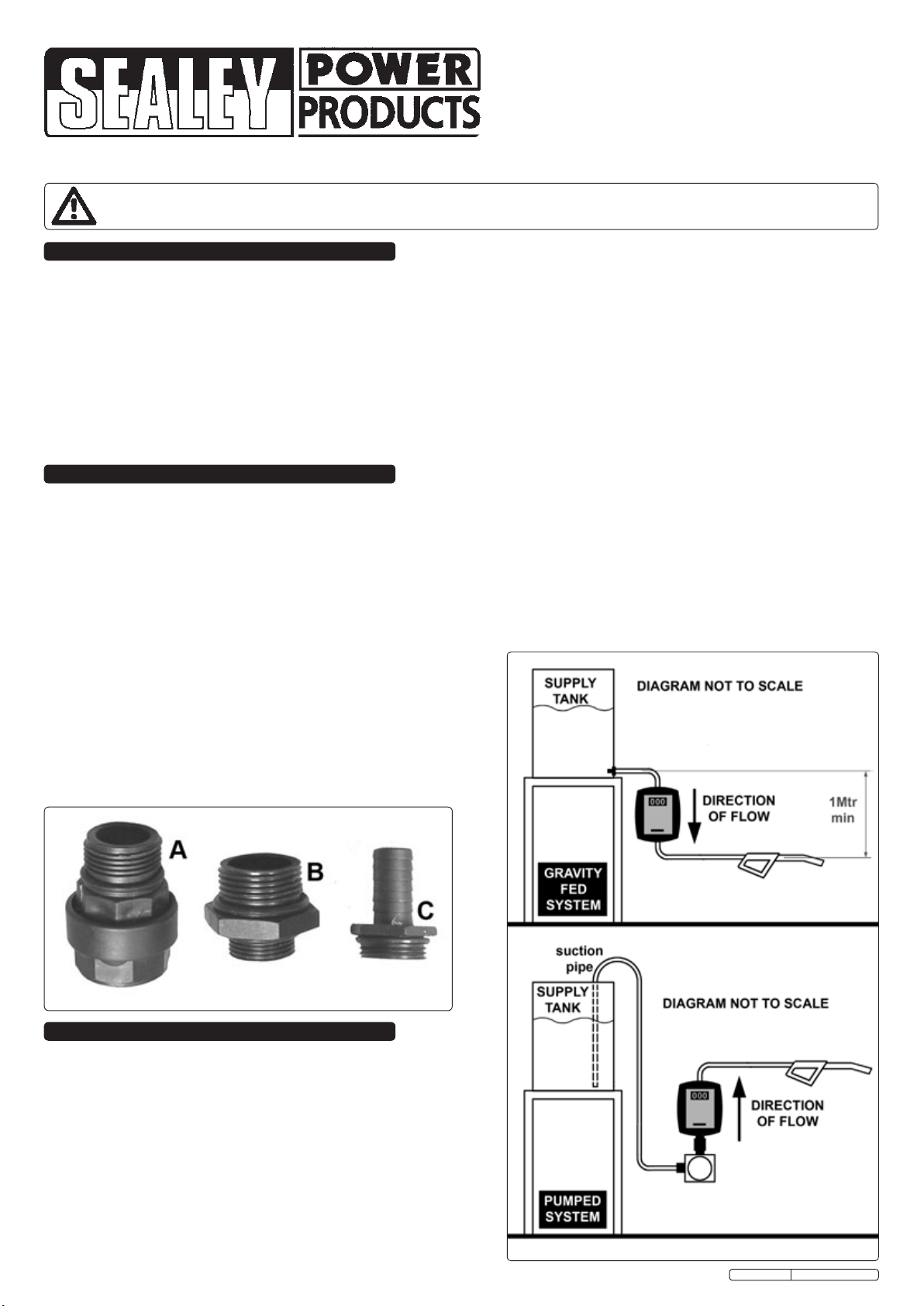
Accessories:
A- Swivel adaptor B- Pump connector
C- Outlet connector
TP91300.V2 Issue: 1 - 18/07/11
Original Language Version
3.2.4 Following installation and setting, (see section.3.3) the meter is
ready for use. To reset the partial counter to zero, rotate the reset
knob clockwise.
3.2.5 Constructed for operation at a maximum pressure of 3.5 bar (50
PSI), the meter must be mounted in a such way that no unfiltered
liquid or air is pumped through it. In the case of gravitational
systems (without pumps), there must be a difference in height of at
least 1 metre between the outlet of the tank and the delivery gun
to ensure optimum operation.
fig.1
fig.2
fig.3
3.1 Installation options.
The TP91300.V2 flow meter can be used in both gravity fed
systems (see fig.2) and circuits with motor pumps (see fig.3) or
manual circuits equipped with a by-pass (not illustrated). In any
particular installation, attention must be paid to the direction of flow
through the meter as indicated by the moulded in arrows on the
back of the unit. If the required installation will result in the meter
readout being upside down it is possible to turn the face through
180º to correct this situation as described below.
3.2 Slide the reset knob from its shaft.
3.2.1 Undo both small crosshead screws at the sides of the plastic body.
3.2.2 Undo the four allen headed bolts at the back of the meter (fig.4)
and prise off the back of the meter and rotate through 180°
3.2.3 Reassemble in the reverse order of the above.
Original Language Version
3.5 Resetting.
The meter has been set at the factory to a pressure of 1.5 bar,
(21PSI) whilst transferring Diesel oil. As the operating pressure is
a fundamental factor for the measurement mechanism, it is
recommended that the meter is reset every time different
pressures and/or liquids are used. The meter must also be reset
every time it is disassembled for maintenance.
3.5.1 Unscrew the setting plug (screw A in fig.7).
3.5.2 Start the flow by opening a valve or starting a pump then stop the
flow of liquid by closing the delivery gun without stopping the
flow.
3.5.3 Set the partial indicator to zero.
3.5.4 Perform the delivery at the flow rate for which the precision is
required by transferring it into a container calibrated for no less
than 20 litres.
3.5.5 Compare the value indicated on the partial/total counter with the
volume in the container (the real value).
3.5.6 Turn the adjustment screw (B in fig.7 ) clockwise if the value is
lower and counter-clockwise if the value is higher.
3.5.7 Repeat operation 4 until the measurement is satisfactory.
3.5.8 Screw the setting plug (screw A) back into place.
fig.4 fig.6
fig.7
3.3 Mounting to a pump. (fig.3 & 5)
3.3.1 The TP91300.V2 flow meter can be directly mounted onto a pump
outlet as shown in fig.6.
3.3.2 Before mounting the pump, check the required direction of flow and
if necessary rotate the face of the meter as described in section 3.2.
3.3.3 Screw pump mounting adaptor 'B' into the pump outlet port
ensuring that it is sealed with a suitable 'O' ring or PTFE tape.
3.3.4 Screw the outlet connector 'C' into the meter outlet port ensuring
that it is sealed with a suitable 'O' ring or PTFE tape.
3.3.5 Screw the swivel adaptor 'A' into the meter inlet port ensuring that
it is sealed with a suitable 'O' ring.
3.3.6 Place the whole assembly onto the pump outlet fitting and rotate
the main body of the adaptor to screw it down onto the pump.
Before finally tightening the fitting, rotate the meter on the fitting to
point in the desired direction and tighten the fitting.
3.4 In-line Mounting. (ref. fig.2)
3.4.1 When mounted in an in-line situation the TP91300.V2 flow meter
must still be rigidly mounted for safe and accurate performance.
Once the meter is properly fixed it can be connected via rigid or
flexible pipework that is suitable for the liquid flowing through it.
fig.5
TP91300.V2 Issue: 1 - 18/07/11
4. TROUBLESHOOTING
PROBLEM POSSIBLE CAUSE SOLUTION
Unsatisfactory precision Incorrect setting Reset (see above)
Measurement chamber dirty or clogged Clean measurement chamber
Presence of air in liquid Identify and eliminate leaks in suction lines or add foot
valve
Low ow Measurement chamber dirty or clogged Clean measurement chamber
Filter dirty or clogged Clean filter
Parts support is available for this product.
To obtain a parts listing and/or diagram, please log on to www.sealey.co.uk, email sales@sealey.co.uk or phone 01284 757500.
Original Language Version
NOTE: It is our policy to continually improve products and as such we reserve the right to alter data, specifications and component parts without prior notice.
IMPORTANT: No liability is accepted for incorrect use of this product.
WARRANTY: Guarantee is 12 months from purchase date, proof of which will be required for any claim.
INFORMATION: For a copy of our latest catalogue and promotions call us on 01284 757525 and leave your full name and address, including postcode.
01284 757500
01284 703534
sales@sealey.co.uk
Sole UK Distributor, Sealey Group,
Kempson Way, Suffolk Business Park,
Bury St. Edmunds, Suffolk,
IP32 7AR
www.sealey.co.uk
Web
email
TP91300.V2 Issue: 1 - 18/07/11