4. OPERATION
4.1. OVERVIEW OF COMPRESSION TESTING.
Whenanengine’sperformanceisdown,orifmisringoccurswhichcannotbeattributedtotheignitionorfuelsystems,a
compression test can provide diagnostic clues as to the engine’s condition.
Compressionshouldbuildupquicklyinahealthyengine.Averylowcompressionreadingontherststroke,followedbygradually
increasingpressureonsuccessivestrokes,indicateswornpistonrings.Alowcompressionreadingontherststroke,whichdoes
not build up during successive strokes, indicates leaking valves or a faulty head gasket (a cracked head could also be the cause).
Deposits on the undersides of the valve heads can also cause low compression. If the pressure in any cylinder is considerably
lower than the others, introduce a small quantity of clean oil into that cylinder through the glow plug hole, and repeat the test. If
the addition of oil temporarily improves the compression pressure, this indicates that bore or piston wear is responsible
for the pressure loss. If there is no improvement, it suggests that the leakage is around the valves, or a faulty head gasket.
A low reading from two adjacent cylinders suggests a faulty head gasket between the two cylinders. The presence of coolant in
theengineoilwillconrmthis.Ifthecompressionisunusuallyhigh,thecombustionchambersareprobablycoatedwith
carbon deposits. If this is the case, the cylinder head should be removed and de-carbonised.
As a rough guide, engines having a compression pressure in excess of 100psi (6.9 bar), should not exceed a compression loss of
more than 10psi (0.69 bar). On older engines with lower compression pressure, loss should not exceed 0.35 bar (5psi).
4.2. COMPRESSION TESTING.
4.2.1. Check the engine oil is at the correct level.
4.2.2. Remove all of the glow plugs from the engine.
4.2.3. Selecttheapplicableadaptorfromoneoftheaccompanyingkitsandscrewitintotherstglowplugport,ensuringthereisagood
sealwiththeO-ring(iftted).Connectthecouplingonthepressuregaugehosetotheadaptor,ensuringitlocksintoplace.
4.2.4. Turn over the engine using the starter motor and observe the gauge, looking for a steady increase in the reading (see 4.1) and note
the maximum reading obtained. Refer to the vehicle/engine manufacturer’s workshop manual for compression results data.
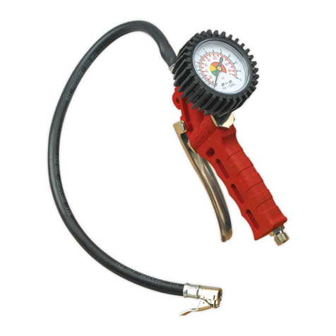
4.2.5. Depress the Re-set Valve (situated under the gauge) to release the pressure. The Re-set Valve allows the test to be repeated if
required without disconnecting the tester from the glow plug port.
WARNING! Always release pressure via the Re-set Valve BEFORE disconnecting the Tester.
4.2.6. Disconnect the compression tester from the adaptor and remove the adaptor from the glow plug port. Install them into the next
cylinder’s glow plug port and repeat the tests. Continue the tests for all of the remaining cylinders in turn.
NOTE: A variation in compression readings between cylinders is often a better indication of engine problems than the individual values of
compression.
4.3. TDC Indicator Tool.
4.3.1. Remove the glow plug from cylinder number 1. It may also be necessary to remove all glow plugs to facilitate manual turning over
of the engine.
4.3.2. Select the applicable adaptor from one of the accompanying kits and screw it into the glow plug port of cylinder number 1. Ensure
thatthereisagoodsealwiththeO-ring(iftted).ConnectthecouplingontheTDCndertotheadaptor,ensuringitlocksinto
place.
4.3.3. Position the indicator in a vertical position, in a suitable viewable location, using the magnetic hook if needed.
4.3.4. Turn the engine over manually, using a spanner or socket on the crankshaft pulley, in the direction of engine rotation and watch for
theoattoriseinthetube.Asthepistonrisesonthecompressionstroke,theoatwillrisetothetopofthetubeandstaythere,
whenthepistongoespastTDCandcompressionislost,theoatwillsuddenlysink.Notepositionandtemporarilymake
suitable marks to indicate TDC, or compare with existing timing marks.
4.3.5. Turntheengineoverafurther1¾turnsandtheoatshouldstarttoriseagainasthepistonrisesonthecompressionstroke.
ContinuetoslowlyturnthecrankshafttowardsTDC(watchingthetimingmarks)-notetheexactpointwhentheoatdrops.Alter
the timing mark if required.
4.3.6. Repeat the procedure, turning the engine over a further 2 turns to re-check for accuracy.
4.3.7. Disconnect the TDC tool from the adaptor and remove the adaptor from the glow plug port.
g.2 g.3 g.4
VSE3157 Issue 2 18/02/19
Original Language Version
© Jack Sealey Limited
