INSTRUCTIONS FOR:
AUTOMOTIVE DIAGNOSTIC
OSCILLOSCOPE (4 CHANNEL)
MODEL No: TA4000
Thank you for purchasing a Sealey product. Manufactured to a high standard this product will, if used according to these instructions
and properly maintained, give you years of trouble free performance.
IMPORTANT: PLEASE READ THESE INSTRUCTIONS CAREFULLY. NOTE THE SAFE OPERATIONAL REQUIREMENTS, WARNINGS AND CAUTIONS.
USE THE PRODUCT CORRECTLY AND WITH CARE FOR THE PURPOSE FOR WHICH IT IS INTENDED. FAILURE TO DO SO MAY CAUSE
DAMAGE AND/OR PERSONAL INJURY AND WILL INVALIDATE THE WARRANTY. PLEASE KEEP INSTRUCTIONS SAFE FOR FUTURE USE.
1. SAFETY INSTRUCTIONS
2. INTRODUCTION
3. SPECIFICATION
1.1. GENERAL SAFETY
Use Proper Power Cord. Use only the power cord specified for this
product and certified for the country of use.
Familiarise yourself with the applications, limitations, and potential hazards
of the oscilloscope.
Keep the oscilloscope clean and in good condition.
Connect the probe output to the measurement device before connecting
the probe to the circuit under test. Disconnect the probe input and the
probe reference lead from the circuit under test before disconnecting the
probe from the measurement device.
To avoid fire or shock hazard, observe all ratings and markings on the
product. Consult the product manual for rating information before making
connections to the product.
To avoid fire or shock hazard, observe all ratings and markings on the
product. Consult the product manual for rating information before making
connections to the product. To avoid shock hazard, use a correctly rated
probe for your measurement.
Use adequate ventilation. Refer to the installation instructions for proper
ventilation of the device.
Protect the oscilloscope from electro-magnetic fields, static
electricity and high temperatures.
Remain vigilant when using the oscilloscope on, or near, machinery
where there are rotational parts such as belts, pulleys and fans.
Maintain correct balance and footing. Ensure the floor is not slippery and
wear non-slip shoes.
Remove ill fitting clothing. Remove ties, watches, rings, and other loose
jewellery, and contain and/ or tie back long hair.
Keep Product Surfaces Clean and Dry.
DO NOT use the oscilloscope if damage is suspected. If suspected
damage occurs with the device, have it inspected by qualified service
personnel before further operations.
DO NOT touch exposed connections and components when power is on.
DO NOT connect or disconnect probes or test leads whilst they are
connected to a voltage source.
DO NOT get the oscilloscope wet or use in damp or wet locations or
areas where there is condensation.
DO NOT use the oscilloscope for any purpose other than for which it
is designed.
DO NOT allow untrained persons to operate the oscilloscope.
DO NOT operate the oscilloscoper when you are tired or under the
influence of alcohol, drugs or intoxicating medication.
DO NOToperate in a potentially explosive environment/atmosphere.
WARNING: The warnings, cautions and instructions discussed in this
instruction manual cannot cover all possible conditions and
situations that may occur. It must be understood that common sense
and caution are factors which cannot be built into this product, but
must be applied by the operator.
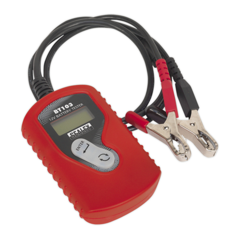
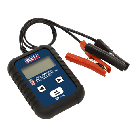
One of the most competitively priced, PC-based ‘scopes around and suitable
for professional applications. High sample rate, multiple memory function
and 4-channel display make this unit ideal for in-depth analysis of a variety
of automotive sensors and components and can be used with any
compatible lap-top or PC. The ‘scope also features a comprehensive
collection of standard automotive diagnostic procedures turning an otherwise
complex process into a click of a button. The system is loaded with
specimen wave-forms allowing the operator to compare actual results with
those expected. The 4-channel function allows multiple components to be
compared simultaneously. The TA4000 can be connected using a LAN cable
(supplied) to any PC running the appropriate software version. The scope is
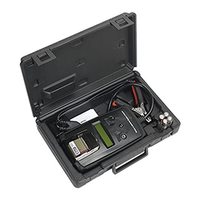
supplied with a wide selection of automotive type test leads, connectors and
probes. Supplied in carry case.
INPUT
Max. sample rate 200MS/s (Single Channel)
100MS/s (Dual Channel)
Channels 4 Channels
Bandwidth 60MHz (-3dB)
Vertical Resolution 8 bits/channel
Gain range
10mV ~ 5V/div @ x1 probe (10mv, 20mv, 50mv,
100mv, 200mv, 500mv, 1V, 2V, 5V/div 1,2,5 sequence)
100mV ~ 50V/div @ x 10 probe
1V ~ 500V/div @ x 100 probe
10V ~ 5KV/div @ x 100 probe
Range 8 divisions
Offset level +/-4 divisions
Coupling AC, DC, GND
Offset increments 0.02 div
Impedance 1M ohm
DC accuracy +/- 3%
Input protection 35Vpk (DC + peak AC < 10kHz, without external attenuation
Display Mode Y-T, X-Y
TIMEBASE
Timebase range 5ns/div ~ 1000s/div (1-2-5 sequence)
Acquisition mode Timebase range
Range Realtime sampling: 5ms/div ~ 200ms/div
Roll mode: 500ms/div ~ 1000s/div
Buffer Size 10K ~ 16M points (Single Channel)
TRIGGER
Type Edge trigger, Pulse Trigger
Mode Auto, normal and signal
Autoset Yes
Range 10 divisions
Trigger level +/-4 divisions
Settabillity 0.02 div increments
MATH
Measurements
Vpp, Vmax, Vmin, Vmean, Vrms, Vamp, Vtop, Vbase,
Vmid, positive overshoot, negative overshoot, cycle
mean, cycle RMS, period, frequency, positive pulse
width, negative pulse width, rise time (10%~90%), fall
time (10%~90%), positive duty cycle, negative duty cycle
Math Addition, Subtraction, Multiplication, FFT
FFT Rectangular, Hanning, Hamming, Blackman Window
PHYSICAL
Interface USB2.0 (USB1.1 compatible)
Power External power source required. (8.5v dc)
Dimensions 224 x 168 x 37mm
Original Language Version TA4000 Issue: 1 - 06/09/11
