Sealey V5402.V2 User manual

A IProfessional]
le!JLSlJJLb
l1
U
ITDDLS
~----------------
------~
Aula
Serv
ice
Line
INSTRUCTIONS FOR:
VACUUM TESTER AND
BRAKE BLEEDING KIT
MODEL
No.
V5402.V2
Thank you for purchas•ng a Sealey product Manufactured
to
a high standard this product will,
if
used according
to
these instruclions and properly maintained, give you years
of
trouble free performance.
l
b.._
IMPORTANT:
PLEASE
READ
TH
ESE
I
NSTRUCTIONS
CAREFULLY.
NOTE
THE
SAFE
OP
E
RATIONAL
REQUI
REMENTS,
WARNINGS
,
AND
ili
CAUTIONS
.
USE
THIS
PROD
UCT
CORRECTL
Y,
AND
WITH
CARE
FOR
THE
PURPOSE
FOR
WHICH
IT
IS
INTENDED
.
FAILURE
TO
DO
SO
MAY
CAUSE
DAMAGE
AND/OR
PERSONAL
INJURY
AND
WILL
INVALIDATE
THE
WARRANTY.
1.
SAFETY INSTRUCTIONS
./
Keep
this product in
good
wo
rking
order
and condition, take immediate action to repair
or
replace
damaged
parts.
./
Use
approved
parts
only.
Unapproved
parts
will
invalid
ate
the
warranty
.
./
Keep
child
ren
and
unauthoris
ed
persons
awa
y
from
the
work
area
.
./
Keep
worlk
area
cle
an
and
tidy
and
free
from unrelated
mate
r
ials
.
./
En
sure
t
he
worlk
area
has
adequate
lighting.
X
DO
NOT
use
t
he
kit
to
perform a task
for
which
it
is
not
des
igned.
X
DO
NOT
hold
pump
inle
t against the
skin
whilst
usi
ng
the
pump.
X
DO
NOT
allow
untrained persons
to
use
the kit.
X
DO
NOT
use
whilst u
nder
the influence
of
drugs, alcohol
or
intoxicating medication.
./
After
use
,
clean
equipment
a
nd
store in a cool, dry, ch
ildpr
oo
f area.
0
WARNING!
Brake fluid will
damage
paintwork.
Any
sp
illage should be flushed with
water
immediately.
0
WARNING!
Brake fluid is
flammab
le-
keep
away
from
sources
of
ignition, including
hot
surfaces e.g.
exhaust
manifold.
./
Dispos
e
of
w
aste
liquids in accordance with local-authority regulations.
0
WARNING!
DO
NOT
pollute
the
environment
by
allow
ing uncontrolled
discharge
of
fluids.
./
Always
read
and
comp
ly with
the
warnings
on
the
brake
fluid
contalller
.
./
Wear
eye
protection
and
keep
skin
contact
to
a
minunum
If
brake
fluid
eMers
eyes
rinse
with
plenty
of
water
and
seek
medical
advice.
If
swallowed
seek
medical
advice
immediately.
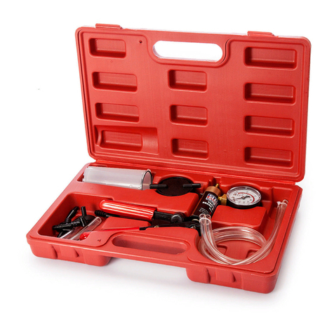
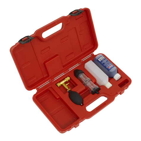
2. SPECIFICATION & CONTENTS
The
VS402.V2
vacuum
tester
and
brake
bleeding
kit is a multi-function diagnostic tool
used
to test a variety
of
essential engine a
nd
associated functions inclu
ding
fuel, ignition, transmission
and
emissions.
Set
also
includes reservoir,
hoses
and
adaptors
for bleeding brake and clutch
sys
t
ems
on cars.
commercia
ls
and
motor
cycles. Brass-bodied vacuum
pump
features large, easy-to-read vacuum gauge calibrated in
both
inches
and millim
et
res
of
mercury.
ITEM
PART
No
.
DESCRIPTION
I
TE
M PART
No
.
DESCRI
PT
ION
1 VS402.V2-01
VACUUM
P
UMP
WITH
GAUGE
6 VS402.V2-06 --·
··
--
HOSE
ADAP
T
OR
2A
VS402
.
V2-02A
RESERVOIR
LID
(FOR
OPERATION
) 7 VS402.V2-07
HOSE
ADAP
T
OR
'T-PIECE'
28
VS402.V2-02B
RESERVOIR
UD
(FOR
TRANSPORT)
8
VS402
.
V2-08
HOSE
ADAP
TOR
'STRAIGHT'
3
VS402.V2-03
RESERVOIR
JAR
9
VS402.V2-09
BRAKE
BLEED
NIPPLE
ADAPTOR
4
VS402.V2-04
560mm
VACUUM
HOSE
'
10
VS402
.V2-10 UNI
VERSAL
CUP
ADAPTOR
!:;
VS402.V2
-
05
80mm
VACUUM
H
OS
E
J
( C Jack SealeyLimited ) OriginalLanguage Verston ( VS402.V2 I
Issue
: 1 - 22/05/12 I

3. INTRODUCTION
The use
of
a vacuum gauge
is
often overlooked when determining mechanical condition and carrying out fault diagnosis
on
internal combustion engines.
Monitoring actual manifold vacuum
is
invaluable when troubleshooting engine faults. This can only be carried out
by
using a good qual
ity
vacuum gauge and this,
coupled with a hand-operated vacuum pump, also allows static testing
of
all types
of
vacuum operated systems. Set
out
on the following pages are applications
that the VS402.V2 vacuum tester kit can
be
used for, but
it
mustalways be remembered that these are examples only and reference to manufacturer's service
manuals should always be made for correct testing procedures and specifications.
In
addition to this,
it
is
always recommended that additional tests, ie.
compression tests, cylinder leakage tests, ignition timing checks etc. be carried out to confirm indications
of
vacuum gauge readings.
4. INLET MANIFOLD SYSTEMS
4.1.
Analysing
Engine
Mechanical
Conditi
on
via
Manifold
Vacuum
Readings
4.1.1. The readin
gs
shown below are only examples
of
what may be observed. It
is
important to remember that
it
is the action
of
the needle rather than the actual
reading that is more important. Varying engine types will run different manifold
vacuum pressures, depending on camshaft profile, valve overlap, timing etc. so
<;~n
exact vacuum reading cannot be specified. The main criteria is that
the
needle
reading
is
between 16 to 21inHg and steady.
4.1.2. Manifold vacuum is also affected by altitude and
it
will drop approximately 1inHg for
every 1000 feet above sea level so this rr.ust also be considered when assessing
manifold vacuum actual readings.
4.2.
Basic
Diagnostic
Tests
4.2.1. Carry out the following procedures:
Step 1. Run engine until normal operating temperature is reached.
Sw
itch engine off.
Step
2.
Connect the vacuum gauge to a port directly on the manifold {fig.1)
or
on the
carburettor/throttle body below the throttle butterfly.
Step 3. Start and run the engine at idle, observing the gauge reading.
4.2.2. Refer to the following table to indicate any problems and their possible causes.
(
<!:>
Ja
ck Sealey Limited
READING: 16·21 inHg
with
needle steady.
CAUSE: Normal.
READ
IN
: Read
in
gs
s
lig
h
tl
y l
ower
han
for
normal
engine
including
hen
thrott
le
is
s
udd
enly opened
then
released
.
AUSE:
Wom
piston
rings
. Carry
ut
compression
test
.
READING: When
the
throtlle
is
suddenly
opened
then
...-
the
needle
should
drop
to
below
5inHg
then
bounce
up
to
appro
ximately
2SinHg settling back
to
original
reading.
CA
·Normal.
READING: Reading
slightly
low
and
u
ctuating
slowly.
AUSE:
Over
lea.l
or
rich mixture.
heck
and
reset
in accordance with
manufacturers specifications.
Original Language Version
READING
:
~
extrwnoly
low
steady.
USE: l.eaD>g
inl*e-
system,
Faulty
manifotdgasl<et,
cal'buretto.-
base
gasket.
split
vacuum hose.
EGR
va
l
ve
seized.
READING: Regular
fluctua
t
ion
between normal
and
low
re3dings.
CAUSE: Blown head gasketbetween
o adjacentcylinders. Carry
out
yl
inder
leakage
test
EADING: Normal
when
firs
t
starte
ut
drops
rapid
ly
when
revs
he
ld
at
OOOrpm.
AUSE: Restriction
in
exhaust
VS402.V2 I Issue: 1 - 22/051
12
)

4.3.
Ignitio
n
System
Vacuum
Advance
4.3.1.
On
standard
poi
nts systems and
some
electronic ignition s
ystems
there
are
two
types
of
advanc
e
methods
used, both
of
wh
ich
must
function
correctly
to
obtain
maximum
performa
nce
and fuel
economy
.
4.3.2.
The
first
method
Is
Mechanica
l
or
Centrifugal,
which
operates
by
the
us
e
of
weights located in t
he
bas
e
of
the
dist
ributor.
Th
e weights
mov
e
ou
tw
ards
advancing ignition timing as engine
RPM
incr
eases. T
his
is
tested
by
firstly removing
the
vacu
um
advance line to
disab
le the
syste
m,
then with a timing
light
connected, run the
engine
RPM
up
chec
king that the !Jrr ng
adv
aoces
1n
accordance
with
the
manu
fact
ur
er's
specif
ication.
4.3.3.
The
second method is
Vacuum
Advanc
e, which
senses
engine
load
via manifold vacuum. A
vacuum
diaphragm is
moun
te
d
onto
the
distn
l)lllor
an
d
connected
to
a rotating internal
base
plate
which
advance
s
or
retards timing
as
required
to
suit
varying
eng
ine loads.
To
t
es
t this
system
for
correct
ope
ra
tio
n,
again
with
the
ti
m
ing
light
conne
cted. ra
ise
the
engine
RPM
and
check
timing
advanc
e against
ma
nufa
cture
r specifications. In the
event
t
hat
the
vacuum
advance
is
not
oper
2ting, re
mov
e the vacu
um
line
fr
om
t
he
distributor
advanc
e mechanism.
Con
nect
the
VS4
02.V2
(fig.2)
and
create a 5-10inHg
vacuum, monitoring the timing at
the
same
t
im
e.
If
a timing
advance
is
noted this confirms that
the
vacuum
diap
hragm and
mec
ha
nical
l
i
nk~
are in
ord
er
and
that
the fault is a
vacuum
supp
ly.
To con
fir
m this,
connect
the VS402.
•12
tc
the
vacu
um
supply
line
an
d
check
the g
auge
reading.
No
vacuum
should
be
noted
at
idle
but
when the engine
RPM
is increased a
vacuum
increase should
be
observed.
If
this do
e::;
not
o
ccur
, 1race
the
va~uPm
i<n
e back <:ht. king
for
restrictions
and
breaks.
--
-...
(fig.3
lj
/
5.\ FUEL SYSTEMS
5.1.
Testing
Mechanical
Fuel
Pumps
5.1.1.
The
VS402.V2 vacuum tester can
be
used
to
evaluate
the
condition
of
a mechanical fuel
pump
by
testing the v
acuu
m th
at
it is
able
to create. Locate and
remove
the
suction line
fro
m the pump. Connect
the
VS402.V2
v
ac
uum
tester
to
the
suct
ion
port
of
the pump,
start
and run t
he
engine
at
idle.
The
vacuum
reading
that
should
be
observed
wH
I
vary
slightly
on
different
makes
and
models
but
as
a general rule
app
roximately
15in
Hg
of
v
acuum
should
be
created.
This should
also
be held
for
approximately 1 minute after engine shut down.
If
this
vacuum
reading is
not
achi
eved
or
the v
acuu
m
drops
off
immediately
with
the engine
shut
down, the fuel pul'np requires
either
overhaul
or
rep
lac
ement.
5.2.
Carburettors
'~
~
5.2.1.
There
are
many
different
types
c;>f
vacuum
control
systems
used on carburettors. Using
the
VS402.V2 vacuum
tester
kit allows
quick
and
accura
te testing of
these systems. Listed
below
are
just
two
examples
of
tests
that
can
be
carried
out:
5.2.2. Testing a
Choke
Break Diaphragm.
With
the engine at-normal operating
temperature
but
not
running,
disconnect
the
vacuum
line
to
the
diaphragm
module.
Connect
the
VS402
.V
2
vacuum
tester
(fig.3)
and
apply
approximately
15inHg
of
vacuum
and
wait
for
30
seconds.
No
dr
op
in
gauge
reading should
be
observed.
With the
vacuum
still applied
ensure
that
the
choke
butterfly
is
pulled
to
the fully
open
position.
5.2.3. Testing
Vacuum
Operated Carburettor
Secondary
B
arre
t Wrth
the
engine
at normal operating temperature
but
not
running,
remov
e t
he
vacuum line from t
he
seco
nd
ary
diaphragm
module.
Connect
the
VS402.V2
vacuum
tester
{fig.4
),
hold the throttle
and
secondary
air
va
lv
e flaps open.
Ope
r
ate
the hand pu
mp
wh
ilst
observing free and
easy
opening
of
the
second
ary
throttle butterfly.
5.3.
Testing
Fuel
Injection
Pressure
Regulator
5.3.1. Multi-po
int
fuel injection rail pressure
must
vary
to
suit changing engi
ne
load
s
and
fu
el
delivery
re
quirements
.
This
is
done
usi
ng
a v
acuum
oper
ated
regulator
which
is connected
to
the engi
ne
manifold vacuum to sense the varyi
ng
loads.
5.3.2. To test
the
fuel rail pressure, a
gauge
is attached
to
the
rail,
then
engine
loads
must
be created
to
vary engine manifold vacuum. Si
mply
r
emove
and
block
off
the
vacuum
supply
line
to
the
pressure
regulator,
connect
and
operate
the
VS402.V2
vacuum
pu
mp
(fig.5) to simulate va
cuum
pressures in
accordance
with
the manufacturer's specifications and
note
variation in fuel pressure reading.
5.4.
Testing
Emission
Cont
rol
Exhau
st
Gas
Recirculation
Valves
(EGR)
5.4.1.
Start
engine
and
run
at
idle until normal operati
ng
temperature is reached.
Remove
the
vacuum
line
from
t
he
EGR
va
l
ve
a
nd
a
tt
ac
h the
VS402.V
2 vacuum
tester
kit (fig.6). Operate the hand
pump
to
apply
approx
imately
15inHg
of
vacuum.
If
the
EGR
Valve is
wor
king correctly t
he
e
ngin
e idle will
become
rough.
If
the idle remains
unchang
ed the
valve
is
possibly
seized in
the
closed position.
If
the
vacuum
is
no
t held, the
diaphragm
in the valve
has
failed.
( ©
Jack
Sealey
Limite
d OriginalLanguage Version I V
S4
02.V2 I
Issue:
1 • 22/05
/1
2 )

6. ADDITIONAL VACUUM SYSTEMS
6.1. Testing One-Way Valves
6.1.1. Many vacuum operated circuits use in-line one-way valves to apply vacuum in
one
direction only.
6.1.2.
To
test the function
of
the valve remove it from the circuit. Attach the VS402.V2 vacuum tester (fig.7) and operate pump to apply vacuum. In one direction
the valve shou
ld
hold vacuum and in the opposite d
ir
ection it should not.
6.2.
Testing
Electrically
Operated
Vacuum
Solenoids
6.2.1. Electrically operated vacuum solenoids are commonly used in control c
ir
cuits
for
airconditioning/ventilation systems, emission control syste
ms
, idle step
up
systems etc. and testing the function
of
these when using
the
VS402.V2
is
extremely simple.
6.2.2. Locate the solenoid to be tested and remove the line that goes to the component being tested. Connect the VS402.V2 to the solenoid port (fig.8) and start
the engine. With the system turned offthere should·be a zero gauge reading. Nowturn the system to the 'on' position and a gauge reading equal
to
the
manifold vacuum should be observed,
if
no
reading exists remove the vacuum supply line and test
for
manifold vacuum
at
this point. If the vacuum does
exist this indicates that the solenoid is faulty
or
it
is
no
t receiving a 'switch on' voltage (use a multimeter to test this). If no vacuum exists trace the supply
line backto the vacuum source checking
for
kinks and breaks.
6.3.
Testing
Thermal
Vacuum
Sw
itc
hes
6.3.1. There are
many
vacuum controlled circuits that must only operate when the en
gi
ne reaches nonnal operating temperature. This is done usi
ng
thennal
switches that remain in an
'off
position until a given temperature
is
reached.
6.3.2. To test this type of switch, remove the vacuum supply line co
mi
ng
from the manifold to t
he
switch and test for manifold vacuu
m.
If
this vacuum is correct refit
the supply line to the thermal switch and remove the opposing line from the switch. Attach the VS402.V2 vacuum tester to the
po
rt (fig.9) and start the
engine. With a cold engine
no
reading shou
ld
be noted. When the engine reaches nonnal operating temperature a manifo
ld
vac
uum reading should be
noted.
6.4.
Testing
Vacuum
Operated
Heater
Taps
6.4.1. Climate control ventilation systems are becoming very common on newervehicles and most of
the
systems use vacuum operated taps to control the heating
modes.
On
the majority
of
makes and models, the system uses vacuum to tum the heat
er
tap 'on'.
6.4.2. To test these remove the supply line from the tap vacuum m
od
ule and connect the VS402.V2 vacuum tester (fig.10). With the engine
at
nonnal operating
temperature locate and feel
the
heater return hose. With the heatertap in the '
otr
position, this hose should be cold. Now operate the vacu
um
pump to open
the tap.The gauge read
in
g must hold. If
the
tap is in working order. the retum hose will begin to heat.
If
the
ho
se does not begin to heat, this indicates that
the tap is faulty.
6.5.
Testing
Vacuum
Operated
Remote
Central
Locking
Systems
6.5.1. Some makes and models use vacuum operated bellows mounted in each
door
to centrally lock and
un
lock the
veh
icles doors. These systems use either
manifold vacuum stored in a reservoir
for
use when the engine
is
not
running
or
an electrically driven vacuum pump which operates
wh
en the doors are
locked
or
unlocked.
6.5.2. In either system, the VS402.V2 vacuum tester
is
ideal for testing each individu
al
door bellows. To do this. removA the door trims as required. Remove the
vacuum supply lines from the bellows and attach the VS402.V2 vacuum tester (fig.11 ) and operate to apply vacuum to the bellows. Wait
for
30 seconds,
no
drop on the gauge should be noted.
If
the bellows are found to be
in
order attach the vacuum supply line to the VS402.V2 vacuum tester and operate
system to test for vacuum supply.
If
the vacuum supply does not exist
or
is low trace back down the lines to the vacuum supply looking for kinks, restrictions
or
cracked lines. Repair as required and retest.
6.6.
Testing
Automati
c
Transmission
Vacuum
Operated
Modulator
Valves
6.6.1. Automatic transmissions are nonnally equipped with a vacuum operated modulator valve in order for the automatic transmission to detect engine loads and
adj
ust
shift points to suit. ·
6.6.2. The VS402.V2 vacu
um
tester can be used to test both that the modulation valve diaphragm
is
serviceable and
al
so to simulate varying engine loads so
modulator pressure readings can be recorded.
To
test the modulator valve diaphragm remove
the
vacuum supply line from the valve and attach the
VS402.V2 vacuum tester. Operate t
he
vac
uum pu
mp
until approximately 15in
Hg
is achieved
and
monitor
the
gauge
reading
for
approximately 30 seconds.
No
vacuum drop should be noted.
6.6.3.
To
ctle
ck modulator pressure readings attach a pressure gauge to the appropriate port
on
the transmission. RerllOYe the
vaaMTI
supply
line from the
modu
la
tor and attach the VS402.
V2
vacuum tester (fig.
12
). Start and run the engi
ne
and apply
vac
uum pressures.
Monitor
readings and confinn that
these
are in conformance with manufacturer specifications.
(
C>
J
ac
k Sealey Umited
l
To
Manifold
) Vawum
Original Language Version ( VS402.V2 I Issue: 1 •
2210
51
12
)
7. BRAKING SYSTEMS
7.1. Testing Brake Servo Diaphragm
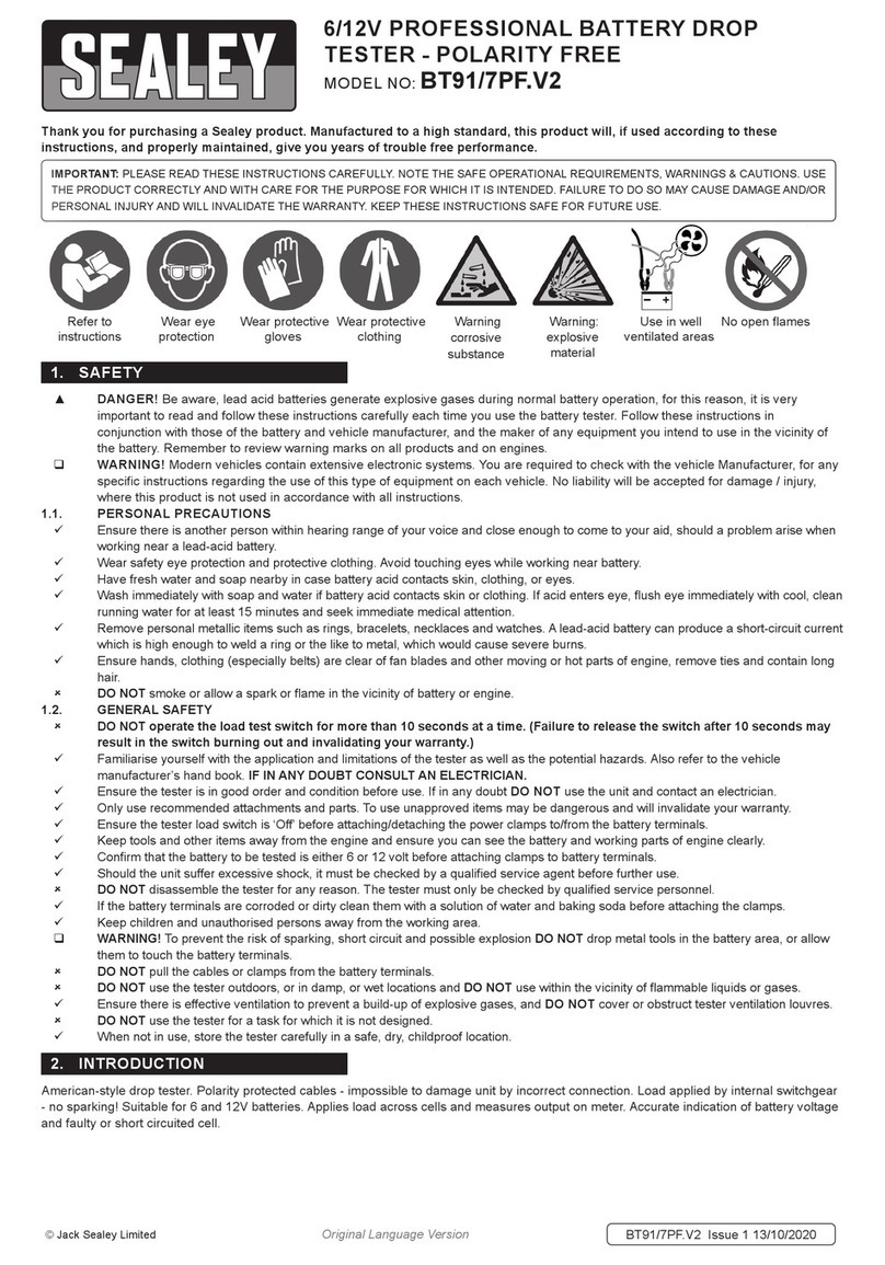
7.1.1. Remove vacuum supply line from brake servo fitting. Attach VS402.V2 vacuum tester to vacuum supply port
on
servo (fig.13). Operate pump to create
approximately 15inHg
of
vacuum and wait for
30
seconds. No vacuum drop should
be
observed on the gauge reading. If the vacuum drops this indicates
that the brake servo diaphragm
is
faul
ty.
In
th
is
case the servo should
be
removed for overhaul by
an
authorised repa
ir
er
or
replaced.
7.2. Brake
Bleeding
·Assembly
of
Brake Bl
eeder
Kit
7.2.1. Ensure that the vacuum pump
is
connected to the brake bleeder reservoir in accordance with the assembly diagram (fig
.1
4). Failure to do so wi
ll
result in
brake fluid being drawn into the vacuum pump.
7.3. Brake
Bleeding
Procedure.
LJ
WARNING/
Familiarise
yourself
with
the
hazards
of
brake
fluid
-
read
manufacturer's
instructions
on
the container.
Do
not
touch
the
vehicle's
brake
pedal
whilst
bleeding
the brakes.
7.3.1. Refer to the specific vehicle manufacturer's instructions for brake bleeding and wheel sequence procedure before proceeding. If no specific instructions
from the vehicle manufacturer exist, follow the instructions detailed below.
7.3.2. Remove the cap
of
the vehicle's master brake flu
id
reservoir.
If
the
fl
uid level is not at maximum, top it up.
7.3.3. Attach the appropriate size bleeding attachment
to
the bleed nipple
on
the brake calliper of the first wheel, normally nearest to master brake fluid reservoir.
7.3.4. Operate vacuum pump unt
il
approximately 21inHg vacuum is created.
7.3.5. Apply copper grease to the brake bleeding nipples before and after the brake bleeding procedure to reduce the possibility
of
se
ized
or
broken ni
pp
les
when the brakes are next bled.
7.3.6. Open the bleed nipple about a quarter
of
a tum. Allow brake fluid to be drawn until no air bubbles are visible
in
the brake fluid in the clear hose.
7.3.7.
lighten
the bleed nipple.
7.3.8. Remove the attachment from the brake nipple.
7.3.9. Repeat the process as necessary.
NOTE! Check the master brake fluid reservoir regularly to ensure that the level does not drop too far, and top up as necessary.
NOTE! Empty bleeder container regularly
and
DO NOT allow container to overfill as brake fluid will be drawn into vacuum pump.
LJ
WARNING! When
brak
e bleeding
and/or
fluid
changing is complete,
test
the
action
of
the
brake pedal
to
ensure
th
at
the
brakes are
working
before
attempting
to
drive
the
vehicle
on
the
road and
test
the
vehicle
for
satisfactory
perfo
rmanc
e
of
the
brakin
g system.
7.4.
Cl
ut
ch
Bleeding Procedure.
7.4.1. Refer
to
the relevant vehicle manufacturer's instructions for clutch bleeding procedure.
If
no specific instructions from the vehicle manufacturer exist, fo
ll
ow
the same basic procedure as the brake bleeding instructions above.
( © Jack SealeyLimited J Original Language Version ( VS402.V2 I Issue: 1 - 22/05/12 )

t
0
NOTE:
It
is
ou
r p
ol
icy
to continually improve products
an
d
as
such
we
reseNe
the right to alterdata, specifications
and
component
pa
rts without
prior
notice.
IMPORTANT:
No
liability is accept
ed
for incorrect use
of
this product.
WARRANTY: Guarantee·is 12 months from purchase date, proof
of
which will
be
required for any claim.
INFORMATION: For a copy
of
our latest catalogue and promotions call
us
on 01284 757525 and leave your full name and address, including postcode.
~
IPrafe
ssianatJ
Sole
UK
Distributor
,
S
ea
l
~y
Group,
~
01284 757500 r.it\
l
QUl..1~l..1L1
uI
TDDLS
Kempson
Way
, Suffolk
BU
Siness Park, u.b www.sealey
.c
o.uk
~----::
:'=
-=::=-=
=--==---.J.
•
Bury
St.
Edmu
nd
s,
Suffolk,
~
01284 703534
1¥11
sales@seal
eyco.uk
Auta
Serv•ce
L•ne
I
P327AR
~
~,.
_
( @Jack Seal
ey
Limited
Original
Language
Version I VS402.V2 Issue· 1 - ??/OS/1? 1
Table of contents
Other Sealey Test Equipment manuals

Sealey
Sealey VS0275 User manual

Sealey
Sealey VS0014 User manual

Sealey
Sealey AUTO SERVICE LINE TA125 User manual

Sealey
Sealey VS270 User manual

Sealey
Sealey VSE2020.V2 User manual

Sealey
Sealey MC105 User manual

Sealey
Sealey AUTO SERVICE VSE206 User manual

Sealey
Sealey TST22 User manual

Sealey
Sealey BT2013.V5 User manual

Sealey
Sealey CT955 V3 User manual

Sealey
Sealey BT101 User manual

Sealey
Sealey PPVT User manual

Sealey
Sealey BT91/11 User manual

Sealey
Sealey VS027.V2 User manual

Sealey
Sealey AUTO SERVICE BT91/7C User manual

Sealey
Sealey Auto Service Line VS2030 User manual

Sealey
Sealey BT91/7P User manual

Sealey
Sealey VSE952 User manual

Sealey
Sealey BT91/7PF User manual

Sealey
Sealey CT955.V2 User manual